DE102011112821B4 - Electric motor, in particular radiator fan motor - Google Patents
Electric motor, in particular radiator fan motor Download PDFInfo
- Publication number
- DE102011112821B4 DE102011112821B4 DE102011112821A DE102011112821A DE102011112821B4 DE 102011112821 B4 DE102011112821 B4 DE 102011112821B4 DE 102011112821 A DE102011112821 A DE 102011112821A DE 102011112821 A DE102011112821 A DE 102011112821A DE 102011112821 B4 DE102011112821 B4 DE 102011112821B4
- Authority
- DE
- Germany
- Prior art keywords
- insulation displacement
- busbars
- electric motor
- contacts
- insulation
- Prior art date
- Legal status (The legal status is an assumption and is not a legal conclusion. Google has not performed a legal analysis and makes no representation as to the accuracy of the status listed.)
- Expired - Fee Related
Links
- 238000009413 insulation Methods 0.000 claims abstract description 68
- 238000006073 displacement reaction Methods 0.000 claims abstract description 61
- 238000004804 winding Methods 0.000 claims abstract description 32
- 239000003990 capacitor Substances 0.000 claims abstract description 26
- 230000001629 suppression Effects 0.000 claims description 14
- 238000005520 cutting process Methods 0.000 claims description 9
- 238000003860 storage Methods 0.000 claims description 7
- 239000003973 paint Substances 0.000 claims description 6
- 238000003780 insertion Methods 0.000 claims description 4
- 230000037431 insertion Effects 0.000 claims description 4
- 238000007789 sealing Methods 0.000 description 9
- 238000002425 crystallisation Methods 0.000 description 4
- 230000008025 crystallization Effects 0.000 description 4
- 238000005096 rolling process Methods 0.000 description 4
- 229910000679 solder Inorganic materials 0.000 description 4
- 210000002414 leg Anatomy 0.000 description 3
- 230000013011 mating Effects 0.000 description 3
- 239000007787 solid Substances 0.000 description 3
- RYGMFSIKBFXOCR-UHFFFAOYSA-N Copper Chemical group [Cu] RYGMFSIKBFXOCR-UHFFFAOYSA-N 0.000 description 2
- 238000001816 cooling Methods 0.000 description 2
- 238000011161 development Methods 0.000 description 2
- 230000018109 developmental process Effects 0.000 description 2
- 238000005304 joining Methods 0.000 description 2
- 238000005299 abrasion Methods 0.000 description 1
- XAGFODPZIPBFFR-UHFFFAOYSA-N aluminium Chemical compound [Al] XAGFODPZIPBFFR-UHFFFAOYSA-N 0.000 description 1
- 229910052782 aluminium Inorganic materials 0.000 description 1
- 230000015572 biosynthetic process Effects 0.000 description 1
- 229910052802 copper Inorganic materials 0.000 description 1
- 239000010949 copper Substances 0.000 description 1
- 230000001419 dependent effect Effects 0.000 description 1
- 230000000694 effects Effects 0.000 description 1
- 238000004146 energy storage Methods 0.000 description 1
- 238000005516 engineering process Methods 0.000 description 1
- 238000002347 injection Methods 0.000 description 1
- 239000007924 injection Substances 0.000 description 1
- 238000002955 isolation Methods 0.000 description 1
- 238000003475 lamination Methods 0.000 description 1
- 238000004321 preservation Methods 0.000 description 1
- 238000003825 pressing Methods 0.000 description 1
- 239000004065 semiconductor Substances 0.000 description 1
- 210000000689 upper leg Anatomy 0.000 description 1
Images


Classifications
-
- H—ELECTRICITY
- H02—GENERATION; CONVERSION OR DISTRIBUTION OF ELECTRIC POWER
- H02K—DYNAMO-ELECTRIC MACHINES
- H02K11/00—Structural association of dynamo-electric machines with electric components or with devices for shielding, monitoring or protection
- H02K11/01—Structural association of dynamo-electric machines with electric components or with devices for shielding, monitoring or protection for shielding from electromagnetic fields, i.e. structural association with shields
- H02K11/014—Shields associated with stationary parts, e.g. stator cores
- H02K11/0141—Shields associated with casings, enclosures or brackets
-
- H—ELECTRICITY
- H01—ELECTRIC ELEMENTS
- H01R—ELECTRICALLY-CONDUCTIVE CONNECTIONS; STRUCTURAL ASSOCIATIONS OF A PLURALITY OF MUTUALLY-INSULATED ELECTRICAL CONNECTING ELEMENTS; COUPLING DEVICES; CURRENT COLLECTORS
- H01R12/00—Structural associations of a plurality of mutually-insulated electrical connecting elements, specially adapted for printed circuits, e.g. printed circuit boards [PCB], flat or ribbon cables, or like generally planar structures, e.g. terminal strips, terminal blocks; Coupling devices specially adapted for printed circuits, flat or ribbon cables, or like generally planar structures; Terminals specially adapted for contact with, or insertion into, printed circuits, flat or ribbon cables, or like generally planar structures
- H01R12/50—Fixed connections
- H01R12/59—Fixed connections for flexible printed circuits, flat or ribbon cables or like structures
- H01R12/63—Fixed connections for flexible printed circuits, flat or ribbon cables or like structures connecting to another shape cable
-
- H—ELECTRICITY
- H01—ELECTRIC ELEMENTS
- H01R—ELECTRICALLY-CONDUCTIVE CONNECTIONS; STRUCTURAL ASSOCIATIONS OF A PLURALITY OF MUTUALLY-INSULATED ELECTRICAL CONNECTING ELEMENTS; COUPLING DEVICES; CURRENT COLLECTORS
- H01R12/00—Structural associations of a plurality of mutually-insulated electrical connecting elements, specially adapted for printed circuits, e.g. printed circuit boards [PCB], flat or ribbon cables, or like generally planar structures, e.g. terminal strips, terminal blocks; Coupling devices specially adapted for printed circuits, flat or ribbon cables, or like generally planar structures; Terminals specially adapted for contact with, or insertion into, printed circuits, flat or ribbon cables, or like generally planar structures
- H01R12/50—Fixed connections
- H01R12/59—Fixed connections for flexible printed circuits, flat or ribbon cables or like structures
- H01R12/65—Fixed connections for flexible printed circuits, flat or ribbon cables or like structures characterised by the terminal
- H01R12/67—Fixed connections for flexible printed circuits, flat or ribbon cables or like structures characterised by the terminal insulation penetrating terminals
- H01R12/675—Fixed connections for flexible printed circuits, flat or ribbon cables or like structures characterised by the terminal insulation penetrating terminals with contacts having at least a slotted plate for penetration of cable insulation, e.g. insulation displacement contacts for round conductor flat cables
-
- H—ELECTRICITY
- H01—ELECTRIC ELEMENTS
- H01R—ELECTRICALLY-CONDUCTIVE CONNECTIONS; STRUCTURAL ASSOCIATIONS OF A PLURALITY OF MUTUALLY-INSULATED ELECTRICAL CONNECTING ELEMENTS; COUPLING DEVICES; CURRENT COLLECTORS
- H01R4/00—Electrically-conductive connections between two or more conductive members in direct contact, i.e. touching one another; Means for effecting or maintaining such contact; Electrically-conductive connections having two or more spaced connecting locations for conductors and using contact members penetrating insulation
- H01R4/24—Connections using contact members penetrating or cutting insulation or cable strands
- H01R4/2416—Connections using contact members penetrating or cutting insulation or cable strands the contact members having insulation-cutting edges, e.g. of tuning fork type
- H01R4/242—Connections using contact members penetrating or cutting insulation or cable strands the contact members having insulation-cutting edges, e.g. of tuning fork type the contact members being plates having a single slot
- H01R4/2425—Flat plates, e.g. multi-layered flat plates
-
- H—ELECTRICITY
- H02—GENERATION; CONVERSION OR DISTRIBUTION OF ELECTRIC POWER
- H02K—DYNAMO-ELECTRIC MACHINES
- H02K11/00—Structural association of dynamo-electric machines with electric components or with devices for shielding, monitoring or protection
-
- H—ELECTRICITY
- H02—GENERATION; CONVERSION OR DISTRIBUTION OF ELECTRIC POWER
- H02K—DYNAMO-ELECTRIC MACHINES
- H02K11/00—Structural association of dynamo-electric machines with electric components or with devices for shielding, monitoring or protection
- H02K11/30—Structural association with control circuits or drive circuits
- H02K11/33—Drive circuits, e.g. power electronics
-
- H—ELECTRICITY
- H02—GENERATION; CONVERSION OR DISTRIBUTION OF ELECTRIC POWER
- H02K—DYNAMO-ELECTRIC MACHINES
- H02K3/00—Details of windings
- H02K3/46—Fastening of windings on the stator or rotor structure
- H02K3/50—Fastening of winding heads, equalising connectors, or connections thereto
-
- H—ELECTRICITY
- H02—GENERATION; CONVERSION OR DISTRIBUTION OF ELECTRIC POWER
- H02K—DYNAMO-ELECTRIC MACHINES
- H02K2211/00—Specific aspects not provided for in the other groups of this subclass relating to measuring or protective devices or electric components
- H02K2211/03—Machines characterised by circuit boards, e.g. pcb
-
- H—ELECTRICITY
- H02—GENERATION; CONVERSION OR DISTRIBUTION OF ELECTRIC POWER
- H02K—DYNAMO-ELECTRIC MACHINES
- H02K5/00—Casings; Enclosures; Supports
- H02K5/04—Casings or enclosures characterised by the shape, form or construction thereof
- H02K5/22—Auxiliary parts of casings not covered by groups H02K5/06-H02K5/20, e.g. shaped to form connection boxes or terminal boxes
- H02K5/225—Terminal boxes or connection arrangements
Landscapes
- Engineering & Computer Science (AREA)
- Power Engineering (AREA)
- Microelectronics & Electronic Packaging (AREA)
- Physics & Mathematics (AREA)
- Electromagnetism (AREA)
- Insulation, Fastening Of Motor, Generator Windings (AREA)
- Motor Or Generator Frames (AREA)
- Motor Or Generator Cooling System (AREA)
Abstract
Elektromotor (5) mit einem eine Drehfeldwicklung (7) tragenden Stator (6) und mit einem gegenüber dem Stator (6) drehbar gelagerten, permanenterregten Rotor (8) sowie mit einer Umrichterelektronik (15) mit einer Leiterplatte (30), auf der eine Anzahl von als Klemm- oder Schneidklemmkontakte ausgebildete Kontaktelementen (31, 41) für isolationsfreie oder lackisolierte Anschlusskontakte (33, 35) mindestens eines Bauelementes (32, 34) der Umrichterelektronik (15) und/oder für lackisolierte Wicklungsenden (26) der Drehfeldwicklung (7) montiert sind, wobei ein Stromschienenpaar (36) mit einer Anzahl von Klemmkontakten (41) vorgesehen ist, die der Anzahl von isolationsfreien Anschlusskontakten (35) mindestens eines Ladekondensators (34) entsprechen, dadurch gekennzeichnet, – dass die Leiterplatte (30) eine Anzahl von Steckschlitzen (38) und/oder Stecklöchern (39) aufweist, in denen das Stromschienenpaar (36) mit korrespondierenden Einpressstiften (40) einsitzt, und – dass in die Leiterplatte (30) zwischen den Steckschlitzen (38) bzw. Stecklöchern (39), die den beiden Stromschienen (36a, 36b) des Stromschienenpaares (36) zugeordnet sind, eine Anzahl von zu den Stromschienen (36a, 36b) parallel verlaufende Ausnehmungen (37) eingebracht sind.Electric motor (5) with a stator (6) carrying a rotating field winding (7) and with a permanently excited rotor (8) mounted rotatably relative to the stator (6) and with a converter electronics (15) having a printed circuit board (30) on which Number of contact elements (31, 41) designed as clamping or insulation displacement contacts for insulation-free or enamel-insulated connection contacts (33, 35) of at least one component (32, 34) of the converter electronics (15) and / or for lacquer-insulated winding ends (26) of the rotating field winding (7 ), wherein a pair of busbars (36) with a number of terminal contacts (41) is provided, which correspond to the number of insulation - free connection contacts (35) of at least one charging capacitor (34), characterized in that - the circuit board (30) has a number of plug-in slots (38) and / or plug holes (39), in which the pair of busbars (36) with corresponding Einpressstiften (40) is seated, and - that in the Leit erplatte (30) between the plug-in slots (38) and plug holes (39) which are associated with the two busbars (36a, 36b) of the busbar pair (36), a number of parallel to the busbars (36a, 36b) recesses (37 ) are introduced.
Description
Die Erfindung betrifft einen Elektromotor gemäß dem Oberbegriff des Anspruchs 1. Ein derartiger Elektromotor ist beispielsweise aus der
Ein derartiger Elektromotor umfasst üblicherweise einen gegenüber einem feststehenden Stator oder Ständer drehbar gelagerten Rotor bzw. Läufer. Bei einem bürstenlosen Elektromotor ist der Stator häufig mit einer Drehfeldwicklung bestückt, mit der durch deren Beaufschlagung mit einem Wechselstrom ein magnetisches Drehfeld erzeugt wird. Der innerhalb des im Wesentlichen hohlzylindrischen Stators angeordnete Rotor ist in der Regel mit Permanentmagneten bestückt, die ein mit dem Drehfeld des Stators wechselwirkendes Rotormagnetfeld erzeugen.Such an electric motor usually comprises a relative to a fixed stator or stator rotatably mounted rotor or rotor. In a brushless electric motor, the stator is often equipped with a rotating field winding, which is generated by the application of an alternating current, a magnetic rotating field. The arranged within the substantially hollow cylindrical stator rotor is usually equipped with permanent magnets which generate a rotor magnetic field interacting with the rotating field of the stator.
Bei einem bürstenlosen Elektromotor wird der zur Speisung der Stator- bzw. Drehfeldwicklung vorgesehene Wechselstrom üblicherweise durch einen Umrichter (Wechselrichter) erzeugt. Der diesbezüglich übliche Wechselrichter richtet eine Gleichspannung, insbesondere die Bordnetzspannung des Kraftfahrzeugs, in eine Wechselspannung zur Speisung der Drehfeldwicklung um. Bei kleineren Elektromotoren ist dieser Umrichter zusammen mit einer zugeordneten Steuerelektronik häufig in ein Elektronikfach aufgenommen, das in das Motorgehäuse integriert ist.In a brushless electric motor, the alternating current provided for feeding the stator or rotary field winding is usually generated by a converter (inverter). In this regard, the usual inverter directs a DC voltage, in particular the vehicle electrical system voltage of the motor vehicle, in an AC voltage for feeding the rotating field winding. For smaller electric motors, this inverter is often included together with an associated control electronics in an electronics compartment, which is integrated into the motor housing.
Die Steuerelektronik umfasst üblicherweise eine Entstördrossel (EMV-Schutz), ggf. einen Entstörkondensator sowie einen gleichstromseitigen Energiespeicher in Form eines oder mehrerer Speicher- oder Ladekondensatoren (Elektrolytkondensatoren). Die Entstördrossel und der oder jeder Ladekondensator sowie weitere, insbesondere aktive Bauelemente in Form von Leistungshalbleitern, die in einer Brückenschaltung verschaltet und mit der Drehfeldwicklung verbunden sind, sind in der Regel auf einer Leiterplatte montiert und dort untereinander schaltungstechnisch verbunden. Die Kontaktierung der Bauelemente bzw. der Drehfeldwicklungsenden erfolgt mittels Lötverbindungen oder gemäß der eingangs genannten
Der Erfindung liegt daher die Aufgabe zugrunde, einen Elektromotor der genannten Art anzugeben, dessen Elektronik, insbesondere deren Bauelemente oder Anschlusskomponenten, mit möglichst geringem Aufwand zuverlässig kontaktiert werden kann bzw. können.The invention is therefore based on the object of specifying an electric motor of the type mentioned, the electronics, in particular their components or connection components, can be reliably contacted with the least possible effort or can.
Diese Aufgabe wird erfindungsgemäß gelöst durch die Merkmale des Anspruchs 1. Vorteilhafte Varianten, Ausgestaltungen und Weiterbildungen sind Gegenstand der Unteransprüche.This object is achieved by the features of claim 1. Advantageous variants, refinements and developments are the subject of the dependent claims.
Hierzu umfasst der Elektromotor, der insbesondere als Kühlerlüftermotor eines Kraftfahrzeugs eingesetzt ist, einen mit einer Drehfeldwicklung bewickelten Stator und einen gegenüber diesem drehbar gelagerten Rotor sowie eine Umrichterelektronik zum Umrichten einer Gleichspannung, insbesondere der Bordnetzspannung des Kraftfahrzeugs, in eine Wechselspannung zur Speisung der Drehfeldwicklung. Diese ist insbesondere in Form mehrerer Spulen oder Spulenwicklungen hergestellt, die vorzugsweise miteinander zu einer Dreiecksschaltung verbunden bzw. verschaltet sind. Der Rotor ist vorzugsweise permanenterregt und hierzu mit Magneten bestückt.For this purpose, the electric motor, which is used in particular as a cooling fan motor of a motor vehicle, a wound with a rotating field winding stator and a rotatably mounted relative to this rotor and Umrichterelektronik for converting a DC voltage, in particular the vehicle electrical system voltage of the motor vehicle, in an AC voltage for feeding the rotating field winding. This is produced in particular in the form of a plurality of coils or coil windings, which are preferably connected or interconnected to form a triangular circuit. The rotor is preferably permanently excited and equipped with magnets for this purpose.
Auf eine Leiterplatte der Umrichterelektronik sind eine Anzahl von Kontaktelementen für isolationsfreie Anschlusskontakte mindestens eines Bauelementes der Umrichterelektronik, insbesondere des oder jedes Ladekondensators, sowie für lackisolierte Kontaktelementen bzw. Anschlusskontakte, insbesondere für Wicklungsenden der Drehfeldwicklung und/oder für Kontakt- oder Spulenenden der Entstördrossel, montiert. Die Kontaktelemente sind als Klemmkontakte, insbesondere für den oder jeden Ladekondensatoren, oder als Schneidklemmkontakte für die lackisolierte Wicklungs- bzw. Kontaktenden ausgebildet.On a circuit board of the converter electronics, a number of contact elements for insulation-free terminal contacts of at least one component of the converter electronics, in particular the or each charging capacitor, as well as for paint-insulated contact elements or connection contacts, in particular for winding ends of the rotating field winding and / or for contact or coil ends of the suppression choke mounted , The contact elements are designed as terminal contacts, in particular for the or each charging capacitors, or as insulation displacement contacts for the lacquer-insulated winding or contact ends.
Die Kontaktierung der Ladekondensatoren erfolgt vermittels eines Stromschienenpaares bzw. einer oder zwei Strom- oder Starkstromschienen. Das Stromschienenpaar weist eine der Anzahl der Anschlusskontakte entsprechenden Anzahl von Klemmkontakten auf. Für die Montage und/oder Halterung des Stromschienenpaares auf der Leiterplatte weist diese eine Anzahl von Steckschlitzen bzw. Stecklöchern auf, in denen das Stromschienenpaar mit korrespondierenden Steckstellen einsitzt. Dabei ist geeigneterweise mindestens eine mit einem der Stecklöcher korrespondierende Steckstelle mindestens einer Stromschiene des Stromschienenpaares als Einpressstift ausgebildet. Die Ausbildung des oder jedes Einpressstiftes als keilförmige oder pfeilspitzenartige Ankerstelle ermöglicht eine zuverlässige Befestigung der oder jeder Stromschiene auf der Leiterplatte in den korrespondierenden Stecköffnungen oder -löchern.The contacting of the charging capacitors takes place by means of a pair of busbars or one or two current or power busbars. The busbar pair has a number of terminal contacts corresponding number of terminal contacts. For the mounting and / or mounting of the pair of busbars on the circuit board, this has a number of plug-in slots or plug-in holes, in which the busbar pair is seated with corresponding plug-in points. In this case, suitably at least one plug-in point corresponding to one of the plug-in holes of at least one bus bar of the bus bar pair is designed as a press-fit pin. The formation of the or each press-in pin as a wedge-shaped or arrowhead-like anchor point allows a reliable attachment of the or each bus bar on the circuit board in the corresponding plug openings or holes.
Für eine raumsparende Anordnung und zuverlässige Kontaktierung insbesondere mehrerer, parallel zu schaltender Lade- oder Speicherkondensatoren sind in eine der beiden, vorzugsweise zueinander parallelen Stromschienen des Stromschienenpaares eine der Anzahl der Speicherkondensatoren entsprechende Anzahl von Ausnehmungen eingebracht. Über diese ist der jeweilige, mit der anderen Stromschiene klemmkontaktierte Anschlusskontakt des entsprechenden Ladekondensators berührungslos und somit kontaktfrei geführt.For a space-saving arrangement and reliable contacting in particular a plurality of charging or storage capacitors to be switched in parallel, one of the two, preferably mutually parallel busbars of the busbar pair is one of the number of Storage capacitors corresponding number of recesses introduced. About this is the respective, with the other busbar clamped terminal contact of the corresponding charging capacitor contactless and thus conducted without contact.
Zur Unterdrückung von Kriechströmen und zur Vermeidung temperaturbedingter Kristallisationserscheinungen sind in die Leiterplatte zwischen den Steckschlitzen bzw. Stecklöchern, die den beiden Stromschienen des Stromschienenpaares zugeordnet sind, eine Anzahl von Ausnehmungen eingebracht. Diese sind vorzugsweise schlitzartig gestaltet und verlaufen zu den Stromschienen parallel.To suppress leakage currents and to avoid temperature-induced crystallization phenomena, a number of recesses are introduced into the printed circuit board between the plug-in slots or plug-in holes which are assigned to the two busbars of the busbar pair. These are preferably slit-like and run parallel to the busbars.
In einer an sich aus der
Gemäß einer zweckmäßigen Weiterbildung dieser Ausgestaltung des Schneidklemmkontaktes schließt sich an die Vorschneidezone des Schneidklemmspalts in Schneidklemmrichtung eine Abreibzone für die Lackisolation des Anschlusskontaktes an. Die Abreibzone ist entlang des Schneidklemmspaltes in Schneidklemmrichtung vorzugsweise schräg verlaufend, d. h. zum Kontakt- oder Klemmboden des Schneidklemmspaltes hin keilförmig oder V-förmig ausgebildet.According to an expedient development of this embodiment of the insulation displacement contact closes to the Vorschneidezone of the insulation displacement gap in the insulation displacement direction Abreibzone for the paint insulation of the terminal contact. The Abreibzone is preferably obliquely along the insulation displacement in the insulation displacement direction, d. H. formed wedge-shaped or V-shaped towards the contact or clamping base of the insulation displacement gap.
Zur Bewirkung eines in Schneidklemmrichtung langsam zunehmenden Klemmkraftanstiegs umfasst der Schneidklemmspalt eine Klemmzone, die besonders bevorzugt abgerundet ausgeführt ist, d. h. einen Radius aufweist. Zweckmäßigerweise schließt sich die Klemmzone an die Abreibzone an. Die entsprechend gestaltete Abreibzone bewirkt einen langsam zunehmenden Klemmkraftanstieg innerhalb des Schneidklemmspaltes. Hierdurch werden die (maximalen) Einpresskräfte reduziert, was wiederum eine Schonung der Befestigungsstelle (Lötstelle) des Schneidklemmkontaktes auf einer Leiterplatte oder dergleichen zur Folge hat. Der Schneidklemmkontakt ist besonders für lackisolierte Massivdrähte geeignet.To effect a clamping force increase that increases slowly in the direction of insulation displacement, the insulation displacement gap comprises a clamping zone, which is particularly preferably rounded, ie. H. has a radius. Conveniently, the clamping zone adjoins the Abreibzone. The appropriately designed Abreibzone causes a slowly increasing clamping force increase within the insulation displacement gap. As a result, the (maximum) press-in forces are reduced, which in turn has a preservation of the attachment point (solder joint) of the insulation displacement contact on a circuit board or the like result. The insulation displacement contact is particularly suitable for enamel-insulated solid wires.
Nachfolgend wird ein Ausführungsbeispiel der Erfindung anhand einer Zeichnung näher erläutert. Darin zeigen:An embodiment of the invention will be explained in more detail with reference to a drawing. Show:
Einander entsprechende Teile und Größen sind in allen Figuren stets mit gleichen Bezugszeichen versehen. Corresponding parts and sizes are always provided with the same reference numerals in all figures.
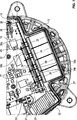
Der Motor
Der Motor
Der Rotor
Der Motorträger
An seiner Vorderseite ist der Rotor
Im in
Die Dichtelemente
Wie aus
Wie aus den
Wie aus
Wie aus den
Die
Der Schneidklemmkontakt
So schließt sich an die Einsteckzone E eine Vorschneidezone V an. Innerhalb der Vorschneidezone V ist die Schneidklemmkante
An die Vorschneidezone V schließt sich eine Abreibzone A an. Innerhalb dieser Abreibzone verläuft die Schneidklemmkante
An die Abreibzone A schließt sich in Schneidklemmrichtung
Der Elektromotor
Bei diesem Elektromotor
Zusätzlich in die Leiterplatte
Der diesbezügliche Elektromotor
Der Elektromotor
Claims (6)
Priority Applications (9)
| Application Number | Priority Date | Filing Date | Title |
|---|---|---|---|
| DE102011112821A DE102011112821B4 (en) | 2011-09-12 | 2011-09-12 | Electric motor, in particular radiator fan motor |
| PCT/EP2012/003576 WO2013037452A2 (en) | 2011-09-12 | 2012-08-24 | Electric motor, in particular a radiator fan motor |
| BR112014005782A BR112014005782A2 (en) | 2011-09-12 | 2012-08-24 | electric motor, especially radiator fan motor |
| CN201280044382.7A CN104145406B (en) | 2011-09-12 | 2012-08-24 | Motor, especially radiator fan motor |
| KR1020147006659A KR101558313B1 (en) | 2011-09-12 | 2012-08-24 | Electric motor |
| EP12761892.4A EP2756583B1 (en) | 2011-09-12 | 2012-08-24 | Electric motor, in particular a radiator fan motor |
| ES12761892T ES2762197T3 (en) | 2011-09-12 | 2012-08-24 | Electric motor, in particular radiator fan motor |
| US14/206,307 US9590323B2 (en) | 2011-09-12 | 2014-03-12 | Electric motor, in particular a radiator fan motor, and a contact |
| US15/403,406 US9899754B2 (en) | 2011-09-12 | 2017-01-11 | Insulation-displacement contact |
Applications Claiming Priority (1)
| Application Number | Priority Date | Filing Date | Title |
|---|---|---|---|
| DE102011112821A DE102011112821B4 (en) | 2011-09-12 | 2011-09-12 | Electric motor, in particular radiator fan motor |
Publications (2)
| Publication Number | Publication Date |
|---|---|
| DE102011112821A1 DE102011112821A1 (en) | 2013-03-14 |
| DE102011112821B4 true DE102011112821B4 (en) | 2013-06-27 |
Family
ID=46888361
Family Applications (1)
| Application Number | Title | Priority Date | Filing Date |
|---|---|---|---|
| DE102011112821A Expired - Fee Related DE102011112821B4 (en) | 2011-09-12 | 2011-09-12 | Electric motor, in particular radiator fan motor |
Country Status (8)
| Country | Link |
|---|---|
| US (2) | US9590323B2 (en) |
| EP (1) | EP2756583B1 (en) |
| KR (1) | KR101558313B1 (en) |
| CN (1) | CN104145406B (en) |
| BR (1) | BR112014005782A2 (en) |
| DE (1) | DE102011112821B4 (en) |
| ES (1) | ES2762197T3 (en) |
| WO (1) | WO2013037452A2 (en) |
Cited By (3)
| Publication number | Priority date | Publication date | Assignee | Title |
|---|---|---|---|---|
| DE102017209621A1 (en) * | 2017-06-08 | 2018-12-13 | Robert Bosch Gmbh | Drive unit with an electronically commutated motor and an electronics unit |
| DE102022203218A1 (en) | 2022-03-31 | 2023-10-05 | Brose Fahrzeugteile SE & Co. Kommanditgesellschaft, Würzburg | Electric motor and radiator fan with such an electric motor |
| DE102022129216A1 (en) * | 2022-11-04 | 2024-05-08 | Audi Aktiengesellschaft | Electric machine with associated pulse inverter |
Families Citing this family (33)
| Publication number | Priority date | Publication date | Assignee | Title |
|---|---|---|---|---|
| DE102011112821B4 (en) * | 2011-09-12 | 2013-06-27 | Brose Fahrzeugteile GmbH & Co. Kommanditgesellschaft, Würzburg | Electric motor, in particular radiator fan motor |
| ITBO20120682A1 (en) * | 2012-12-18 | 2014-06-19 | Spal Automotive Srl | ELECTRIC MACHINE |
| US10208853B2 (en) | 2015-02-27 | 2019-02-19 | Brose Fahrzeugteile Gmbh & Co. Kommanditgesellschaft, Wuerzburg | Motor assembly |
| DE102015217020B4 (en) * | 2015-09-04 | 2025-06-12 | Brose Fahrzeugteile SE & Co. Kommanditgesellschaft, Würzburg | Engine assembly |
| CN106033928B (en) * | 2015-03-19 | 2019-04-12 | 台达电子工业股份有限公司 | power supply filter |
| JP6566711B2 (en) * | 2015-05-08 | 2019-08-28 | 日立ジョンソンコントロールズ空調株式会社 | Air conditioner |
| DE102015210420A1 (en) * | 2015-06-08 | 2016-12-08 | Robert Bosch Gmbh | Electrically commutated electric motor and comfort drive with an electric motor |
| DE102015220432B4 (en) | 2015-10-20 | 2020-01-09 | Lisa Dräxlmaier GmbH | Secured insulation displacement connector and printed circuit board equipped with it |
| DE102017002865B4 (en) | 2016-03-24 | 2021-07-29 | Minebea Mitsumi Inc. | Structure of an axial fan |
| FR3054745B1 (en) * | 2016-08-01 | 2021-10-15 | Valeo Equip Electr Moteur | ROTATING ELECTRIC MACHINE EQUIPPED WITH AN INTERCONNECTOR WITH SCREWING HOOKS |
| DE102017207104A1 (en) * | 2017-04-27 | 2018-10-31 | Robert Bosch Gmbh | Electronically commutated motor |
| US11146148B2 (en) * | 2017-06-30 | 2021-10-12 | Hanon Systems | BLDC motor integrated with inverter |
| DE102017212595A1 (en) * | 2017-07-21 | 2019-01-24 | Robert Bosch Gmbh | Inverter for an electric machine |
| WO2019022110A1 (en) * | 2017-07-28 | 2019-01-31 | 日本電産トーソク株式会社 | Motor |
| JP6644038B2 (en) * | 2017-09-13 | 2020-02-12 | シナノケンシ株式会社 | Blower |
| DE112018005849B4 (en) * | 2017-11-15 | 2022-09-01 | KYOCERA AVX Components Corporation | Cable connector with IDC connection contact for built-in strain relief |
| DE102018200480A1 (en) * | 2018-01-12 | 2019-07-18 | Mahle International Gmbh | Control device for driving an electric motor |
| DE102018202408A1 (en) * | 2018-02-16 | 2019-08-22 | Bühler Motor GmbH | STATOR WITH A WINDING SWITCHING |
| TWI676339B (en) * | 2018-03-20 | 2019-11-01 | 元山科技工業股份有限公司 | electric motor |
| US11362444B2 (en) | 2018-06-27 | 2022-06-14 | Interplex Industries, Inc. | Laminated wire connector |
| CN109450182A (en) * | 2018-12-25 | 2019-03-08 | 上海盘毂动力科技股份有限公司 | Integrated electric motor and integrated electric motor assembly method |
| DE102019104706A1 (en) * | 2019-02-25 | 2020-08-27 | Nidec Gpm Gmbh | Electrical contacting of stator connections on a printed circuit board by means of horizontally aligned insulation displacement contacts |
| DE102019104705A1 (en) | 2019-02-25 | 2020-08-27 | Nidec Gpm Gmbh | Electrical contacting of the stator connections on the PCB by means of a crimp connection |
| WO2021155890A1 (en) * | 2020-02-07 | 2021-08-12 | Brose Fahrzeugteile SE & Co. Kommanditgesellschaft, Würzburg | Electrical machine of a motor vehicle |
| LU101924B1 (en) * | 2020-07-13 | 2022-01-13 | Adcos Gmbh | Drive device, in particular for a compressor system for generating compressed air in a vehicle brake |
| US11520386B2 (en) * | 2021-03-26 | 2022-12-06 | Lenovo (Singapore) Pte. Ltd. | Fan motor for wireless charging |
| DE102021209722A1 (en) * | 2021-09-03 | 2023-03-09 | Brose Fahrzeugteile SE & Co. Kommanditgesellschaft, Würzburg | Electric motor vehicle fan drive |
| FR3128816A1 (en) * | 2021-11-03 | 2023-05-05 | Valeo Systemes Thermiques | ELECTRIC CONNECTOR FOR ELECTRIC MOTOR |
| DE102022103550B4 (en) * | 2022-02-15 | 2024-01-04 | Woco Gmbh & Co. Kg | Control circuit for an electrical separator |
| DE102022207990A1 (en) * | 2022-08-02 | 2024-02-08 | Brose Fahrzeugteile SE & Co. Kommanditgesellschaft, Würzburg | Electromotive refrigerant compressor |
| CN115514127A (en) * | 2022-08-30 | 2022-12-23 | 上海马陆日用友捷汽车电气有限公司 | A low power permanent magnet brushless DC motor for automobile radiator fan |
| JP2024095304A (en) * | 2022-12-28 | 2024-07-10 | ニデックパワートレインシステムズ株式会社 | Motors and pumps |
| KR102761273B1 (en) * | 2023-07-04 | 2025-01-31 | 강기철 | Multi-Phase and Independent Parallel Connection Dc motor with coils wound in parallel according to the poles of the rotor |
Citations (2)
| Publication number | Priority date | Publication date | Assignee | Title |
|---|---|---|---|---|
| DE19736119A1 (en) * | 1997-08-20 | 1999-03-11 | Lumberg Karl Gmbh & Co | Insulation cutting clamp |
| WO2002087057A1 (en) * | 2001-04-20 | 2002-10-31 | Robert Bosch Gmbh | Electronically commutated direct current motor |
Family Cites Families (25)
| Publication number | Priority date | Publication date | Assignee | Title |
|---|---|---|---|---|
| US4116522A (en) * | 1976-07-09 | 1978-09-26 | Amp Incorporated | Slotted terminal |
| NZ193872A (en) * | 1979-06-29 | 1982-12-07 | Amp Inc | Electrical contact member and incorporated connector |
| DE3214896C1 (en) * | 1982-04-22 | 1983-10-06 | Krone Gmbh | Connection element for cable cores and Dopwire cables |
| US4553808A (en) * | 1983-12-23 | 1985-11-19 | Amp Incorporated | Electrical terminal intended for mating with a terminal tab |
| JPS6464285A (en) * | 1987-09-03 | 1989-03-10 | Kyushu Nippon Electric | Printed board |
| JPH02302087A (en) * | 1989-05-16 | 1990-12-14 | Seiko Epson Corp | Leak-proof board structure |
| US5610458A (en) * | 1994-05-11 | 1997-03-11 | Emerson Electric Co. | Electrical connection of printed circuit board to line leads on brushless permanent magnet refrigeration motors |
| FR2750542B1 (en) * | 1996-06-27 | 1998-10-02 | Ecia Equip Composants Ind Auto | ELECTRICAL CONNECTION DEVICE FOR DIRECT CURRENT MOTOR |
| US5783872A (en) * | 1996-07-25 | 1998-07-21 | Northrop Grumman Corporation | Auxiliary battery voltage/temperature compensation for automotive 12 volt system for electric vehicles |
| JPH10228932A (en) | 1997-02-13 | 1998-08-25 | Honda Motor Co Ltd | Structure of insulation displacement terminal |
| DE19848039A1 (en) * | 1998-10-17 | 2000-04-20 | Bosch Gmbh Robert | Arrangement for contacting component with electrical connection has electric circuit slotted connector with which electric circuit is plugged onto electrical connector on component |
| JP3690197B2 (en) * | 1999-08-03 | 2005-08-31 | 住友電装株式会社 | Method for manufacturing joint member |
| US6297572B1 (en) * | 1999-08-24 | 2001-10-02 | Calsonic Kansei Corporation | Brushless motor |
| AU784125B2 (en) * | 2000-12-06 | 2006-02-09 | Robert Bosch Gmbh | Connector for an electric motor |
| DE10063323C2 (en) * | 2000-12-19 | 2003-05-08 | Hella Kg Hueck & Co | Brake light as LED circuit board in a splash-proof housing |
| US6524127B2 (en) * | 2001-06-18 | 2003-02-25 | Illinois Tool Works | Insulation displacement connector with reversed bevel cutting edge contacts |
| DE10140275A1 (en) * | 2001-08-16 | 2003-03-06 | Hella Kg Hueck & Co | Motor vehicle light, circuit arrangement for a motor vehicle light and circuit board for a motor vehicle light |
| JP4851309B2 (en) * | 2006-12-06 | 2012-01-11 | 矢崎総業株式会社 | Lighting device |
| DE102008033905A1 (en) * | 2008-07-18 | 2010-01-21 | Wago Verwaltungsgesellschaft Mbh | Conductor connection element for attaching electrical conductor, has sharp-edged insulation cuts that are aligned at angle which is less than angle at which contact-cuts are aligned with respect to longitudinal extension axis of slot |
| US8436711B2 (en) * | 2008-11-28 | 2013-05-07 | Osram Gesellschaft Mit Beschrankter Haftung | Integrated gas discharge lamp and ignition transformer for an integrated gas discharge lamp |
| DE102010000710A1 (en) * | 2010-01-07 | 2011-07-14 | Robert Bosch GmbH, 70469 | end shield |
| DE102011112821B4 (en) * | 2011-09-12 | 2013-06-27 | Brose Fahrzeugteile GmbH & Co. Kommanditgesellschaft, Würzburg | Electric motor, in particular radiator fan motor |
| EP2747206B1 (en) * | 2011-10-14 | 2018-07-18 | Omron Corporation | Terminal |
| FR2985597B1 (en) * | 2012-01-05 | 2014-10-24 | Valeo Equip Electr Moteur | CAPACITY ASSEMBLY DEVICE FOR ELECTRONIC CONVERTER |
| US8911250B2 (en) * | 2012-10-05 | 2014-12-16 | Facebook, Inc. | Floating bus bar connector |
-
2011
- 2011-09-12 DE DE102011112821A patent/DE102011112821B4/en not_active Expired - Fee Related
-
2012
- 2012-08-24 ES ES12761892T patent/ES2762197T3/en active Active
- 2012-08-24 CN CN201280044382.7A patent/CN104145406B/en active Active
- 2012-08-24 BR BR112014005782A patent/BR112014005782A2/en not_active Application Discontinuation
- 2012-08-24 EP EP12761892.4A patent/EP2756583B1/en active Active
- 2012-08-24 KR KR1020147006659A patent/KR101558313B1/en active Active
- 2012-08-24 WO PCT/EP2012/003576 patent/WO2013037452A2/en not_active Ceased
-
2014
- 2014-03-12 US US14/206,307 patent/US9590323B2/en active Active
-
2017
- 2017-01-11 US US15/403,406 patent/US9899754B2/en active Active
Patent Citations (2)
| Publication number | Priority date | Publication date | Assignee | Title |
|---|---|---|---|---|
| DE19736119A1 (en) * | 1997-08-20 | 1999-03-11 | Lumberg Karl Gmbh & Co | Insulation cutting clamp |
| WO2002087057A1 (en) * | 2001-04-20 | 2002-10-31 | Robert Bosch Gmbh | Electronically commutated direct current motor |
Cited By (3)
| Publication number | Priority date | Publication date | Assignee | Title |
|---|---|---|---|---|
| DE102017209621A1 (en) * | 2017-06-08 | 2018-12-13 | Robert Bosch Gmbh | Drive unit with an electronically commutated motor and an electronics unit |
| DE102022203218A1 (en) | 2022-03-31 | 2023-10-05 | Brose Fahrzeugteile SE & Co. Kommanditgesellschaft, Würzburg | Electric motor and radiator fan with such an electric motor |
| DE102022129216A1 (en) * | 2022-11-04 | 2024-05-08 | Audi Aktiengesellschaft | Electric machine with associated pulse inverter |
Also Published As
| Publication number | Publication date |
|---|---|
| WO2013037452A3 (en) | 2014-05-15 |
| WO2013037452A2 (en) | 2013-03-21 |
| ES2762197T3 (en) | 2020-05-22 |
| CN104145406B (en) | 2018-01-02 |
| BR112014005782A2 (en) | 2017-03-28 |
| KR101558313B1 (en) | 2015-10-07 |
| US9590323B2 (en) | 2017-03-07 |
| EP2756583B1 (en) | 2019-10-30 |
| US20140191598A1 (en) | 2014-07-10 |
| KR20140056338A (en) | 2014-05-09 |
| DE102011112821A1 (en) | 2013-03-14 |
| EP2756583A2 (en) | 2014-07-23 |
| US20170125928A1 (en) | 2017-05-04 |
| US9899754B2 (en) | 2018-02-20 |
| CN104145406A (en) | 2014-11-12 |
Similar Documents
| Publication | Publication Date | Title |
|---|---|---|
| DE102011112821B4 (en) | Electric motor, in particular radiator fan motor | |
| EP1384307B2 (en) | Electronically commutated direct current motor | |
| DE102016224526B4 (en) | Stator of an electrical machine, electrical machine and laying and contact device for an electrical machine | |
| DE102013020094B4 (en) | Electric motor, in particular radiator fan motor | |
| DE112010006096B4 (en) | Stator and rotating electrical machine equipped with this stator | |
| EP1689065B1 (en) | Stator for an electric motor and its manufacturing process | |
| DE29516656U1 (en) | Brushless electric motor | |
| EP3078099B1 (en) | Stator for an electronically commutated direct current motor | |
| DE102013003024A1 (en) | Electric motor, in particular a vehicle component | |
| DE102011112817A1 (en) | Electric motor, in particular radiator fan motor | |
| EP2182616A2 (en) | Brushless DC motor | |
| DE202015008207U1 (en) | Stator of an electric motor and switching unit for this | |
| WO2016008827A2 (en) | Stator of an electric motor and contact system therefor | |
| DE10130117A1 (en) | Housing cover for an electric motor, in particular for an electronically commutated direct current motor | |
| WO2024218052A1 (en) | Electric motor and refrigerant compressor comprising such an electric motor | |
| EP2342799B1 (en) | Electrical machine having a contact element for electrically connecting electrical components | |
| DE102018116930A1 (en) | Stator for a DC machine and method for producing such a stator | |
| WO2022179658A1 (en) | Wiring ring, stator and electric machine | |
| DE102014209677A1 (en) | End shield for an electrical machine | |
| DE102016220269A1 (en) | electric motor | |
| DE102023202363A1 (en) | Electrical machine with a one-piece interconnection device and method for assembling the electrical machine | |
| WO2026082869A1 (en) | Electric motor, in particular brushless dc motor | |
| DE102023201624A1 (en) | Electric motor, especially radiator fan motor | |
| EP2502333A2 (en) | Arrangement of an actuation circuit in an electrical machine | |
| DE102015102349A1 (en) | Stator with toroidal stator winding |
Legal Events
| Date | Code | Title | Description |
|---|---|---|---|
| R012 | Request for examination validly filed | ||
| R016 | Response to examination communication | ||
| R016 | Response to examination communication | ||
| R016 | Response to examination communication | ||
| R016 | Response to examination communication | ||
| R018 | Grant decision by examination section/examining division | ||
| R020 | Patent grant now final |
Effective date: 20130928 |
|
| R081 | Change of applicant/patentee |
Owner name: BROSE FAHRZEUGTEILE SE & CO. KOMMANDITGESELLSC, DE Free format text: FORMER OWNER: BROSE FAHRZEUGTEILE GMBH & CO. KOMMANDITGESELLSCHAFT, WUERZBURG, 97076 WUERZBURG, DE |
|
| R082 | Change of representative |
Representative=s name: FDST PATENTANWAELTE FREIER DOERR STAMMLER TSCH, DE |
|
| R119 | Application deemed withdrawn, or ip right lapsed, due to non-payment of renewal fee |