DE102011087174A1 - VEHICLE SEAT - Google Patents
VEHICLE SEAT Download PDFInfo
- Publication number
- DE102011087174A1 DE102011087174A1 DE102011087174A DE102011087174A DE102011087174A1 DE 102011087174 A1 DE102011087174 A1 DE 102011087174A1 DE 102011087174 A DE102011087174 A DE 102011087174A DE 102011087174 A DE102011087174 A DE 102011087174A DE 102011087174 A1 DE102011087174 A1 DE 102011087174A1
- Authority
- DE
- Germany
- Prior art keywords
- link
- lever
- actuating
- vehicle seat
- links
- Prior art date
- Legal status (The legal status is an assumption and is not a legal conclusion. Google has not performed a legal analysis and makes no representation as to the accuracy of the status listed.)
- Granted
Links
Images






Classifications
-
- G—PHYSICS
- G05—CONTROLLING; REGULATING
- G05G—CONTROL DEVICES OR SYSTEMS INSOFAR AS CHARACTERISED BY MECHANICAL FEATURES ONLY
- G05G9/00—Manually-actuated control mechanisms provided with one single controlling member co-operating with two or more controlled members, e.g. selectively, simultaneously
- G05G9/08—Manually-actuated control mechanisms provided with one single controlling member co-operating with two or more controlled members, e.g. selectively, simultaneously the controlled members being actuated successively by progressive movement of the controlling member
-
- B—PERFORMING OPERATIONS; TRANSPORTING
- B60—VEHICLES IN GENERAL
- B60N—SEATS SPECIALLY ADAPTED FOR VEHICLES; VEHICLE PASSENGER ACCOMMODATION NOT OTHERWISE PROVIDED FOR
- B60N2/00—Seats specially adapted for vehicles; Arrangement or mounting of seats in vehicles
- B60N2/02—Seats specially adapted for vehicles; Arrangement or mounting of seats in vehicles the seat or part thereof being movable, e.g. adjustable
- B60N2/0296—Central command actuator to selectively switch on or engage one of several special purpose circuits or mechanisms
-
- B—PERFORMING OPERATIONS; TRANSPORTING
- B60—VEHICLES IN GENERAL
- B60N—SEATS SPECIALLY ADAPTED FOR VEHICLES; VEHICLE PASSENGER ACCOMMODATION NOT OTHERWISE PROVIDED FOR
- B60N2/00—Seats specially adapted for vehicles; Arrangement or mounting of seats in vehicles
- B60N2/02—Seats specially adapted for vehicles; Arrangement or mounting of seats in vehicles the seat or part thereof being movable, e.g. adjustable
- B60N2/04—Seats specially adapted for vehicles; Arrangement or mounting of seats in vehicles the seat or part thereof being movable, e.g. adjustable the whole seat being movable
- B60N2/06—Seats specially adapted for vehicles; Arrangement or mounting of seats in vehicles the seat or part thereof being movable, e.g. adjustable the whole seat being movable slidable
- B60N2/062—Seats specially adapted for vehicles; Arrangement or mounting of seats in vehicles the seat or part thereof being movable, e.g. adjustable the whole seat being movable slidable transversally slidable
-
- B—PERFORMING OPERATIONS; TRANSPORTING
- B60—VEHICLES IN GENERAL
- B60N—SEATS SPECIALLY ADAPTED FOR VEHICLES; VEHICLE PASSENGER ACCOMMODATION NOT OTHERWISE PROVIDED FOR
- B60N2/00—Seats specially adapted for vehicles; Arrangement or mounting of seats in vehicles
- B60N2/02—Seats specially adapted for vehicles; Arrangement or mounting of seats in vehicles the seat or part thereof being movable, e.g. adjustable
- B60N2/04—Seats specially adapted for vehicles; Arrangement or mounting of seats in vehicles the seat or part thereof being movable, e.g. adjustable the whole seat being movable
- B60N2/06—Seats specially adapted for vehicles; Arrangement or mounting of seats in vehicles the seat or part thereof being movable, e.g. adjustable the whole seat being movable slidable
- B60N2/065—Rear seats
-
- B—PERFORMING OPERATIONS; TRANSPORTING
- B60—VEHICLES IN GENERAL
- B60N—SEATS SPECIALLY ADAPTED FOR VEHICLES; VEHICLE PASSENGER ACCOMMODATION NOT OTHERWISE PROVIDED FOR
- B60N2/00—Seats specially adapted for vehicles; Arrangement or mounting of seats in vehicles
- B60N2/02—Seats specially adapted for vehicles; Arrangement or mounting of seats in vehicles the seat or part thereof being movable, e.g. adjustable
- B60N2/04—Seats specially adapted for vehicles; Arrangement or mounting of seats in vehicles the seat or part thereof being movable, e.g. adjustable the whole seat being movable
- B60N2/06—Seats specially adapted for vehicles; Arrangement or mounting of seats in vehicles the seat or part thereof being movable, e.g. adjustable the whole seat being movable slidable
- B60N2/07—Slide construction
- B60N2/0702—Slide construction characterised by its cross-section
- B60N2/0705—Slide construction characterised by its cross-section omega-shaped
-
- B—PERFORMING OPERATIONS; TRANSPORTING
- B60—VEHICLES IN GENERAL
- B60N—SEATS SPECIALLY ADAPTED FOR VEHICLES; VEHICLE PASSENGER ACCOMMODATION NOT OTHERWISE PROVIDED FOR
- B60N2/00—Seats specially adapted for vehicles; Arrangement or mounting of seats in vehicles
- B60N2/02—Seats specially adapted for vehicles; Arrangement or mounting of seats in vehicles the seat or part thereof being movable, e.g. adjustable
- B60N2/04—Seats specially adapted for vehicles; Arrangement or mounting of seats in vehicles the seat or part thereof being movable, e.g. adjustable the whole seat being movable
- B60N2/06—Seats specially adapted for vehicles; Arrangement or mounting of seats in vehicles the seat or part thereof being movable, e.g. adjustable the whole seat being movable slidable
- B60N2/07—Slide construction
- B60N2/0702—Slide construction characterised by its cross-section
- B60N2/0715—C or U-shaped
-
- B—PERFORMING OPERATIONS; TRANSPORTING
- B60—VEHICLES IN GENERAL
- B60N—SEATS SPECIALLY ADAPTED FOR VEHICLES; VEHICLE PASSENGER ACCOMMODATION NOT OTHERWISE PROVIDED FOR
- B60N2/00—Seats specially adapted for vehicles; Arrangement or mounting of seats in vehicles
- B60N2/02—Seats specially adapted for vehicles; Arrangement or mounting of seats in vehicles the seat or part thereof being movable, e.g. adjustable
- B60N2/04—Seats specially adapted for vehicles; Arrangement or mounting of seats in vehicles the seat or part thereof being movable, e.g. adjustable the whole seat being movable
- B60N2/06—Seats specially adapted for vehicles; Arrangement or mounting of seats in vehicles the seat or part thereof being movable, e.g. adjustable the whole seat being movable slidable
- B60N2/08—Seats specially adapted for vehicles; Arrangement or mounting of seats in vehicles the seat or part thereof being movable, e.g. adjustable the whole seat being movable slidable characterised by the locking device
- B60N2/0812—Location of the latch
- B60N2/0818—Location of the latch inside the rail
-
- B—PERFORMING OPERATIONS; TRANSPORTING
- B60—VEHICLES IN GENERAL
- B60N—SEATS SPECIALLY ADAPTED FOR VEHICLES; VEHICLE PASSENGER ACCOMMODATION NOT OTHERWISE PROVIDED FOR
- B60N2/00—Seats specially adapted for vehicles; Arrangement or mounting of seats in vehicles
- B60N2/02—Seats specially adapted for vehicles; Arrangement or mounting of seats in vehicles the seat or part thereof being movable, e.g. adjustable
- B60N2/04—Seats specially adapted for vehicles; Arrangement or mounting of seats in vehicles the seat or part thereof being movable, e.g. adjustable the whole seat being movable
- B60N2/06—Seats specially adapted for vehicles; Arrangement or mounting of seats in vehicles the seat or part thereof being movable, e.g. adjustable the whole seat being movable slidable
- B60N2/08—Seats specially adapted for vehicles; Arrangement or mounting of seats in vehicles the seat or part thereof being movable, e.g. adjustable the whole seat being movable slidable characterised by the locking device
- B60N2/0831—Movement of the latch
- B60N2/0837—Movement of the latch pivoting
- B60N2/0843—Movement of the latch pivoting about a longitudinal axis
-
- B—PERFORMING OPERATIONS; TRANSPORTING
- B60—VEHICLES IN GENERAL
- B60N—SEATS SPECIALLY ADAPTED FOR VEHICLES; VEHICLE PASSENGER ACCOMMODATION NOT OTHERWISE PROVIDED FOR
- B60N2/00—Seats specially adapted for vehicles; Arrangement or mounting of seats in vehicles
- B60N2/02—Seats specially adapted for vehicles; Arrangement or mounting of seats in vehicles the seat or part thereof being movable, e.g. adjustable
- B60N2/04—Seats specially adapted for vehicles; Arrangement or mounting of seats in vehicles the seat or part thereof being movable, e.g. adjustable the whole seat being movable
- B60N2/12—Seats specially adapted for vehicles; Arrangement or mounting of seats in vehicles the seat or part thereof being movable, e.g. adjustable the whole seat being movable slidable and tiltable
-
- B—PERFORMING OPERATIONS; TRANSPORTING
- B60—VEHICLES IN GENERAL
- B60N—SEATS SPECIALLY ADAPTED FOR VEHICLES; VEHICLE PASSENGER ACCOMMODATION NOT OTHERWISE PROVIDED FOR
- B60N2/00—Seats specially adapted for vehicles; Arrangement or mounting of seats in vehicles
- B60N2/90—Details or parts not otherwise provided for
- B60N2/919—Positioning and locking mechanisms
-
- Y—GENERAL TAGGING OF NEW TECHNOLOGICAL DEVELOPMENTS; GENERAL TAGGING OF CROSS-SECTIONAL TECHNOLOGIES SPANNING OVER SEVERAL SECTIONS OF THE IPC; TECHNICAL SUBJECTS COVERED BY FORMER USPC CROSS-REFERENCE ART COLLECTIONS [XRACs] AND DIGESTS
- Y10—TECHNICAL SUBJECTS COVERED BY FORMER USPC
- Y10T—TECHNICAL SUBJECTS COVERED BY FORMER US CLASSIFICATION
- Y10T74/00—Machine element or mechanism
- Y10T74/20—Control lever and linkage systems
- Y10T74/20012—Multiple controlled elements
Landscapes
- Engineering & Computer Science (AREA)
- Aviation & Aerospace Engineering (AREA)
- Transportation (AREA)
- Mechanical Engineering (AREA)
- Physics & Mathematics (AREA)
- General Physics & Mathematics (AREA)
- Automation & Control Theory (AREA)
- Seats For Vehicles (AREA)
Abstract
Die Erfindung betrifft einen Fahrzeugsitz mit einem Steuermechanismus (Entriegelungsmechanismus) (10), der einen durch einen Bedienhebel (7) angetriebenen Betätigungsstift (Betätigungsmechanismus) (12), ein durch den Betätigungsstift (12) angetriebenes erstes Verbindungsglied (14) zum Entriegeln eines Längsverstellmechanismus (4) und ein angetriebenes zweites Verbindungsglied (15) zum Entriegeln eines Querverstellmechanismus (5) umfasst. An jedem der Verbindungsglieder (14, 15) sind nebeneinander ein Übertragungsabschnitt (14B, 15B), der eine durch den Betätigungsstift (12) übertragene Antriebskraft des Hebels (7) aufnimmt und die Antriebskraft auf einen Verriegelungsstruktur der Verstellmechanismen (4, 5) überträgt, und ein Entlastungsabschnitt (14C, 15C), der die Übertragung der Antriebskraft vom Betätigungsstift (12) unterbricht, ausgebildet. Die Übertragung der Antriebskraft vom Hebel (7) über den Betätigungsstift (12) auf die Verbindungsglieder (14, 15) kann während der Betätigung unterbrochen werden.The invention relates to a vehicle seat with a control mechanism (unlocking mechanism) (10) which has an actuating pin (actuating mechanism) (12) driven by an operating lever (7), a first connecting member (14) driven by the actuating pin (12) for unlocking a longitudinal adjustment mechanism ( 4) and a driven second connecting member (15) for unlocking a transverse adjustment mechanism (5). On each of the connecting links (14, 15) there are next to one another a transmission section (14B, 15B) which receives a drive force of the lever (7) transmitted through the actuating pin (12) and transmits the drive force to a locking structure of the adjustment mechanisms (4, 5), and a relief portion (14C, 15C) which interrupts the transmission of the driving force from the operating pin (12) is formed. The transmission of the drive force from the lever (7) via the actuating pin (12) to the connecting links (14, 15) can be interrupted during actuation.
Description
TECHNOLOGISCHER HINTERGRUND DER ERFINDUNGTECHNOLOGICAL BACKGROUND OF THE INVENTION
1. Technisches Gebiet der Erfindung1. Technical field of the invention
Die Erfindung bezieht sich auf einen Fahrzeugsitz. Die Erfindung bezieht sich im Besonderen auf einen Fahrzeugsitz mit einem Steuermechanismus, der im Ansprechen auf die Bedienung eines einzigen Hebels zwei Mechanismen ansteuert.The invention relates to a vehicle seat. More particularly, the invention relates to a vehicle seat having a control mechanism that controls two mechanisms in response to the operation of a single lever.
2. Stand der Technik2. State of the art
Die
Bei diesem Stand der Technik ist ein Mechanismus vorgesehen, der ermöglicht, dass auf der Seite, auf der die Verriegelung zuerst gelöst wird, auf halbem Weg keine Kraft mehr übertragen wird, wodurch der Mechanismus bei fortschreitender Hebelbedienung insoweit nicht übermäßig belastet wird. Auf der Seite, auf der die Verriegelung später gelöst wird, ist der Mechanismus jedoch so ausgelegt, dass er bei fortschreitender Hebelbedienung weiterhin eine Kraft aufnimmt, obwohl die Verriegelung bereits gelöst ist. Es ist daher nicht so einfach, eine ausreichende Hebelwegtoleranz zu berücksichtigen, was von Nachteil ist.In this prior art, a mechanism is provided which allows on the side on which the lock is first released, no power is transmitted midway, whereby the mechanism is not excessively burdened as the lever operation progresses. On the side on which the lock is released later, however, the mechanism is designed so that it continues to receive a force as the lever operation progresses, even though the lock has already been released. It is therefore not so easy to consider a sufficient lever travel tolerance, which is disadvantageous.
ZUSAMMENFASSUNG DER ERFINDUNGSUMMARY OF THE INVENTION
Hiervon ausgehend liegt der Erfindung die Aufgabe zugrunde, einen Fahrzeugsitz mit einem Steuermechanismus bereitzustellen, der im Ansprechen auf die Bedienung eines einzigen Hebels zwei Mechanismen betätigt, bei dem aber die Mechanismen selbst bei einer ausreichenden Hebelwegtoleranz keine übermäßige Belastung aufgrund der Hebelbedienung erfahren. Diese Aufgabe wird durch einen Fahrzeugsitz mit den Merkmalen des Anspruchs 1 gelöst. Vorteilhafte Weiterbildungen sind Gegenstand abhängiger Ansprüche.Proceeding from this, the present invention seeks to provide a vehicle seat with a control mechanism that operates in response to the operation of a single lever two mechanisms, but in which the mechanisms do not experience excessive load due to the lever operation even with a sufficient lever travel tolerance. This object is achieved by a vehicle seat with the features of
Ein erfindungsgemäßer Fahrzeugsitz hat einen Steuermechanismus, der im Ansprechen auf die Bedienung eines Hebels einen ersten Mechanismus und einen zweiten Mechanismus steuert. Der Steuermechanismus umfasst einen durch den Hebel betätigten Betätigungsmechanismus, ein durch den Betätigungsmechanismus angetriebenes erstes Verbindungsglied zur Betätigung des ersten Mechanismus und ein durch den Betätigungsmechanismus angetriebenes zweites Verbindungsglied zur Betätigung des zweiten Mechanismus. An jeden der Verbindungsglieder sind nebeneinander ein Übertragungsabschnitt, der die die über den Betätigungsmechanismus übertragene Antriebskraft des Hebels aufnimmt und auf den ersten und zweiten Mechanismus überträgt, und ein Entlastungsabschnitt, der die Übertragung der Antriebskraft des Betätigungsmechanismus unterbricht, ausgebildet, wobei die Kraftübertragung vom Hebel auf jedes der beiden Verbindungsglieder über den Betätigungsmechanismus während eines Betätigungszustands unterbrochen wird.An inventive vehicle seat has a control mechanism that controls a first mechanism and a second mechanism in response to operation of a lever. The control mechanism includes a lever actuated actuating mechanism, a first link driven by the actuating mechanism for actuating the first mechanism, and a second link driven by the actuating mechanism for actuating the second mechanism. Adjacent to each of the links, there are formed a transmission portion which receives and transmits the driving force of the lever transmitted through the operating mechanism to the first and second mechanisms, and a relief portion which stops transmitting the driving force of the actuating mechanism, the power transmission from the lever each of the two links is interrupted via the actuating mechanism during an actuation state.
Bei dem so aufgebauten Fahrzeugsitz, bei dem jedes der Verbindungsglieder nebeneinander den Übertragungsabschnitt und den Entlastungsabschnitt aufweist und ermöglicht, dass die Kraftübertragung vom Hebel auf die Verbindungsglieder auf halbem Weg unterbrochen wird, kann nach einer erfolgten Betätigung der Mechanismen die Übertragung der Antriebskraft des Hebels unterbrochen werden, so dass die Antriebskraft nicht mehr auf die Verbindungsglieder wirkt. Selbst bei einer großen Hebelwegtoleranz werden die Mechanismen durch die Bedienung des Hebels daher nicht übermäßig belastet.With the vehicle seat thus constructed, in which each of the links side by side has the transmission portion and the relief portion and allows the power transmission from the lever to the links to be interrupted halfway, after a successful operation of the mechanisms, the transmission of the driving force of the lever can be interrupted , so that the driving force no longer acts on the connecting links. Even with a large lever travel tolerance, the mechanisms are therefore not excessively burdened by the operation of the lever.
Die Verbindungsglieder können um eine gemeinsame Achse schwenkbeweglich gelagert sein.The connecting members may be pivotably mounted about a common axis.
Diese Weiterbildung, bei der die Verbindungsglieder um eine gemeinsame Achse schwenkbeweglich sind, können der Übertragungsabschnitt und Entlastungsabschnitt jeweils in radialer Richtung nacheinander oder in Reihe und damit lokal zusammengefasst angeordnet werden und zwar so, dass mittels eines einzigen Steuermechanismus entweder beide Verbindungsglieder verschwenkt werden oder die Übertragung der Antriebskraft unterbrochen wird und eine weitere Schwenkbewegung der beiden Verbindungsglieder unterbleibt. Im Ergebnis kann der Aufbau sehr kompakt gehalten werden.This development, in which the connecting members are pivotable about a common axis, the transmission section and relief section can be arranged successively in the radial direction or sequentially and thus locally combined in such a way that either both links are pivoted by means of a single control mechanism or the transmission the driving force is interrupted and a further pivotal movement of the two connecting links is omitted. As a result, the structure can be kept very compact.
Des Weiteren kann eine Verbindungsstelle eines mit dem ersten Verbindungsglied verbundenen ersten Seils von der Achse weiter entfernt sein als eine Verbindungsstelle eines mit dem zweiten Verbindungsglied verbundenen zweiten Seils.Furthermore, a connection point of a first cable connected to the first connection member may be further away from the axis than a connection point of a second cable connected to the second connection member.
Bei dieser Weiterbildung kann für denselben Schwenkwinkel des ersten Verbindungsglieds und zweiten Verbindungsglieds für das erste Seil eine längere Wegstrecke als für das zweite Seil realisiert werden.In this development, a longer path than for the second cable can be realized for the same pivot angle of the first link and the second link for the first cable.
Des Weiteren kann der Übertragungsabschnitt jedes der Verbindungsglieder eben oder flach und der Entlastungsabschnitt jedes der Verbindungsglieder kurvenförmig ausgebildet sein.Further, the transmitting portion of each of the connecting members may be flat or flat and the relief portion of each of the connecting members may be curved.
Bei dieser Weiterbildung wird bei einer Verschwenkung des ersten Verbindungsglieds und zweiten Verbindungsglieds, wenn der Betätigungsmechanismus über den flach en Übertragungsabschnitt läuft, eine der Antriebsgröße entsprechende Kraft übertragen, wohingegen keine der Antriebsgröße entsprechende Kraft übertragen wird, wenn der Betätigungsmechanismus über den kurvenförmigen Entlastungsabschnitt läuft. Daher erfahren die Seile und der erste und zweite Mechanismus keine übermäßige Belastung. In this development, upon pivoting of the first link and second link, when the actuating mechanism passes over the flat transmission section, a force corresponding to the drive magnitude is transmitted, whereas no force corresponding to the drive magnitude is transmitted when the actuating mechanism passes over the curved relief section. Therefore, the ropes and the first and second mechanisms do not experience excessive load.
Des Weiteren können die Verbindungsglieder in axialer Richtung Seite an Seite angeordnet sein.Furthermore, the connecting members may be arranged in the axial direction side by side.
Diese Weiterbildung ermöglicht durch die axiale Nebeneinanderanordnung der Verbindungsglieder eine Anordnung der Verbindungsglieder so, dass sich deren Bewegungsbereiche in axialer Richtung überlagern. Im Ergebnis kann der Steuermechanismus in radialer Richtung kompakt gehalten werden.This development allows by the axial juxtaposition of the connecting members an arrangement of the connecting members so that overlap their movement areas in the axial direction. As a result, the control mechanism can be kept compact in the radial direction.
KURZBESCHREIBUNG DER ZEICHNUNGENBRIEF DESCRIPTION OF THE DRAWINGS
Die Merkmale, Vorteile sowie die technische und gewerbliche Anwendbarkeit der Erfindung ergeben sich aus der nachfolgenden, ausführlichen Beschreibung beispielhafter Ausführungsformen der Erfindung mit Hilfe der Zeichnungen, in denen denselben Elementen dieselben Bezugszeichen zugeordnet sind, wobei:The features, advantages and technical and industrial applicability of the invention will become apparent from the following detailed description of exemplary embodiments of the invention with the aid of the drawings, in which the same reference numerals are assigned to the same elements, wherein:
AUSFÜHRLICHE BESCHREIBUNG DER AUSFÜHRUNGSFORMENDETAILED DESCRIPTION OF THE EMBODIMENTS
Im Folgenden wird mit Hilfe der Zeichnungen eine beispielhafte Ausführungsform der Erfindung beschrieben.An exemplary embodiment of the invention will be described below with the aid of the drawings.
Zunächst wird mit Hilfe der
Darüber lassen sich die Längsverstellmechanismen
Als Nächstes wird der Aufbau des Fahrzeugsitzes im Detail beschrieben. Wie es in
Wie es in
Durch die Entriegelung wird die Fixierung des Rückenlehnenwinkels aufgehoben, so dass die Rückenlehne
Wie es in
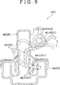
Als nächstes werden die Verriegelungsmechanismen der Längsverstellmechanismen
Als nächstes werden der Aufbau des oben erwähnten Bedienhebels
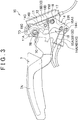
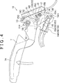
Der Entriegelungsmechanismus
Wie es in
Das T-förmige zweite Verbindungsglied
Das mit dem oben beschriebenen ersten Verbindungsglied
Zwischen einem Haken
Der so ausgebildete Entriegelungsmechanismus
Wenn der Bedienhebel
Auf der in der Zeichnung oberen Kantenfläche des vom Betätigungsstift
Ähnlich dazu sind auf der in der Zeichnung oberen Kantenfläche des vom Betätigungsstift
Wie es in
Bei dem Fahrzeugsitz der beispielhaften Ausführungsform sind die Übertragungsabschnitte
Des Weiteren sind die Verbindungsglieder
Die Erfindung wurde vorstehend an einer beispielhaften Ausführungsform beschrieben, sie kann jedoch auch in einer von der oben beschriebenen beispielhaften Ausführungsform abweichenden Weise ausgeführt werden. Beispielsweise stellt in der oben beschriebenen beispielhaften Ausführungsform der am Bedienhebel
Weiter stellt in der oben beschriebenen beispielhaften Ausführungsform der Mechanismus, durch den im Ansprechen auf eine Bedienung des Entriegelungsmechanismus
ZITATE ENTHALTEN IN DER BESCHREIBUNG QUOTES INCLUDE IN THE DESCRIPTION
Diese Liste der vom Anmelder aufgeführten Dokumente wurde automatisiert erzeugt und ist ausschließlich zur besseren Information des Lesers aufgenommen. Die Liste ist nicht Bestandteil der deutschen Patent- bzw. Gebrauchsmusteranmeldung. Das DPMA übernimmt keinerlei Haftung für etwaige Fehler oder Auslassungen.This list of the documents listed by the applicant has been generated automatically and is included solely for the better information of the reader. The list is not part of the German patent or utility model application. The DPMA assumes no liability for any errors or omissions.
Zitierte PatentliteraturCited patent literature
- JP 2009-292435 A [0002] JP 2009-292435 A [0002]
Claims (5)
Applications Claiming Priority (2)
| Application Number | Priority Date | Filing Date | Title |
|---|---|---|---|
| JP2010264765A JP5591664B2 (en) | 2010-11-29 | 2010-11-29 | Vehicle seat |
| JP2010-264765 | 2010-11-29 |
Publications (2)
| Publication Number | Publication Date |
|---|---|
| DE102011087174A1 true DE102011087174A1 (en) | 2012-05-31 |
| DE102011087174B4 DE102011087174B4 (en) | 2014-04-10 |
Family
ID=46049964
Family Applications (1)
| Application Number | Title | Priority Date | Filing Date |
|---|---|---|---|
| DE102011087174.8A Expired - Fee Related DE102011087174B4 (en) | 2010-11-29 | 2011-11-28 | VEHICLE SEAT |
Country Status (4)
| Country | Link |
|---|---|
| US (2) | US20120132026A1 (en) |
| JP (1) | JP5591664B2 (en) |
| CN (1) | CN102476594B (en) |
| DE (1) | DE102011087174B4 (en) |
Cited By (1)
| Publication number | Priority date | Publication date | Assignee | Title |
|---|---|---|---|---|
| DE102012011508A1 (en) * | 2012-06-09 | 2013-12-12 | GM Global Technology Operations LLC (n. d. Gesetzen des Staates Delaware) | Adjustment device for a vehicle seat, vehicle seat, row of seats, vehicle and method for this purpose |
Families Citing this family (10)
| Publication number | Priority date | Publication date | Assignee | Title |
|---|---|---|---|---|
| EP2874848A1 (en) * | 2012-07-18 | 2015-05-27 | Johnson Controls GmbH | Adjustment unit for a vehicle seat and vehicle seat |
| DE102013215028B4 (en) * | 2013-03-27 | 2018-08-02 | Adient Luxembourg Holding S.À R.L. | Easy entry system for a vehicle seat and vehicle seat |
| CN109435793A (en) * | 2018-09-29 | 2019-03-08 | 延锋安道拓座椅有限公司 | A kind of unlocking mechanism convenient for rear passenger disengaging |
| CN109501641A (en) * | 2018-10-16 | 2019-03-22 | 日照国峤汽车零部件有限公司 | A kind of seat |
| CN111016746A (en) * | 2019-12-17 | 2020-04-17 | 张家港市隆旌汽车零部件有限公司 | A four-way adjustable seat |
| CN113428053B (en) * | 2021-07-15 | 2022-04-01 | 盐城晶心精密机械有限公司 | Electric sliding rail structure of automobile seat |
| JP7849252B2 (en) * | 2022-08-29 | 2026-04-21 | アディエント ユーエス エルエルシー | Vehicle seats |
| US20240255017A1 (en) * | 2023-01-12 | 2024-08-01 | Textron Aviation Inc. | Cable Tension Triggering System |
| CN117261708B (en) * | 2023-05-17 | 2026-03-20 | 一汽奔腾汽车股份有限公司 | A seat escape system and method |
| CN119858489A (en) * | 2025-03-25 | 2025-04-22 | 浙江吉利控股集团有限公司 | Seat adjusting method and device |
Citations (1)
| Publication number | Priority date | Publication date | Assignee | Title |
|---|---|---|---|---|
| JP2009292435A (en) | 2008-06-09 | 2009-12-17 | Toyota Motor Corp | Seat |
Family Cites Families (27)
| Publication number | Priority date | Publication date | Assignee | Title |
|---|---|---|---|---|
| US2918109A (en) * | 1956-08-16 | 1959-12-22 | Anton Lorenz | Adjustable reclining chair |
| US3164407A (en) * | 1960-05-17 | 1965-01-05 | Anton Lorenz | Reclining chair and control arrangement |
| FR1376806A (en) * | 1963-10-12 | 1964-10-31 | Keiper Fritz | Hinge insert for adjustable backrests |
| US4653807A (en) * | 1984-05-18 | 1987-03-31 | Mazda Motor Corporation | Adjustable seat assembly |
| US4834452A (en) * | 1988-07-05 | 1989-05-30 | Goodrich Grover G | Swivel seat and frame |
| FR2747079B1 (en) * | 1996-04-05 | 1998-06-12 | Faure Bertrand Equipements Sa | VEHICLE SEAT, MOVABLE FORWARD TO ACCESS REAR SPACE |
| US5806932A (en) * | 1996-07-25 | 1998-09-15 | P. L. Porter Co. | Seat adjustment and dumping mechanism with memory of adjustment |
| US5813726A (en) * | 1997-02-18 | 1998-09-29 | Hoover Universal, Inc. | Inertia locking device for a vehicle seat adjustment mechanism |
| US5788330A (en) * | 1997-03-27 | 1998-08-04 | Fisher Dynamics Corporation | Seat hinge mechanism with easy entry memory feature |
| US6024398A (en) * | 1998-03-05 | 2000-02-15 | Horton; Fred | Sliding seat assembly for an automobile |
| US6474739B1 (en) * | 2000-10-18 | 2002-11-05 | Duea Global Technologies | Seat track assembly for fold and flip seat |
| DE10052234A1 (en) * | 2000-10-21 | 2002-05-02 | Brose Fahrzeugteile | Motor vehicle car seat adjustment mechanism has a coupling and switching mechanism that allows switching between fixed and adjustment modes that is not placed in the magnetic field of the stepper mechanism |
| FR2824795B1 (en) * | 2001-05-16 | 2004-01-09 | Faurecia Sieges Automobile | CONTROL SYSTEM FOR UNLOCKING THE LINKAGES OF A MOTOR VEHICLE SEAT ON THE FLOOR OF SAID VEHICLE |
| DE10151762B4 (en) * | 2001-10-19 | 2007-08-16 | C. Rob. Hammerstein Gmbh & Co. Kg | Predisplaceable motor vehicle seat with access to a rear seat through a front door |
| JP4206844B2 (en) * | 2003-07-03 | 2009-01-14 | マツダ株式会社 | Vehicle seat device |
| DE102004015450B4 (en) * | 2004-03-30 | 2006-11-30 | Faurecia Autositze Gmbh & Co. Kg | Automotive seat |
| US6935691B1 (en) * | 2004-04-13 | 2005-08-30 | Tachi-S Co., Ltd. | Vehicle seat with seat cushion tip-up structure |
| DE102005020696A1 (en) * | 2005-04-28 | 2006-11-02 | Brose Fahrzeugteile Gmbh & Co. Kommanditgesellschaft, Coburg | Adjustment unit for motor vehicle seat, has operating unit acting on control unit, where operating unit continues rotational movement under deformation of elastic unit when rotational movement of operating unit is prevented by end stop |
| JP4863051B2 (en) * | 2005-11-29 | 2012-01-25 | アイシン精機株式会社 | Vehicle walk-in device |
| JP4182983B2 (en) * | 2006-01-27 | 2008-11-19 | トヨタ自動車株式会社 | Sheet |
| JP4182984B2 (en) * | 2006-01-27 | 2008-11-19 | トヨタ自動車株式会社 | Sheet |
| JP4957990B2 (en) * | 2006-09-19 | 2012-06-20 | テイ・エス テック株式会社 | Arrangement device for automobile seat |
| US8491054B2 (en) * | 2007-01-24 | 2013-07-23 | Johnson Controls Technology Company | Vehicle seat |
| JP2008201235A (en) * | 2007-02-20 | 2008-09-04 | Toyota Boshoku Corp | Unlocking mechanism for vehicle seat |
| WO2011063521A1 (en) * | 2009-11-26 | 2011-06-03 | Magna Seating Inc. | Seat track easy-entry actuation mechanism |
| JP5594092B2 (en) | 2010-11-29 | 2014-09-24 | トヨタ紡織株式会社 | Vehicle seat |
| JP5655574B2 (en) * | 2011-01-07 | 2015-01-21 | アイシン精機株式会社 | Vehicle seat reclining device |
-
2010
- 2010-11-29 JP JP2010264765A patent/JP5591664B2/en active Active
-
2011
- 2011-11-22 US US13/302,204 patent/US20120132026A1/en not_active Abandoned
- 2011-11-28 CN CN201110384815.0A patent/CN102476594B/en not_active Expired - Fee Related
- 2011-11-28 DE DE102011087174.8A patent/DE102011087174B4/en not_active Expired - Fee Related
-
2014
- 2014-08-22 US US14/466,276 patent/US9296318B2/en active Active
Patent Citations (1)
| Publication number | Priority date | Publication date | Assignee | Title |
|---|---|---|---|---|
| JP2009292435A (en) | 2008-06-09 | 2009-12-17 | Toyota Motor Corp | Seat |
Cited By (1)
| Publication number | Priority date | Publication date | Assignee | Title |
|---|---|---|---|---|
| DE102012011508A1 (en) * | 2012-06-09 | 2013-12-12 | GM Global Technology Operations LLC (n. d. Gesetzen des Staates Delaware) | Adjustment device for a vehicle seat, vehicle seat, row of seats, vehicle and method for this purpose |
Also Published As
| Publication number | Publication date |
|---|---|
| US20140360301A1 (en) | 2014-12-11 |
| US9296318B2 (en) | 2016-03-29 |
| US20120132026A1 (en) | 2012-05-31 |
| CN102476594A (en) | 2012-05-30 |
| JP5591664B2 (en) | 2014-09-17 |
| DE102011087174B4 (en) | 2014-04-10 |
| JP2012116210A (en) | 2012-06-21 |
| CN102476594B (en) | 2015-02-25 |
Similar Documents
| Publication | Publication Date | Title |
|---|---|---|
| DE102011087174B4 (en) | VEHICLE SEAT | |
| DE102011087175B4 (en) | VEHICLE SEAT | |
| EP1165342B1 (en) | Automobile seat | |
| EP3325310B1 (en) | Vehicle seat | |
| DE10260826A1 (en) | seat device | |
| DE102011006523A1 (en) | vehicle seat | |
| DE2708423A1 (en) | SEAT CONSTRUCTION FOR ONE VEHICLE | |
| DE202008012706U1 (en) | Lock unit with multipart pawl and spring-loaded locking pawl | |
| WO2002094605A1 (en) | Easy-entry vehicle seat whose seat back releases when returning to a memory position | |
| WO2014075819A1 (en) | Vehicle seat, particularly a motor vehicle seat | |
| DE112015000399B4 (en) | headrest adjustment device | |
| DE102010039465A1 (en) | Vehicle seat with an easy-entry mechanism | |
| DE102006035465B4 (en) | Vehicle boarding device | |
| DE102005039540B4 (en) | Retractable vehicle seat with a base frame and a folding backrest | |
| WO2002094604A2 (en) | Motor vehicle seat | |
| DE102012223791A1 (en) | vehicle seat | |
| DE102024105956A1 (en) | VEHICLE SEAT ACCESS DEVICE | |
| EP3694744B1 (en) | Vehicule seat with easy-entry mechanism | |
| DE102017219708B4 (en) | VEHICLE SEAT | |
| DE102013221928B4 (en) | Vehicle seat with an easy entry system | |
| DE102004040881B4 (en) | vehicle seat | |
| DE102013102224B4 (en) | Locking device for a rail guide of a vehicle seat and rail guide | |
| DE102007029942B4 (en) | Seat height adjustment mechanism | |
| DE10341688B4 (en) | Predisposable vehicle seat with a base and two pairs of rails | |
| DE10341689B4 (en) | Predisposable vehicle seat with a base and two pairs of rails |
Legal Events
| Date | Code | Title | Description |
|---|---|---|---|
| R012 | Request for examination validly filed | ||
| R079 | Amendment of ipc main class |
Free format text: PREVIOUS MAIN CLASS: B60N0002060000 Ipc: B60N0002020000 |
|
| R016 | Response to examination communication | ||
| R018 | Grant decision by examination section/examining division | ||
| R020 | Patent grant now final | ||
| R082 | Change of representative |
Representative=s name: WINTER, BRANDL, FUERNISS, HUEBNER, ROESS, KAIS, DE |
|
| R081 | Change of applicant/patentee |
Owner name: TOYOTA BOSHOKU K.K., KARIYA-CITY, JP Free format text: FORMER OWNER: TOYOTA BOSHOKU K.K., KARIYA-CITY, AICHI-PREF., JP Effective date: 20150130 Owner name: TOYOTA JIDOSHA KABUSHIKI KAISHA, TOYOTA-SHI, JP Free format text: FORMER OWNER: TOYOTA BOSHOKU K.K., KARIYA-CITY, AICHI-PREF., JP Effective date: 20150130 |
|
| R082 | Change of representative |
Representative=s name: WINTER, BRANDL, FUERNISS, HUEBNER, ROESS, KAIS, DE Effective date: 20150130 |
|
| R020 | Patent grant now final |
Effective date: 20150113 |
|
| R119 | Application deemed withdrawn, or ip right lapsed, due to non-payment of renewal fee |