DE102011084485A1 - Device and method for the inductive transmission of electrical energy - Google Patents
Device and method for the inductive transmission of electrical energy Download PDFInfo
- Publication number
- DE102011084485A1 DE102011084485A1 DE102011084485A DE102011084485A DE102011084485A1 DE 102011084485 A1 DE102011084485 A1 DE 102011084485A1 DE 102011084485 A DE102011084485 A DE 102011084485A DE 102011084485 A DE102011084485 A DE 102011084485A DE 102011084485 A1 DE102011084485 A1 DE 102011084485A1
- Authority
- DE
- Germany
- Prior art keywords
- converter
- battery
- induction coil
- switching element
- load modulation
- Prior art date
- Legal status (The legal status is an assumption and is not a legal conclusion. Google has not performed a legal analysis and makes no representation as to the accuracy of the status listed.)
- Withdrawn
Links
Images

Classifications
-
- H—ELECTRICITY
- H02—GENERATION; CONVERSION OR DISTRIBUTION OF ELECTRIC POWER
- H02J—ELECTRIC POWER NETWORKS; CIRCUIT ARRANGEMENTS OR SYSTEMS FOR SUPPLYING OR DISTRIBUTING ELECTRIC POWER; SYSTEMS FOR STORING ELECTRIC ENERGY
- H02J7/00—Circuit arrangements for charging or discharging batteries or for supplying loads from batteries
- H02J7/40—Circuit arrangements for charging or discharging batteries or for supplying loads from batteries characterised by the exchange of charge or discharge related data
- H02J7/42—Circuit arrangements for charging or discharging batteries or for supplying loads from batteries characterised by the exchange of charge or discharge related data with electronic devices having internal batteries, e.g. mobile phones
-
- H—ELECTRICITY
- H02—GENERATION; CONVERSION OR DISTRIBUTION OF ELECTRIC POWER
- H02J—ELECTRIC POWER NETWORKS; CIRCUIT ARRANGEMENTS OR SYSTEMS FOR SUPPLYING OR DISTRIBUTING ELECTRIC POWER; SYSTEMS FOR STORING ELECTRIC ENERGY
- H02J50/00—Circuit arrangements or systems for wireless supply or distribution of electric power
- H02J50/10—Circuit arrangements or systems for wireless supply or distribution of electric power using inductive coupling
-
- H—ELECTRICITY
- H02—GENERATION; CONVERSION OR DISTRIBUTION OF ELECTRIC POWER
- H02J—ELECTRIC POWER NETWORKS; CIRCUIT ARRANGEMENTS OR SYSTEMS FOR SUPPLYING OR DISTRIBUTING ELECTRIC POWER; SYSTEMS FOR STORING ELECTRIC ENERGY
- H02J50/00—Circuit arrangements or systems for wireless supply or distribution of electric power
- H02J50/80—Circuit arrangements or systems for wireless supply or distribution of electric power involving the exchange of data, concerning supply or distribution of electric power, between transmitting devices and receiving devices
-
- H—ELECTRICITY
- H02—GENERATION; CONVERSION OR DISTRIBUTION OF ELECTRIC POWER
- H02J—ELECTRIC POWER NETWORKS; CIRCUIT ARRANGEMENTS OR SYSTEMS FOR SUPPLYING OR DISTRIBUTING ELECTRIC POWER; SYSTEMS FOR STORING ELECTRIC ENERGY
- H02J7/00—Circuit arrangements for charging or discharging batteries or for supplying loads from batteries
- H02J7/02—Circuit arrangements for charging or discharging batteries or for supplying loads from batteries for charging batteries from AC mains by converters
-
- H—ELECTRICITY
- H02—GENERATION; CONVERSION OR DISTRIBUTION OF ELECTRIC POWER
- H02M—APPARATUS FOR CONVERSION BETWEEN AC AND AC, BETWEEN AC AND DC, OR BETWEEN DC AND DC, AND FOR USE WITH MAINS OR SIMILAR POWER SUPPLY SYSTEMS; CONVERSION OF DC OR AC INPUT POWER INTO SURGE OUTPUT POWER; CONTROL OR REGULATION THEREOF
- H02M7/00—Conversion of AC power input into DC power output; Conversion of DC power input into AC power output
- H02M7/02—Conversion of AC power input into DC power output without possibility of reversal
- H02M7/04—Conversion of AC power input into DC power output without possibility of reversal by static converters
- H02M7/06—Conversion of AC power input into DC power output without possibility of reversal by static converters using discharge tubes without control electrode or semiconductor devices without control electrode
Landscapes
- Engineering & Computer Science (AREA)
- Power Engineering (AREA)
- Computer Networks & Wireless Communication (AREA)
- Charge And Discharge Circuits For Batteries Or The Like (AREA)
- Dc-Dc Converters (AREA)
Abstract
Die Erfindung betrifft eine Vorrichtung (1) zur induktiven Übertragung von elektrischer Energie, mit wenigstens einer Induktionsspule (2), die mit einem Verbraucher (19) und/oder mit einer wiederaufladbaren Batterie (8) verbunden/verbindbar ist, und mit einer Kommunikationseinrichtung (20), die zumindest eine Steuereinheit (12) umfasst und zur Lastmodulation der Induktionsspule (2) ausgebildet ist. Es ist vorgesehen, dass die Kommunikationseinrichtung (20) einen Gleichspannungswandler (11) aufweist, dessen Ausgang mit dem Verbraucher (19)/der Batterie (8) verbunden/verbindbar ist, und dessen Eingang mit der Induktionsspule (2) verbunden ist, wobei die Steuereinheit (12) den Gleichspannungswandler (11) zur Lastmodulation ansteuert.The invention relates to a device (1) for the inductive transmission of electrical energy, comprising at least one induction coil (2) which is connected / connectable to a consumer (19) and / or a rechargeable battery (8) and to a communication device (2). 20), which comprises at least one control unit (12) and is designed for load modulation of the induction coil (2). It is provided that the communication device (20) has a DC-DC converter (11) whose output is connected / connectable to the load (19) / the battery (8) and whose input is connected to the induction coil (2), wherein the Control unit (12) drives the DC-DC converter (11) for load modulation.
Description
Die Erfindung betrifft eine Vorrichtung zur induktiven Übertragung von elektrischer Energie, mit wenigstens einer Induktionsspule, die mit einem Verbraucher und/oder mit einer wiederaufladbaren Batterie verbunden/verbindbar ist, und mit einer Kommunikationseinrichtung, die zumindest eine Steuereinheit umfasst und zur Lastmodulation der Induktionsspule ausgebildet ist.The invention relates to a device for inductive transmission of electrical energy, with at least one induction coil, which is connected / connectable to a consumer and / or with a rechargeable battery, and with a communication device, which comprises at least one control unit and is designed for load modulation of the induction coil ,
Ferner betrifft die Erfindung ein Verfahren zum Betreiben der oben beschriebenen Vorrichtung.Furthermore, the invention relates to a method for operating the device described above.
Stand der TechnikState of the art
Vorrichtungen zur induktiven Übertragung von elektrischer Energie sind aus dem Stand der Technik prinzipiell bekannt. Sie umfassen üblicherweise eine Primärseite, auf welcher die zu übertragende Energie bereitgestellt und gesendet wird, sowie eine Sekundärseite, welche die übertragene Energie empfängt und verarbeitet. Für die induktive Übertragung weisen dabei Sekundär- und Primärseite jeweils eine Induktionsspule auf. Die Induktionsspule der Sekundärseite wird durch die Induktionsspule der Primärseite angeregt und leitet dadurch Energie in das System der Sekundärseite, die beispielsweise einem Verbraucher oder einer wiederaufladbaren Batterie zugeführt wird. Eine der Sekundärseite zugeordnete Kommunikationseinrichtung erlaubt dabei das Übertragen von Informationen von der Sekundärseite zur Primärseite, beispielsweise um vor einem Aufladevorgang zu verifizieren, dass der Aufladevorgang erfolgen darf, beispielsweise weil es sich um ein entsprechend ausgebildetes Modell handelt, das mit dem Aufladegerät beziehungsweise der Primärseite sicher zusammenwirkt. Bekannte Kommunikationseinrichtungen arbeiten dabei nach dem sogenannten Lastmodulationsverfahren, wobei die Kommunikation in der Regel zur Regulierung des Energietransfers notwendig ist. Durch das Lastmodulationsverfahren wird die Last der Induktionsspule auf der Sekundärseite moduliert. Die dadurch verursachten Auswirkungen können auf der Primärseite empfangen und durch eine entsprechende Auswerteeinheit ausgewertet werden. Derartige Verfahren sind beispielsweise in RFID-Systemen in Verwendung (RFID = radio-frequency identification/Identifizierung mithilfe elektromagnetischer Wellen). Im Gegensatz zu RFID-Anwendungen, bei denen die zu übertragende Leistung eher gering ausfällt, fallen die zu übertragenden Leistungen/Energien bei induktiven Energieübertragungssystemen wesentlich größer aus. Somit ist bei der Lastmodulation mit einer erheblichen Verlustleistung durch die sekundärseitige Kommunikationseinrichtung zu rechnen. Die Verluste verringern den Wirkungsgrad des gesamten Systems und tragen zu einer merklichen Erwärmung, insbesondere der Batterie der Sekundärseite, bei. Dies kann dann kritisch werden, wenn vorgegebene Maximaltemperaturen der Batterie erreicht beziehungsweise überschritten werden.Devices for inductive transmission of electrical energy are known in principle from the prior art. They usually comprise a primary side on which the energy to be transmitted is provided and transmitted, and a secondary side which receives and processes the transmitted energy. For inductive transmission, the secondary and primary sides each have an induction coil. The induction coil of the secondary side is excited by the induction coil of the primary side and thereby conducts energy into the system of the secondary side, which is supplied for example to a consumer or a rechargeable battery. One of the secondary side associated communication device allows the transmission of information from the secondary side to the primary side, for example, to verify before charging that the charging may occur, for example, because it is a suitably trained model that safe with the charger or the primary side interacts. Known communication devices work according to the so-called load modulation method, the communication is usually necessary to regulate the energy transfer. The load modulation method modulates the load of the induction coil on the secondary side. The effects caused thereby can be received on the primary side and evaluated by a corresponding evaluation unit. Such methods are for example in RFID systems in use (RFID = radio-frequency identification / identification using electromagnetic waves). In contrast to RFID applications, in which the power to be transmitted tends to be low, the power / energy to be transmitted in inductive energy transmission systems are much larger. Thus, in the load modulation with a considerable power loss due to the secondary-side communication device can be expected. The losses reduce the efficiency of the entire system and contribute to a noticeable heating, especially the secondary side battery. This can become critical if predetermined maximum temperatures of the battery are reached or exceeded.
Offenbarung der ErfindungDisclosure of the invention
Die erfindungsgemäße Vorrichtung zeichnet sich dadurch aus, dass die Kommunikationseinrichtung einen Gleichspannungswandler aufweist, dessen Ausgang mit dem Verbraucher/der Batterie verbunden beziehungsweise verbindbar ist und dessen Eingang mit der Induktionsspule verbunden ist, wobei die Steuereinheit den Gleichspannungswandler zur Lastmodulation der Induktionsspule ansteuert. Erfindungsgemäß ist also vorgesehen, dass die für die Lastmodulation notwendige Energie nicht, wie bisher beispielsweise über einen Widerstand in Wärme umgesetzt wird, sondern der Batterie oder dem Verbraucher zugeführt wird. Die Verlustleistungen werden dadurch im Vergleich zu aus dem Stand der Technik bekannten Vorrichtungen wirkungsvoll und deutlich verringert. Während eines Kommunikationsvorgangs wird somit die Energie zwar von der Primärseite aus auf die Induktionsspule übertragen, jedoch wird diese nicht in Wärme umgewandelt, sondern insbesondere zum Laden der Batterie und/oder zur Versorgung des Verbrauchers verwendet, sodass eine Art Energie-Recycling bewerkstelligt wird. Darüber hinaus wird die Batterie vor kritischen Temperaturen geschützt.The device according to the invention is characterized in that the communication device has a DC-DC converter whose output is connected to the consumer / battery or connectable and whose input is connected to the induction coil, wherein the control unit drives the DC-DC converter for load modulation of the induction coil. According to the invention, therefore, it is provided that the energy required for the load modulation is not, as previously implemented, for example, via a resistor into heat, but the battery or the consumer is supplied. The power losses are thereby effectively and significantly reduced in comparison to known from the prior art devices. Thus, while a communication process, the energy is indeed transmitted from the primary side of the induction coil, but this is not converted into heat, but in particular for charging the battery and / or used to supply the consumer, so that a kind of energy recycling is accomplished. In addition, the battery is protected from critical temperatures.
Gemäß einer vorteilhaften Weiterbildung der Erfindung ist vorgesehen, dass dem Ausgang des Gleichspannungswandlers zumindest ein erstes Schaltelement zugeordnet ist. Durch Betätigen des ersten Schaltelements wird vorzugsweise die Verbindung zu der Batterie oder dem Verbraucher unterbrochen. Dadurch kann die übertragene Energie effizient zur Kommunikation genutzt werden.According to an advantageous development of the invention, it is provided that at least one first switching element is assigned to the output of the DC-DC converter. By actuating the first switching element, the connection to the battery or the consumer is preferably interrupted. This allows the transmitted energy to be used efficiently for communication.
Vorzugsweise ist zwischen dem ersten Schaltelement und dem Gleichspannungswandler wenigstens ein Kondensator vorgesehen. Der Kondensator kann zur Zwischenspeicherung von der bei der Kommunikation von dem Gleichspannungswandler abgegebenen Energie genutzt werden. Preferably, at least one capacitor is provided between the first switching element and the DC-DC converter. The capacitor can be used for temporary storage of the energy emitted in the communication of the DC-DC converter.
Vorzugsweise wird das erste Schaltelement durch die Steuereinheit geschlossen, wenn die an dem Kondensator anliegende Spannung einen vorgebbaren Wert, insbesondere die Batteriespannung übersteigt, um einen Energieaustausch zwischen dem Kondensator und der Batterie in Richtung der Batterie zu ermöglichen.Preferably, the first switching element is closed by the control unit when the voltage applied to the capacitor voltage exceeds a predetermined value, in particular the battery voltage, to allow an energy exchange between the capacitor and the battery in the direction of the battery.
Gemäß einer vorteilhaften Weiterbildung der Erfindung ist vorgesehen, dass der Batterie ein zweites Schaltelement zugeordnet ist, das zum Verbinden und/oder Trennen der Batterie mit einem Masseanschluss dient. Das zweite Schaltelement wird zweckmäßigerweise durch die Steuereinheiten geöffnet, wenn ein Laden der Batterie beziehungsweise eine Versorgung des Verbrauchers unterbunden werden soll. Andernfalls würde der Ladestrom beziehungsweise der Verbraucherstrom die Lastmodulation negativ beeinflussen, wodurch unter Umständen eine Erkennung der Kommunikation auf der Primärseite erschwert beziehungsweise unmöglich gemacht werden kann. Besonders bevorzugt öffnet die Steuereinheit daher das zweite Schaltelement, während sie den Gleichspannungswandler zur Lastmodulation ansteuert. Somit wird zu jeder Zeit sichergestellt, dass eine erfolgreiche Kommunikation stattfindet. Das zweite Schaltelement wird zweckmäßigerweise auch dann geöffnet, wenn die Batterie nicht oder nicht mehr geladen werden darf, beispielsweise wenn sie ihre Speicherkapazität erreicht hat oder eine Grenztemperatur überschritten wurde.According to an advantageous embodiment of the invention it is provided that the battery is associated with a second switching element, which serves for connecting and / or disconnecting the battery to a ground terminal. The second switching element is expediently opened by the control units when charging the battery or a supply to the consumer should be prevented. Otherwise, the charging current or the load current would adversely affect the load modulation, which may make it difficult or impossible to detect the communication on the primary side under certain circumstances. The control unit therefore particularly preferably opens the second switching element while it controls the DC-DC converter for load modulation. This ensures at all times that a successful communication takes place. The second switching element is expediently opened even when the battery is not or no longer allowed to charge, for example, when it has reached its storage capacity or a limit temperature has been exceeded.
Gemäß einer bevorzugten Weiterbildung der Erfindung ist vorgesehen, dass zwischen dem ersten Schaltelement und der Batterie eine Freilaufdiode vorgesehen ist, die ein unerwünschtes Entladen der Batterie und/oder eines zwischen Induktionsspule und Batterie angeordneten beziehungsweise geschalteten Kondensators verhindert. Die Freilaufdiode ist derart zwischengeschaltet, dass sie den Stromfluss in Richtung der Batterie zulässt und dadurch ein Rückfließen der Energie auf einfache Art und Weise verhindert.According to a preferred embodiment of the invention it is provided that between the first switching element and the battery, a freewheeling diode is provided which prevents unwanted discharging of the battery and / or a arranged between induction coil and battery or switched capacitor. The freewheeling diode is interposed such that it allows the flow of current in the direction of the battery and thereby prevents a backflow of energy in a simple manner.
Besonders bevorzugt ist der Gleichspannungswandler als Sperrwandler oder als Inverswandler ausgebildet. Im Unterschied zu dem Inverswandler kann der Sperrwandler eine galvanische Trennung besitzen.Particularly preferably, the DC-DC converter is designed as a flyback converter or as an inverse converter. In contrast to the inverse converter, the flyback converter can have galvanic isolation.
Dem Sperrwandler ist vorzugsweise ein drittes Schaltelement zugeordnet, das durch fest definierte Einschaltzeiten eine Stromerfassung des Sperrwandlerspulenstroms auf der Eingangsseite erübrigt. Die Steuereinheit steuert den Gleichspannungswandler mit einer vorgebbaren Bitfolge an, die zur Lastmodulation in entsprechende Einschaltzeiten umgesetzt wird. Die Einschaltzeit des Sperrwandlers wird vorzugsweise durch die Kommunikationseinheit beziehungsweise die Steuereinrichtung und die gewünschte Bit-Länge der zu übertragenden Information vorgegeben.The flyback converter is preferably associated with a third switching element, which eliminates a current detection of the flyback coil current on the input side by firmly defined switch-on. The control unit controls the DC-DC converter with a predefinable bit sequence, which is converted to load modulation in corresponding turn-on. The turn-on time of the flyback converter is preferably predetermined by the communication unit or the control device and the desired bit length of the information to be transmitted.
Das erfindungsgemäße Verfahren zum Betreiben einer Vorrichtung, insbesondere gemäß einer der oben beschriebenen Ausführungsformen, zeichnet sich dadurch aus, dass die Kommunikationseinrichtung einen Gleichspannungswandler aufweist, dessen Ausgang mit dem Verbraucher und dessen Eingang mit der Induktionsspule verbunden wird, wobei die Steuereinheit den Gleichspannungswandler zur Lastmodulation ansteuert.The inventive method for operating a device, in particular according to one of the embodiments described above, is characterized in that the communication device comprises a DC-DC converter whose output is connected to the load and whose input is connected to the induction coil, wherein the control unit drives the DC-DC converter for load modulation ,
Weitere vorteilhafte Verfahrensschritte ergeben sich aus dem bereits zu der Vorrichtung Beschriebenen.Further advantageous method steps emerge from what has already been described for the device.
Im Folgenden soll die Erfindung anhand der Zeichnung näher erläutert werden. In the following, the invention will be explained in more detail with reference to the drawing.
Dazu zeigenShow this
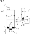
Während die Induktionsspule
Während des Betriebs, also während eines Energieübertragungsvorgangs, findet eine Kommunikation zwischen der Primärseite I und der Sekundärseite II statt. Diese Kommunikation wird durch eine Kommunikationseinrichtung
Der Gleichspannungswandler
Ist das Schaltelement
Gemäß dem Ausführungsbeispiel von
Claims (9)
Priority Applications (6)
| Application Number | Priority Date | Filing Date | Title |
|---|---|---|---|
| DE102011084485A DE102011084485A1 (en) | 2011-10-14 | 2011-10-14 | Device and method for the inductive transmission of electrical energy |
| RU2014119128A RU2623092C2 (en) | 2011-10-14 | 2012-08-27 | Device for inductive transmission of electric power and method for inductive transmission of electric power |
| CN201280049440.5A CN103858310B (en) | 2011-10-14 | 2012-08-27 | Equipment and method for vicarious transmission electric energy |
| US14/349,895 US9608474B2 (en) | 2011-10-14 | 2012-08-27 | Device and method for the inductive transmission of electrical energy |
| PCT/EP2012/066578 WO2013053530A2 (en) | 2011-10-14 | 2012-08-27 | Apparatus and method for inductively transmitting electrical energy |
| EP12756147.0A EP2766973B1 (en) | 2011-10-14 | 2012-08-27 | Apparatus and method for inductively transmitting electrical energy |
Applications Claiming Priority (1)
| Application Number | Priority Date | Filing Date | Title |
|---|---|---|---|
| DE102011084485A DE102011084485A1 (en) | 2011-10-14 | 2011-10-14 | Device and method for the inductive transmission of electrical energy |
Publications (1)
| Publication Number | Publication Date |
|---|---|
| DE102011084485A1 true DE102011084485A1 (en) | 2013-04-18 |
Family
ID=46801467
Family Applications (1)
| Application Number | Title | Priority Date | Filing Date |
|---|---|---|---|
| DE102011084485A Withdrawn DE102011084485A1 (en) | 2011-10-14 | 2011-10-14 | Device and method for the inductive transmission of electrical energy |
Country Status (6)
| Country | Link |
|---|---|
| US (1) | US9608474B2 (en) |
| EP (1) | EP2766973B1 (en) |
| CN (1) | CN103858310B (en) |
| DE (1) | DE102011084485A1 (en) |
| RU (1) | RU2623092C2 (en) |
| WO (1) | WO2013053530A2 (en) |
Cited By (3)
| Publication number | Priority date | Publication date | Assignee | Title |
|---|---|---|---|---|
| EP3258571A1 (en) * | 2016-06-15 | 2017-12-20 | Robert Bosch GmbH | Energy transfer system and method for operating an energy transfer system |
| US10299095B2 (en) | 2014-02-10 | 2019-05-21 | Intel Corporation | Wireless load modulation |
| DE102015100251B4 (en) | 2014-02-10 | 2023-12-21 | Intel Corporation | Wireless load modulation |
Families Citing this family (4)
| Publication number | Priority date | Publication date | Assignee | Title |
|---|---|---|---|---|
| US12495253B2 (en) | 2015-11-19 | 2025-12-09 | The Lovesac Company | Systems and methods for tuning based on furniture configuration |
| US11689856B2 (en) | 2015-11-19 | 2023-06-27 | The Lovesac Company | Electronic furniture systems with integrated induction charger |
| US12507009B2 (en) | 2015-11-19 | 2025-12-23 | The Lovesac Company | Systems and methods for correcting sound loss through partially acoustically transparent materials |
| US10212519B2 (en) | 2015-11-19 | 2019-02-19 | The Lovesac Company | Electronic furniture systems with integrated internal speakers |
Family Cites Families (6)
| Publication number | Priority date | Publication date | Assignee | Title |
|---|---|---|---|---|
| ES2166114T3 (en) * | 1998-03-03 | 2002-04-01 | Infineon Technologies Ag | DATA SUPPORT FOR THE NON-CONTACT RECEPTION OF SIGNALS MODULATED IN THE ENVIRONMENT. |
| WO2001031557A1 (en) * | 1999-10-22 | 2001-05-03 | Koninklijke Philips Electronics N.V. | Data carrier with load modulation means and with improved power supply in the process of load modulation |
| US20110050164A1 (en) | 2008-05-07 | 2011-03-03 | Afshin Partovi | System and methods for inductive charging, and improvements and uses thereof |
| WO2010035545A1 (en) * | 2008-09-26 | 2010-04-01 | 株式会社村田製作所 | Non-contact recharging system |
| JP4893755B2 (en) * | 2009-01-14 | 2012-03-07 | セイコーエプソン株式会社 | Power transmission control device, power transmission device, electronic device, and load state detection circuit |
| US9054385B2 (en) * | 2010-07-26 | 2015-06-09 | Energyor Technologies, Inc | Passive power management and battery charging for a hybrid fuel cell / battery system |
-
2011
- 2011-10-14 DE DE102011084485A patent/DE102011084485A1/en not_active Withdrawn
-
2012
- 2012-08-27 CN CN201280049440.5A patent/CN103858310B/en active Active
- 2012-08-27 US US14/349,895 patent/US9608474B2/en active Active
- 2012-08-27 WO PCT/EP2012/066578 patent/WO2013053530A2/en not_active Ceased
- 2012-08-27 EP EP12756147.0A patent/EP2766973B1/en active Active
- 2012-08-27 RU RU2014119128A patent/RU2623092C2/en active
Cited By (3)
| Publication number | Priority date | Publication date | Assignee | Title |
|---|---|---|---|---|
| US10299095B2 (en) | 2014-02-10 | 2019-05-21 | Intel Corporation | Wireless load modulation |
| DE102015100251B4 (en) | 2014-02-10 | 2023-12-21 | Intel Corporation | Wireless load modulation |
| EP3258571A1 (en) * | 2016-06-15 | 2017-12-20 | Robert Bosch GmbH | Energy transfer system and method for operating an energy transfer system |
Also Published As
| Publication number | Publication date |
|---|---|
| CN103858310A (en) | 2014-06-11 |
| EP2766973A2 (en) | 2014-08-20 |
| RU2623092C2 (en) | 2017-06-22 |
| CN103858310B (en) | 2016-10-26 |
| RU2014119128A (en) | 2015-11-20 |
| US20140354224A1 (en) | 2014-12-04 |
| EP2766973B1 (en) | 2021-02-24 |
| US9608474B2 (en) | 2017-03-28 |
| WO2013053530A3 (en) | 2013-06-20 |
| WO2013053530A2 (en) | 2013-04-18 |
Similar Documents
| Publication | Publication Date | Title |
|---|---|---|
| EP2766973B1 (en) | Apparatus and method for inductively transmitting electrical energy | |
| DE102016102417B4 (en) | Protection circuit for a photovoltaic (PV) module, method for operating the protection circuit and photovoltaic (PV) system with such a protection circuit | |
| EP3134952B1 (en) | Transmission system, method for inductively charging an electrically driven vehicle, and vehicle assembly | |
| DE102008021090A1 (en) | Circuit arrangement and method for exchanging electrical charge between accumulators of an accumulator arrangement | |
| DE102011118581A1 (en) | Contactless energy transfer system and control method therefor | |
| DE102013217816A1 (en) | Device for inductive energy transmission and method for operating a device for inductive energy transmission | |
| EP2289145A1 (en) | Regulation method for a high voltage dc transmission plant with dc link and self-commutated inverters | |
| WO2020043883A1 (en) | Method and device for the voltage matching of the smoothing capacitor of a dc-to-dc converter before a high-voltage battery is connected | |
| DE112013006090T5 (en) | Power transmission system | |
| EP3332466B1 (en) | Polarity reverser, inverter having reactive-power capability, and polarity reversing method | |
| DE102019004440A1 (en) | Circuit power converters and methods and circuits for their control | |
| DE102015214236A1 (en) | Method and device for operating a DC-DC converter, electrical system | |
| DE102013209383A1 (en) | Battery with at least one battery string with several battery modules and method for controlling a battery voltage | |
| DE102014203716A1 (en) | Device and method for driving a DC-DC converter | |
| DE102013109608A1 (en) | Method and feed-in control for feeding electrical power into a line branch | |
| EP3695500B1 (en) | Intermediate circuit converter with targeted coupling with at least one other intermediate circuit converter | |
| EP3303935B1 (en) | Device and method for controlling a heating and/or cooling system | |
| DE102019212887A1 (en) | Control method for a DC voltage converter and DC voltage converter | |
| DE102012218596B4 (en) | Control unit for an on-board network, on-board network and method for operating an on-board network | |
| DE102014015857A1 (en) | Circuit device for charging a capacitor | |
| WO2024041779A1 (en) | Method for operating a flyback converter for charging a dc link capacitor | |
| DE102009048587A1 (en) | Device for use in energy storage system for controlling charging current in lithium-ion-battery, has control unit for controlling switching elements, so that bypass current is guided to battery in one of switching conditions | |
| EP4529699A1 (en) | Method for increasing the service life of converter switches, and system | |
| DE102015113071B4 (en) | Potential-shifting half-bridge, pole-reverser and reactive power inverters as well as Polwendeverfahren | |
| DE102012210207A1 (en) | Method and device for feeding electrical power into an electrical power grid |
Legal Events
| Date | Code | Title | Description |
|---|---|---|---|
| R079 | Amendment of ipc main class |
Free format text: PREVIOUS MAIN CLASS: H02J0017000000 Ipc: H02J0050100000 |
|
| R012 | Request for examination validly filed | ||
| R119 | Application deemed withdrawn, or ip right lapsed, due to non-payment of renewal fee |