DE102011080848A1 - Electric compartment exhaust duct with improved air cooling - Google Patents
Electric compartment exhaust duct with improved air cooling Download PDFInfo
- Publication number
- DE102011080848A1 DE102011080848A1 DE102011080848A DE102011080848A DE102011080848A1 DE 102011080848 A1 DE102011080848 A1 DE 102011080848A1 DE 102011080848 A DE102011080848 A DE 102011080848A DE 102011080848 A DE102011080848 A DE 102011080848A DE 102011080848 A1 DE102011080848 A1 DE 102011080848A1
- Authority
- DE
- Germany
- Prior art keywords
- air
- compartment
- exhaust
- duct
- exhaust air
- Prior art date
- Legal status (The legal status is an assumption and is not a legal conclusion. Google has not performed a legal analysis and makes no representation as to the accuracy of the status listed.)
- Withdrawn
Links
Images

Classifications
-
- B—PERFORMING OPERATIONS; TRANSPORTING
- B60—VEHICLES IN GENERAL
- B60H—ARRANGEMENTS OF HEATING, COOLING, VENTILATING OR OTHER AIR-TREATING DEVICES SPECIALLY ADAPTED FOR PASSENGER OR GOODS SPACES OF VEHICLES
- B60H1/00—Heating, cooling or ventilating devices
- B60H1/00271—HVAC devices specially adapted for particular vehicle parts or components and being connected to the vehicle HVAC unit
- B60H1/00278—HVAC devices specially adapted for particular vehicle parts or components and being connected to the vehicle HVAC unit for the battery
-
- B—PERFORMING OPERATIONS; TRANSPORTING
- B60—VEHICLES IN GENERAL
- B60H—ARRANGEMENTS OF HEATING, COOLING, VENTILATING OR OTHER AIR-TREATING DEVICES SPECIALLY ADAPTED FOR PASSENGER OR GOODS SPACES OF VEHICLES
- B60H1/00—Heating, cooling or ventilating devices
- B60H1/00507—Details, e.g. mounting arrangements, desaeration devices
- B60H1/00557—Details of ducts or cables
- B60H1/00564—Details of ducts or cables of air ducts
-
- B—PERFORMING OPERATIONS; TRANSPORTING
- B60—VEHICLES IN GENERAL
- B60H—ARRANGEMENTS OF HEATING, COOLING, VENTILATING OR OTHER AIR-TREATING DEVICES SPECIALLY ADAPTED FOR PASSENGER OR GOODS SPACES OF VEHICLES
- B60H1/00—Heating, cooling or ventilating devices
- B60H1/00271—HVAC devices specially adapted for particular vehicle parts or components and being connected to the vehicle HVAC unit
- B60H2001/003—Component temperature regulation using an air flow
Landscapes
- Physics & Mathematics (AREA)
- Thermal Sciences (AREA)
- Engineering & Computer Science (AREA)
- Mechanical Engineering (AREA)
- Cooling, Air Intake And Gas Exhaust, And Fuel Tank Arrangements In Propulsion Units (AREA)
- Electric Propulsion And Braking For Vehicles (AREA)
- Air-Conditioning For Vehicles (AREA)
Abstract
Zum Kühlen von elektrischer Ausrüstung in einem Elektrokraftfahrzeug erstreckt sich ein Abluftkanal, der Abluft befördert, die aus einem Elektrikfach strömt, das hinter und/oder unter einem Sitz angeordnet ist, unter dem Sitz und lüftet in die Fahrgastzelle ab. Der Abluftkanal weist stromabwärts von dem Elektrikfach mindestens eine Luftansaugöffnung auf, um Hilfskühlluft aus der Fahrgastzelle in den Kanal zu saugen und sie mit der Abluft zu vereinigen. Beim Hindurchtreten von Abluft aus dem Elektrikfach durch den Abluftkanal wird Hilfskühlluft durch die Luftansaugöffnungen in den Abluftkanal gesaugt und mit der wärmeren Luft aus dem Fach vermischt, um die Temperatur des Luftgemisches, das aus dem Abluftkanal austritt, zu senken. In dem Abluftkanal können Vorrichtungen zur Luftvermischung angeordnet sein, um das Vermischen des Luftstroms aus dem Elektrikfach mit der Hilfskühlluft zu verbessern.To cool electrical equipment in an electric motor vehicle, an exhaust air duct that conveys exhaust air that flows from an electrical compartment that is arranged behind and / or under a seat extends under the seat and ventilates into the passenger compartment. The exhaust air duct has at least one air intake opening downstream of the electrical compartment in order to draw auxiliary cooling air from the passenger compartment into the duct and to combine it with the exhaust air. When exhaust air from the electrical compartment passes through the exhaust air duct, auxiliary cooling air is drawn in through the air intake openings into the exhaust air duct and mixed with the warmer air from the compartment in order to lower the temperature of the air mixture that emerges from the exhaust air duct. Devices for air mixing can be arranged in the exhaust air duct in order to improve the mixing of the air flow from the electrical compartment with the auxiliary cooling air.
Description
HINTERGRUNDBACKGROUND
1. Technisches Gebiet1. Technical area
Die vorliegende Erfindung betrifft elektrisch angetriebene Kraftfahrzeuge mit luftgekühlten elektrischen Bauteilen.The present invention relates to electrically powered vehicles having air cooled electrical components.
2. Stand der Technik2. State of the art
Elektrisch angetriebene Fahrzeuge, wie z. B. Hybridelektrokraftfahrzeuge (HEV), Plug-in-HEV, rein elektrische Fahrzeuge usw., umfassen im Allgemeinen elektrische Bauteile (Batterien, Batterieladegeräte, Wandler (Gleichstrom/Gleichstrom, Wechselstrom/Gleichstrom und/oder Gleichstrom/Wechselstrom) und/oder Umrichter), die während des Betriebs ein gewisses Maß an Abwärme erzeugen. Solche elektrischen Bauteile, insbesondere Hochspannungsbauteile, können ein beträchtliches Maß an Abwärme erzeugen und daher einen gewissen Grad an aktiver Kühlung benötigen. Dieses Kühlen kann durch Bereitstellen eines verhältnismäßig konstanten Luftstroms aus der Fahrgastzelle, dem Gepäckraum und/oder von der Außenseite des Fahrzeugs in das Elektrikfach erreicht werden.Electrically powered vehicles, such as. As hybrid electric vehicles (HEV), plug-in HEV, purely electric vehicles, etc., generally include electrical components (batteries, battery chargers, converters (DC / DC, AC / DC and / or DC / AC) and / or inverter) which generate a certain amount of waste heat during operation. Such electrical components, particularly high voltage components, can generate a significant amount of waste heat and therefore require some degree of active cooling. This cooling can be achieved by providing a relatively constant flow of air from the passenger compartment, the luggage compartment and / or from the outside of the vehicle into the electrical compartment.
Bei einer herkömmlichen Fahrzeugausgestaltung befindet sich ein Fach, das elektrische Bauteile enthält, unmittelbar hinter und/oder unter einer oder mehreren Insassensitzpositionen. Kühlluft wird von einem Ventilator durch das Elektrikfach gedrückt oder gesaugt, und die warme Abluft wird durch einen Abluftkanal, der sich unter dem Rücksitz erstreckt, in den Fahrgastraum und/oder Gepäckraum ausgestoßen.In a conventional vehicle design, a compartment containing electrical components is located immediately behind and / or under one or more occupant seating positions. Cooling air is forced or sucked by a fan through the electrical compartment, and the warm exhaust air is expelled through an exhaust duct extending under the rear seat into the passenger compartment and / or luggage compartment.
Unter bestimmten Bedingungen kann die Kühlluft, die aus dem Abgaskanal aus- und in den Fahrgastraum eintritt, so warm sein, dass sie die Temperatur im Sitzbereich auf ein unangenehmes Maß erhöht.Under certain conditions, the cooling air exiting the exhaust passageway and entering the passenger compartment may be so warm that it raises the temperature in the seating area to an uncomfortable level.
KURZFASSUNGSHORT VERSION
Gemäß einer Ausführungsform der Offenbarung umfasst ein Kühlsystem für elektrische Ausrüstung, die in einem Elektrikfach untergebracht ist, das hinter und/oder unter einem Sitz eines Kraftfahrzeugs nach vorne gerichtet angeordnet ist, einen Abluftkanal, der Abluft befördert, die aus dem Elektrikfach strömt, und der sich unter dem Sitz erstreckt und diese in die Fahrgastzelle ablüftet. Der Abluftkanal weist stromabwärts von dem Elektrikfach mindestens eine Luftansaugöffnung auf und saugt Kühlluft aus der Fahrgastzelle in den Kanal ein, um sie mit der Abluft zu vereinigen. Beim Hindurchtreten von Abluft aus dem Elektrikfach durch den Abluftkanal wird Hilfskühlluft durch die Luftansaugöffnungen in den Abluftkanal gesaugt und mit der wärmeren Luft aus dem Fach vermischt, um die Temperatur des Luftgemisches, das aus dem Abluftkanal austritt, zu senken. Innerhalb des Abluftkanals können Vorrichtungen zur Luftvermischung angeordnet sein, um das Vermischen des Luftstromes aus dem Elektrikfach mit der Hilfskühlluft zu verbessern.According to an embodiment of the disclosure, an electric equipment cooling system accommodated in an electric compartment arranged forwardly behind and / or under a seat of an automobile includes an exhaust duct conveying exhaust air flowing out of the electric compartment, and extends under the seat and vented into the passenger compartment. The exhaust duct has downstream of the electrical compartment at least one air intake opening and sucks cooling air from the passenger compartment in the channel to unite them with the exhaust air. When passage of exhaust air from the electrical compartment through the exhaust duct, auxiliary cooling air is drawn through the air intake openings into the exhaust duct and mixed with the warmer air from the compartment to lower the temperature of the air mixture exiting the exhaust duct. Within the exhaust duct, air mixing devices may be arranged to enhance the mixing of the airflow from the electrical compartment with the auxiliary cooling air.
KURZBESCHREIBUNG DER ZEICHNUNGENBRIEF DESCRIPTION OF THE DRAWINGS
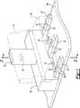
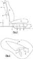
Ausführungsformen der vorliegenden Erfindung werden nun anhand von bloßen Beispielen mit Bezug auf die beigefügten Zeichnungen beschrieben, wobeiEmbodiments of the present invention will now be described by way of example only with reference to the accompanying drawings, in which: FIG
AUSFÜHRLICHE BESCHREIBUNGDETAILED DESCRIPTION
Wie vorgeschrieben, sind hierin Ausführungsformen der vorliegenden Erfindung in Einzelheiten offenbart; es versteht sich jedoch, dass die offenbarten Ausführungsformen bloße Beispiele für die Erfindung sind, die in verschiedenen und alternativen Ausführungsformen ausgestaltet werden kann. Die Figuren sind nicht unbedingt maßstabgetreu; einige Merkmale können übertrieben groß oder verkleinert sein, um Einzelheiten bestimmter Bauteile zu zeigen. Daher sollten hierin offenbarte spezifische strukturelle und funktionale Einzelheiten nicht als einschränkend, sondern lediglich als eine darstellende Grundlage zur Unterrichtung der Fachperson, die vorliegende Erfindung in verschiedenartiger Weise anzuwenden, ausgelegt werden.As prescribed, embodiments of the present invention are disclosed in detail herein; however, it should be understood that the disclosed embodiments are merely examples of the invention that may be embodied in various and alternative embodiments. The figures are not necessarily to scale; some features may be exaggerated or oversized to show details of particular components. Therefore, specific structural and functional details disclosed herein should not be construed as limiting, but merely as an illustrative basis for teaching one skilled in the art to variously employ the present invention.
Es wird auf
Ein oder mehrere Abluftkanäle
Abluftkanäle
Öffnungen oder Tunnel
In
Beim Strömen von Abluft aus dem Elektrikfach
Obschon oben beispielhafte Ausführungsformen beschrieben sind, ist nicht beabsichtigt, mit diesen Ausführungsformen alle möglichen Ausformungen der Erfindung zu beschreiben. Die in der Beschreibung benutzten Wörter sind beschreibende und keine einschränkenden Wörter, und es versteht sich, dass verschiedene Änderungen vorgenommen werden können, ohne von dem Sinn und dem Umfang der Erfindung abzurücken. Außerdem können die Merkmale verschiedener umsetzender Ausführungsformen kombiniert werden, um weitere Ausführungsformen der Erfindung zu bilden.Although exemplary embodiments are described above, it is not intended that these embodiments describe all possible forms of the invention. The words used in the description are words of description rather than limitation, and it is understood that various changes may be made without departing from the spirit and scope of the invention. In addition, the features of various implementing embodiments may be combined to form further embodiments of the invention.
Claims (6)
Applications Claiming Priority (2)
| Application Number | Priority Date | Filing Date | Title |
|---|---|---|---|
| US12/862,824 | 2010-08-25 | ||
| US12/862,824 US20110165832A1 (en) | 2010-08-25 | 2010-08-25 | Electric compartment exhaust duct with enhanced air cooling features |
Publications (1)
| Publication Number | Publication Date |
|---|---|
| DE102011080848A1 true DE102011080848A1 (en) | 2012-03-01 |
Family
ID=44224967
Family Applications (1)
| Application Number | Title | Priority Date | Filing Date |
|---|---|---|---|
| DE102011080848A Withdrawn DE102011080848A1 (en) | 2010-08-25 | 2011-08-11 | Electric compartment exhaust duct with improved air cooling |
Country Status (3)
| Country | Link |
|---|---|
| US (1) | US20110165832A1 (en) |
| CN (1) | CN102381154B (en) |
| DE (1) | DE102011080848A1 (en) |
Cited By (1)
| Publication number | Priority date | Publication date | Assignee | Title |
|---|---|---|---|---|
| DE102014209323A1 (en) * | 2014-05-16 | 2015-11-19 | Mahle International Gmbh | Plastic component |
Families Citing this family (5)
| Publication number | Priority date | Publication date | Assignee | Title |
|---|---|---|---|---|
| DE102012204892A1 (en) * | 2012-03-27 | 2013-10-02 | Mekra Lang Gmbh & Co. Kg | Temperable housing for receiving an electronic device and vehicle with this housing |
| US12292192B2 (en) * | 2019-08-09 | 2025-05-06 | Rlh Industries, Inc. | Intake device for a chimney termination |
| DE102020210454A1 (en) | 2019-08-27 | 2021-05-12 | Motional AD LLC (n.d.Ges.d. Staates Delaware) | Cooling solutions for autonomous vehicles |
| DE102020121532A1 (en) | 2019-08-29 | 2021-03-04 | Motional AD LLC (n.d.Ges.d. Staates Delaware) | Sensor housing |
| WO2026047826A1 (en) * | 2024-08-26 | 2026-03-05 | 日産自動車株式会社 | Exhaust structure of fan for cooling battery |
Family Cites Families (59)
| Publication number | Priority date | Publication date | Assignee | Title |
|---|---|---|---|---|
| US2989854A (en) * | 1960-03-28 | 1961-06-27 | Gen Motors Corp | Vehicle refrigeration |
| US3908900A (en) * | 1974-04-29 | 1975-09-30 | James R Smith | Recirculating automotive heating system |
| ZA771500B (en) * | 1977-03-11 | 1978-06-28 | Ventline Mfg Ltd | Improvements in or relating to air conditioning |
| US5127878A (en) * | 1980-09-05 | 1992-07-07 | Camp Dresser & Mckee | Mixing box |
| US4616559A (en) * | 1985-05-20 | 1986-10-14 | Pure Air Inc. | Variable air diffuser |
| DE4001148A1 (en) * | 1990-01-17 | 1991-07-18 | Deere & Co | Feeding external air into tractor cabin via conduits - incorporating filter elements readily accessible from exterior |
| US5392873A (en) * | 1992-01-22 | 1995-02-28 | Honda Giken Kogyo Kabushiki Kaisha | Structure for securing batteries used in an electric vehicle |
| JP3044975B2 (en) * | 1992-12-10 | 2000-05-22 | トヨタ自動車株式会社 | Battery heating device for electric vehicles |
| DE4304076C2 (en) * | 1993-02-11 | 1996-03-07 | Behr Gmbh & Co | Method and device for heating the passenger compartment of a motor vehicle |
| US5354114A (en) * | 1993-06-21 | 1994-10-11 | Davidson Textron Inc. | Integrated cross car structural duct cluster |
| DE4433836C1 (en) * | 1994-09-22 | 1995-11-09 | Daimler Benz Ag | Device for heating an interior of an electric vehicle |
| CA2151773C (en) * | 1995-06-14 | 2000-03-28 | Vernon Casper Badry | Air inductor device for controlled fresh air intake in an air heating system |
| US5706170A (en) * | 1996-05-03 | 1998-01-06 | Ford Motor Company | Ventilation duct with integrated electronics enclosure |
| JP3240973B2 (en) * | 1997-03-05 | 2001-12-25 | トヨタ自動車株式会社 | Battery cooling system for vehicles |
| JP3509517B2 (en) * | 1997-12-18 | 2004-03-22 | 本田技研工業株式会社 | Cooling structure of battery and electric parts in electric vehicle |
| FR2775221B1 (en) * | 1998-02-20 | 2000-05-26 | Renault | VENTILATION, HEATING AND AIR CONDITIONING DEVICE FOR A PASSENGER COMPARTMENT OF A MOTOR VEHICLE |
| DE19908497C2 (en) * | 1999-02-26 | 2003-03-13 | Daimler Chrysler Ag | Open vehicle |
| US6383599B1 (en) * | 1999-03-04 | 2002-05-07 | Daimlerchrysler Corporation | Carpet with integrated ventilation duct and footrest and method for making same |
| US6394210B2 (en) * | 1999-06-07 | 2002-05-28 | Mitsubishi Heavy Industries, Ltd. | Temperature controller for vehicular battery |
| JP4224939B2 (en) * | 2000-03-31 | 2009-02-18 | 株式会社デンソー | Air conditioner for vehicles |
| JP3777981B2 (en) * | 2000-04-13 | 2006-05-24 | トヨタ自動車株式会社 | Vehicle power supply |
| US6361429B1 (en) * | 2001-05-07 | 2002-03-26 | Delphi Technologies, Inc. | Reduced noise automotive ventilation system |
| US6409591B1 (en) * | 2001-06-05 | 2002-06-25 | Daimlerchrysler Corporation | Automotive vehicle exhauster vent |
| JP2004026008A (en) * | 2002-06-25 | 2004-01-29 | Honda Motor Co Ltd | Fuel cell electric vehicle |
| US6902020B2 (en) * | 2002-07-29 | 2005-06-07 | Daimlerchrysler Corporation | Interior vehicle battery system and method |
| US6612923B1 (en) * | 2002-09-23 | 2003-09-02 | Brian M Flynn | Warm tube mixing box |
| US7048321B2 (en) * | 2003-05-21 | 2006-05-23 | Honda Motor Co., Ltd. | High-voltage electrical equipment case arranging structure |
| US6857955B1 (en) * | 2003-06-04 | 2005-02-22 | Steven M Held | Ventilation extension kit |
| JP4519516B2 (en) * | 2003-07-15 | 2010-08-04 | 本田技研工業株式会社 | Heating / cooling device for vehicle electrical unit and hybrid vehicle |
| US6899366B2 (en) * | 2003-10-23 | 2005-05-31 | Daimlerchrysler Corporation | Vehicle storage and ventilation system |
| JP3784813B2 (en) * | 2003-11-26 | 2006-06-14 | 本田技研工業株式会社 | High-voltage cooling device for vehicle motor and hybrid vehicle |
| JP4042694B2 (en) * | 2003-12-26 | 2008-02-06 | トヨタ自動車株式会社 | Cooling device for power storage mechanism |
| US6899381B1 (en) * | 2003-12-30 | 2005-05-31 | Lear Corporation | Vehicle headliner with a flexible duct |
| JP2005254974A (en) * | 2004-03-11 | 2005-09-22 | Toyota Motor Corp | Vehicle temperature control system |
| US7290829B2 (en) * | 2004-06-29 | 2007-11-06 | Kubota Corporation | Working vehicle with a cab |
| FR2874552B1 (en) * | 2004-08-27 | 2006-10-06 | Valeo Climatisation Sa | DEVICE FOR JOINING AN AERATION DUCT EQUIPPING THE SEAT OF A TILTING AND / OR REMOVABLE SEAT, IN PARTICULAR A VEHICLE, AND A CONDUIT OF AIR SUPPLY. |
| EP2071647B1 (en) * | 2004-10-08 | 2018-01-17 | Honda Motor Co., Ltd. | Interlock structure of electric component box |
| KR20060106507A (en) * | 2005-04-09 | 2006-10-12 | 한라공조주식회사 | Car seat air conditioner |
| CN100508273C (en) * | 2005-06-02 | 2009-07-01 | 本田技研工业株式会社 | Power supply device for vehicle and cooling structure for battery |
| JP4415910B2 (en) * | 2005-07-12 | 2010-02-17 | トヨタ自動車株式会社 | Hybrid vehicle structure |
| JP4673692B2 (en) * | 2005-07-19 | 2011-04-20 | 本田技研工業株式会社 | Cooling structure for electrical equipment in vehicles |
| JP2007091195A (en) * | 2005-08-31 | 2007-04-12 | Honda Motor Co Ltd | Motorcycle wiring / piping support equipment |
| JP4297105B2 (en) * | 2005-10-14 | 2009-07-15 | トヨタ自動車株式会社 | Storage device cooling structure |
| US7552545B2 (en) * | 2005-10-25 | 2009-06-30 | Maytag Corporation | Ducted drying rack for clothes dryer |
| US7396062B2 (en) * | 2006-03-01 | 2008-07-08 | Visteon Global Technologies, Inc. | Structural pedestal conduit for air handling and electrical routing |
| JP4940749B2 (en) * | 2006-04-28 | 2012-05-30 | トヨタ自動車株式会社 | Power supply device mounting structure |
| DE602007010216D1 (en) * | 2006-09-07 | 2010-12-16 | Honda Motor Co Ltd | Cooling structure of an electrical device in a vehicle |
| US7364224B2 (en) * | 2006-09-29 | 2008-04-29 | Nissan Technical Center North America, Inc. | Combination harness protector and carpet |
| US7988543B2 (en) * | 2006-12-12 | 2011-08-02 | GM Global Technology Operations LLC | Battery pack and HVAC air handling and controls |
| US7419209B1 (en) * | 2007-05-30 | 2008-09-02 | Lear Corporation | Seat assembly providing airflow path to cool batteries |
| US20080297136A1 (en) * | 2007-05-30 | 2008-12-04 | Ford Global Technologies, Llc | System and method to detect, in a vehicle, blockage of an airflow passage to a power storage unit |
| US20090042501A1 (en) * | 2007-08-07 | 2009-02-12 | Hung Stephen T | Localized Air Distribution System |
| JP4957492B2 (en) * | 2007-09-28 | 2012-06-20 | 三菱自動車工業株式会社 | Electric vehicle battery unit cooling duct structure |
| US8029343B2 (en) * | 2007-10-02 | 2011-10-04 | Gm Global Technology Operations, Llc | Vehicle body pressure relief system |
| KR100917374B1 (en) * | 2007-12-11 | 2009-09-16 | 조병남 | High rise building ventilation system using exterior curtain wall as exhaust space |
| JP5058142B2 (en) * | 2008-12-19 | 2012-10-24 | 本田技研工業株式会社 | Vehicle wiring structure |
| SE533440C2 (en) * | 2009-01-26 | 2010-09-28 | Swegon Ab | Induction apparatus for combining air flows |
| JP5531626B2 (en) * | 2009-05-26 | 2014-06-25 | 日産自動車株式会社 | Vehicle battery assembly cooling structure and battery assembly with water jacket |
| US8118354B2 (en) * | 2010-05-12 | 2012-02-21 | Ford Global Technologies, Llc | Collapsible under-seat exhaust duct for battery compartment |
-
2010
- 2010-08-25 US US12/862,824 patent/US20110165832A1/en not_active Abandoned
-
2011
- 2011-08-11 DE DE102011080848A patent/DE102011080848A1/en not_active Withdrawn
- 2011-08-12 CN CN201110230971.1A patent/CN102381154B/en not_active Expired - Fee Related
Cited By (1)
| Publication number | Priority date | Publication date | Assignee | Title |
|---|---|---|---|---|
| DE102014209323A1 (en) * | 2014-05-16 | 2015-11-19 | Mahle International Gmbh | Plastic component |
Also Published As
| Publication number | Publication date |
|---|---|
| CN102381154B (en) | 2016-01-27 |
| US20110165832A1 (en) | 2011-07-07 |
| CN102381154A (en) | 2012-03-21 |
Similar Documents
| Publication | Publication Date | Title |
|---|---|---|
| DE112011101671B4 (en) | Vehicle battery cooling device | |
| DE102011089301B4 (en) | High-voltage barrier kit assembly for a vehicle | |
| DE102014108303B4 (en) | Air conditioning device for a vehicle | |
| DE102014004303B4 (en) | Vehicle Battery Pack Device | |
| DE102008049490B4 (en) | Body pressure relief system for a motor vehicle | |
| DE102013223667B4 (en) | Battery pack cooling structure for a motor vehicle | |
| DE102013206786B4 (en) | ARMREST FOR VEHICLE | |
| DE102011080848A1 (en) | Electric compartment exhaust duct with improved air cooling | |
| DE102011077339A1 (en) | Device and method for electric room cooling | |
| DE102015223373A1 (en) | AIR FLOW GUIDANCE SYSTEM FOR VEHICLES | |
| DE102011085945A1 (en) | Cooling arrangement for an environmentally friendly vehicle | |
| DE102011002983A1 (en) | Vehicle seat with air duct | |
| DE102014216698A1 (en) | COOL AIR COLLECTORS FOR A HIGH VOLTAGE BATTERY | |
| DE102007059447A1 (en) | Air steering and controls for battery pack and HVAC | |
| DE102015222891B4 (en) | Seat with heating device | |
| DE4425871A1 (en) | Air conditioning method in an aircraft and device for carrying out the method | |
| DE102014100216A1 (en) | REAR VENTILATION CHANNELS FOR VEHICLES | |
| DE102016218204A1 (en) | Vehicle air conditioning | |
| DE102016200600B4 (en) | Cooling mechanism for a battery pack for use in vehicles | |
| DE102014117887A1 (en) | Air conditioning system for vehicle | |
| DE102015110896B4 (en) | Noise-insulating snorkel channel for recirculation opening of a vehicle ventilation system | |
| DE102016216367A1 (en) | COOLING MECHANISM FOR A BATTERY PACK FOR A VEHICLE | |
| DE102013206783A1 (en) | ARMREST FOR VEHICLE | |
| DE102016117443A1 (en) | Seat with a ventilation device and method for air conditioning the seating environment | |
| DE102011089279A1 (en) | System and apparatus for cooling high voltage components of a vehicle |
Legal Events
| Date | Code | Title | Description |
|---|---|---|---|
| R082 | Change of representative |
Representative=s name: NEIDL-STIPPLER, CORNELIA, DIPL.-CHEM.DR.PHIL.N, DE Representative=s name: CORNELIA NEIDL-STIPPLER, DE Representative=s name: CORNELIA NEIDL-STIPPLER, 81679 MUENCHEN, DE |
|
| R012 | Request for examination validly filed | ||
| R012 | Request for examination validly filed | ||
| R005 | Application deemed withdrawn due to failure to request examination | ||
| R079 | Amendment of ipc main class |
Free format text: PREVIOUS MAIN CLASS: B60K0001000000 Ipc: B60H0001000000 |
|
| R073 | Re-establishment requested | ||
| R074 | Re-establishment allowed | ||
| R074 | Re-establishment allowed | ||
| R119 | Application deemed withdrawn, or ip right lapsed, due to non-payment of renewal fee |