DE102011052145A1 - CANISTER FOR VEHICLES AND FUEL EVAPORATION SYSTEM WITH THIS - Google Patents
CANISTER FOR VEHICLES AND FUEL EVAPORATION SYSTEM WITH THIS Download PDFInfo
- Publication number
- DE102011052145A1 DE102011052145A1 DE201110052145 DE102011052145A DE102011052145A1 DE 102011052145 A1 DE102011052145 A1 DE 102011052145A1 DE 201110052145 DE201110052145 DE 201110052145 DE 102011052145 A DE102011052145 A DE 102011052145A DE 102011052145 A1 DE102011052145 A1 DE 102011052145A1
- Authority
- DE
- Germany
- Prior art keywords
- air
- canister
- fuel
- ptc
- air duct
- Prior art date
- Legal status (The legal status is an assumption and is not a legal conclusion. Google has not performed a legal analysis and makes no representation as to the accuracy of the status listed.)
- Withdrawn
Links
- 238000001704 evaporation Methods 0.000 title claims abstract description 65
- 230000008020 evaporation Effects 0.000 title claims abstract description 61
- 239000000446 fuel Substances 0.000 title claims description 52
- 239000003570 air Substances 0.000 claims abstract description 141
- OKTJSMMVPCPJKN-UHFFFAOYSA-N Carbon Chemical compound [C] OKTJSMMVPCPJKN-UHFFFAOYSA-N 0.000 claims abstract description 48
- 238000010438 heat treatment Methods 0.000 claims abstract description 38
- 239000002828 fuel tank Substances 0.000 claims abstract description 23
- 238000002485 combustion reaction Methods 0.000 claims abstract description 19
- 239000012080 ambient air Substances 0.000 claims abstract description 5
- 239000007789 gas Substances 0.000 claims description 66
- 239000012212 insulator Substances 0.000 claims description 8
- 239000000853 adhesive Substances 0.000 claims description 6
- 230000001070 adhesive effect Effects 0.000 claims description 6
- 238000013022 venting Methods 0.000 claims description 6
- 230000005611 electricity Effects 0.000 claims description 4
- 238000009423 ventilation Methods 0.000 abstract description 7
- 238000010521 absorption reaction Methods 0.000 description 9
- 238000006243 chemical reaction Methods 0.000 description 6
- 239000000126 substance Substances 0.000 description 5
- 229930195733 hydrocarbon Natural products 0.000 description 4
- 150000002430 hydrocarbons Chemical class 0.000 description 4
- 230000008901 benefit Effects 0.000 description 3
- 238000012986 modification Methods 0.000 description 3
- 230000004048 modification Effects 0.000 description 3
- CLODVDBWNVQLGO-UHFFFAOYSA-N 1,2,4,5-tetrachloro-3-(2,6-dichlorophenyl)benzene Chemical compound ClC1=CC=CC(Cl)=C1C1=C(Cl)C(Cl)=CC(Cl)=C1Cl CLODVDBWNVQLGO-UHFFFAOYSA-N 0.000 description 2
- 239000002250 absorbent Substances 0.000 description 2
- 230000002745 absorbent Effects 0.000 description 2
- 239000002156 adsorbate Substances 0.000 description 2
- 230000000740 bleeding effect Effects 0.000 description 2
- 230000003247 decreasing effect Effects 0.000 description 2
- 238000000034 method Methods 0.000 description 2
- BUHVIAUBTBOHAG-FOYDDCNASA-N (2r,3r,4s,5r)-2-[6-[[2-(3,5-dimethoxyphenyl)-2-(2-methylphenyl)ethyl]amino]purin-9-yl]-5-(hydroxymethyl)oxolane-3,4-diol Chemical compound COC1=CC(OC)=CC(C(CNC=2C=3N=CN(C=3N=CN=2)[C@H]2[C@@H]([C@H](O)[C@@H](CO)O2)O)C=2C(=CC=CC=2)C)=C1 BUHVIAUBTBOHAG-FOYDDCNASA-N 0.000 description 1
- 238000005411 Van der Waals force Methods 0.000 description 1
- 230000033228 biological regulation Effects 0.000 description 1
- 235000013844 butane Nutrition 0.000 description 1
- 239000000470 constituent Substances 0.000 description 1
- 230000008878 coupling Effects 0.000 description 1
- 238000010168 coupling process Methods 0.000 description 1
- 238000005859 coupling reaction Methods 0.000 description 1
- 230000007423 decrease Effects 0.000 description 1
- 230000002950 deficient Effects 0.000 description 1
- 238000009792 diffusion process Methods 0.000 description 1
- 238000007599 discharging Methods 0.000 description 1
- 238000005516 engineering process Methods 0.000 description 1
- 239000003344 environmental pollutant Substances 0.000 description 1
- 230000002427 irreversible effect Effects 0.000 description 1
- 238000002955 isolation Methods 0.000 description 1
- 230000007257 malfunction Effects 0.000 description 1
- 239000000463 material Substances 0.000 description 1
- 239000000203 mixture Substances 0.000 description 1
- IJDNQMDRQITEOD-UHFFFAOYSA-N n-butane Chemical class CCCC IJDNQMDRQITEOD-UHFFFAOYSA-N 0.000 description 1
- 231100000719 pollutant Toxicity 0.000 description 1
- 229920001296 polysiloxane Polymers 0.000 description 1
- 230000027756 respiratory electron transport chain Effects 0.000 description 1
- 230000002441 reversible effect Effects 0.000 description 1
Images


Classifications
-
- F—MECHANICAL ENGINEERING; LIGHTING; HEATING; WEAPONS; BLASTING
- F02—COMBUSTION ENGINES; HOT-GAS OR COMBUSTION-PRODUCT ENGINE PLANTS
- F02M—SUPPLYING COMBUSTION ENGINES IN GENERAL WITH COMBUSTIBLE MIXTURES OR CONSTITUENTS THEREOF
- F02M25/00—Engine-pertinent apparatus for adding non-fuel substances or small quantities of secondary fuel to combustion-air, main fuel or fuel-air mixture
- F02M25/08—Engine-pertinent apparatus for adding non-fuel substances or small quantities of secondary fuel to combustion-air, main fuel or fuel-air mixture adding fuel vapours drawn from engine fuel reservoir
- F02M25/0854—Details of the absorption canister
-
- F—MECHANICAL ENGINEERING; LIGHTING; HEATING; WEAPONS; BLASTING
- F02—COMBUSTION ENGINES; HOT-GAS OR COMBUSTION-PRODUCT ENGINE PLANTS
- F02M—SUPPLYING COMBUSTION ENGINES IN GENERAL WITH COMBUSTIBLE MIXTURES OR CONSTITUENTS THEREOF
- F02M25/00—Engine-pertinent apparatus for adding non-fuel substances or small quantities of secondary fuel to combustion-air, main fuel or fuel-air mixture
- F02M25/08—Engine-pertinent apparatus for adding non-fuel substances or small quantities of secondary fuel to combustion-air, main fuel or fuel-air mixture adding fuel vapours drawn from engine fuel reservoir
-
- F—MECHANICAL ENGINEERING; LIGHTING; HEATING; WEAPONS; BLASTING
- F02—COMBUSTION ENGINES; HOT-GAS OR COMBUSTION-PRODUCT ENGINE PLANTS
- F02M—SUPPLYING COMBUSTION ENGINES IN GENERAL WITH COMBUSTIBLE MIXTURES OR CONSTITUENTS THEREOF
- F02M33/00—Other apparatus for treating combustion-air, fuel or fuel-air mixture
- F02M33/02—Other apparatus for treating combustion-air, fuel or fuel-air mixture for collecting and returning condensed fuel
- F02M33/04—Other apparatus for treating combustion-air, fuel or fuel-air mixture for collecting and returning condensed fuel returning to the intake passage
- F02M33/06—Other apparatus for treating combustion-air, fuel or fuel-air mixture for collecting and returning condensed fuel returning to the intake passage with simultaneous heat supply
Landscapes
- Engineering & Computer Science (AREA)
- Chemical & Material Sciences (AREA)
- Combustion & Propulsion (AREA)
- Mechanical Engineering (AREA)
- General Engineering & Computer Science (AREA)
- Supplying Secondary Fuel Or The Like To Fuel, Air Or Fuel-Air Mixtures (AREA)
- Separation Of Gases By Adsorption (AREA)
Abstract
Ein Kanister (30) für ein Kraftfahrzeug ist mit darin angeordneter Aktivkohle (38) ausgestattet, um Verdunstungsgas zu absorbieren, das aus einem Krafstofftank (20) verdunstet, wobei Luft aufgrund einer Luftdruckdifferenz aufgrund einer Motorentlüftung zugeführt wird und wobei dabei das absorbierte Verdunstungsgas freigesetzt wird, um das Verdunstungsgas einem Verbrennungsmotor (10) zuzuführen und darin erneut zu verbrennen. Der Kanister (30) kann einen Verdunstungsgasversorgungskanal (32) umfassen, der mit dem Kraftstofftank (20) verbunden ist und der Verdunstungsgas aufnimmt, einen Luftkanal (36), der selektiv Umgebungsluft aufnimmt, einen Entlüftungskanal (34), der das Verdunstungsgas dem Verbrennungsmotor (10) einer Strömung der zugeführten Luft entsprechend zuführt, und ein Heiz-Modul (100), das eine Stelle erwärmt, an der die den Luftkanal (36) passierende Luft in den Kanister (30) strömt, oder das an dem Luftkanal (36) angeordnet ist und die in den Luftkanal (36) strömende Luft erhitzt, wobei das Heiz-Modul (100) einen Heizkern (120) zum Erhitzen der in den Kanister (30) strömenden Luft aufweist und eine Diffusorscheibe (110), die zwischen dem Luftkanal (36) und dem Heizkern (120) angeordnet ist und die die Luft verteilt, die den Luftkanal (36) passiert, damit diese von dem Heizkern (120) gleichmäßig erhitzt wird.A canister (30) for a motor vehicle is provided with activated carbon (38) disposed therein to absorb evaporative gas that evaporates from a fuel tank (20), air being supplied due to an air pressure difference due to engine ventilation, thereby releasing the absorbed evaporative gas to supply the evaporation gas to an internal combustion engine (10) and burn it again. The canister (30) may comprise an evaporative gas supply channel (32) which is connected to the fuel tank (20) and receives the evaporative gas, an air channel (36) which selectively absorbs ambient air, a ventilation channel (34) which transmits the evaporative gas to the internal combustion engine ( 10) in accordance with a flow of the supplied air, and a heating module (100) which heats a point at which the air passing through the air duct (36) flows into the canister (30), or which on the air duct (36) is arranged and heats the air flowing into the air duct (36), the heating module (100) having a heating core (120) for heating the air flowing into the canister (30) and a diffuser disc (110), which is located between the air duct (36) and the heating core (120) is arranged and which distributes the air that passes through the air duct (36) so that it is heated uniformly by the heating core (120).
Description
QUERVERWEIS ZU EINER VERWANDTEN ANMELDUNGCROSS-REFERENCE TO A RELATED APPLICATION
Diese Anmeldung beansprucht die Priorität und den Nutzen der
HINTERGRUND DER ERFINDUNGBACKGROUND OF THE INVENTION
Gebiet der ErfindungField of the invention
Die vorliegende Erfindung betrifft einen Kanister für ein Fahrzeug und ein Kraftstoff-Verdunstungs-System mit diesem, insbesondere einen Kanister für ein Fahrzeug und ein Kraftstoff-Verdunstungs-System das mit diesem ausgestattet ist, der bzw. das vor allem in einem Fahrzeug zum Einsatz kommt, bei dem ein Betriebsbereich (Entlüftung) eines Motors reduziert ist (z. B. Hybrid-Fahrzeug) und das die Erzeugung von Verdunstunggas trotz einer kleinen Entlüftungsmenge reduzieren kann.The present invention relates to a canister for a vehicle and a fuel-evaporation system with the same, and more particularly, to a canister for a vehicle and a fuel-evaporation system provided with the same, which is mainly used in a vehicle in which an operating range (bleeding) of an engine is reduced (eg hybrid vehicle) and which can reduce the generation of evaporative gas despite a small amount of bleeding.
Beschreibung bezogener TechnikDescription related technique
Die Automobilindustrie hat sich aktiv bemüht, Schadstoffe in Emissionen zu reduzieren. Die Emissionen teilen sich weitgehend auf in Auspuffemissionen, die nach der Verbrennung im Motor in die Atmosphäre austreten, und in Verdunstungsemissionen, die durch Verdunstung von Kraftstoff aus einem Kraftstoffsystem, wie einem Kraftstofftank, eines Fahrzeugs in die Atmosphäre austreten. Eine Methode zur Verbesserung der Verdunstungsemissionen ist die Verwendung eines Kanisters.The automotive industry has actively sought to reduce pollutants in emissions. Emissions are largely split between exhaust emissions released into the atmosphere after combustion in the engine and evaporative emissions that escape to the atmosphere through the evaporation of fuel from a fuel system, such as a fuel tank, of a vehicle. One way to improve evaporation emissions is to use a canister.
Im Allgemeinen umfasst Kraftstoff ein Gemisch von Kohlenwasserstoffen, die sich von starker flüchtigeren Butanen (C4) bis zu geringer flüchtigen C8- bis C10-Kohlenwasserstoffen erstrecken. Derartiger Kraftstoff wird in einen Kraftstofftank gefüllt. Wenn jedoch die Temperatur der Umgebung hoch ist oder wenn der Dampfdruck im Kraftstofftank durch Bewegung des Dampfes steigt, tritt Kraftstoffdampf durch Spalte im Kraftstofftank aus. Zum Vermeiden des Austretens des Kraftstoffdampfes, wird der Kraftstoffdampf hin zu einem Kanister entlüftet, wenn der Dampfdruck im Kraftstofftank erhöht ist.In general, fuel comprises a mixture of hydrocarbons ranging from more volatile butanes (C4) to lower volatile C8 to C10 hydrocarbons. Such fuel is filled in a fuel tank. However, when the temperature of the environment is high or when the vapor pressure in the fuel tank rises due to movement of the vapor, fuel vapor leaks through gaps in the fuel tank. To avoid the leakage of the fuel vapor, the fuel vapor is vented to a canister when the vapor pressure in the fuel tank is increased.
Der Kanister umfasst absorbierendes Material (z. B. Aktivkohle) zur Aufnahme des Kraftstoffdampfs aus dem Kraftstofftank zum Speichern von flüchtigem Kraftstoff. Wenn die Kohlenwasserstoffe HC, die in dem Kanister aufgenommen sind, in die Atmosphäre abgelassen werden, erfüllt der Motor nicht die Abgasvorschriften. Deshalb steuert eine Motorsteuererung ein Entlüftungs-Magnetventil, um die von dem Kanister aufgenommenen Kohlenwasserstoffe in den Motor zu leiten.The canister includes absorbent material (eg, activated carbon) for receiving the fuel vapor from the fuel tank to store volatile fuel. When the hydrocarbons HC taken up in the canister are released into the atmosphere, the engine does not meet the exhaust gas regulations. Therefore, a motor controller controls a vent solenoid to direct the hydrocarbons received from the canister into the engine.
Das Verdunstungsgas wird physikalisch oder chemisch von der Aktivkohle des Kanisters absorbiert.The evaporation gas is physically or chemically absorbed by the activated carbon of the canister.
Physikalische Absorption bedeutet, dass das Verdunstungsgas durch Van der Waals-Kräfte, die zwischen den Molekülen wirken, von der Aktivkohle absorbiert wird. Da bei der physikalischen Absorption kein Elektronen-Transfer zwischen dem Absorbant und dem Adsorbat auftritt, ist die Reaktion reversibel, das Freisetzen ist einfach, die Absorbtionsgeschwindigkeit ist schnell und die physikalische Absorption funktioniert auch bei niedrigen Temperaturen.Physical absorption means that the evaporation gas is absorbed by the activated carbon through van der Waals forces acting between the molecules. Since physical absorption does not involve electron transfer between the absorbant and the adsorbate, the reaction is reversible, the release is simple, the rate of absorption is fast and the physical absorption works even at low temperatures.
Bei der chemischen Absorption erfolgt ein Austausch von Elektronen zwischen dem Absorbant und dem Adsorbat. Da die chemische Absorption eine nicht umkehrbare Reaktion ist, kann das Freisetzen nicht einfach sein und die Absorbtionsgeschwindigkeit kann gering sein.In chemical absorption, exchange of electrons occurs between the absorbent and the adsorbate. Since chemical absorption is an irreversible reaction, release may not be easy and the rate of absorption may be slow.
Sowohl die chemische Absorption als auch die physikalische Absorption sind exotherme Reaktionen.Both chemical absorption and physical absorption are exothermic reactions.
Das von der Aktivkohle absorbierte Verdunstungsgas wird freigesetzt, indem dem Kanister Luft zugeführt wird. Da die Freisetzungsreaktion eine endotherme Reaktion ist, läuft die Freisetzungsreaktion bei einer höheren Lufttemperatur besser ab.The evaporation gas absorbed by the activated carbon is released by supplying air to the canister. Since the release reaction is an endothermic reaction, the release reaction proceeds better at a higher air temperature.
Das von der Aktivkohle des Kanisters absorbierte Verdunstungsgas kann sich in die Atmosphäre ausbreiten. Wenn die Temperatur des Kanisters steigt, diffundieren C4 und C5, die niedermolekulare Stoffe unter den Inhaltsstoffe des Verdunstungsgases sind und die von der Aktivkohle in der Nähe eines Verdunstungsgasversorgungskanals aufgenommen werden, hin zu einem Luftkanal und werden von der Aktivkohle nahe des Luftkanals aufgenommen. Dann, wenn die Temperatur in dem Kanister wieder steigt, treten die niedermolekularen Stoffe, die von der Aktivkohle nahe des Luftkanals absorbiert wurden, durch den Luftkanal aus. Dieses Phänomen wird Bleed-Emission genannt.The evaporation gas absorbed by the canister's activated carbon may spread to the atmosphere. As the temperature of the canister rises, C4 and C5, which are low molecular weight substances among the constituents of the evaporation gas and which are taken up by the activated carbon in the vicinity of an evaporation gas supply channel, diffuse toward an air channel and are taken up by the activated carbon near the air channel. Then, as the temperature in the canister rises again, the low molecular weight substances absorbed by the activated carbon near the air channel exit through the air channel. This phenomenon is called bleed emission.
Ein Hybrid-Fahrzeug ist mit einem Verbrennungsmotor ausgestattet, der Leistung durch die Verbrennung von Treibstoff bereitstellt, und mit einem Motor, der die Leistung mit Hilfe einer Batterie bereitstellt. In jüngster Zeit ist zum Verbessern der Kraftstoffeffizienz die Nutzung des Verbrennungsmotors rückläufig und entsprechend ist es ebenfalls rückläufig, dass der Kraftstoffdampf des Kanisters freigesetzt wird und wieder verbrannt wird. Da der in dem Kanister absorbierte Kraftstoffdampf zunimmt, aber der von dem Verbrennungsmotor aufgenommene Kraftstoffdampf abnimmt, kann ein Überlauf des Kraftstoffdampfes auftreten.A hybrid vehicle is equipped with an internal combustion engine that provides power by burning fuel and a motor that provides power with the help of a battery. Recently, in order to improve the fuel efficiency, the use of the internal combustion engine is decreasing, and accordingly, it is also decreasing that the fuel vapor of the canister is released and is burned again. Since in the Canister absorbs fuel vapor increases, but decreases the absorbed by the engine fuel vapor, an overflow of fuel vapor may occur.
Die Informationen, die in diesem Abschnitt als Hintergrund offenbart sind, dienen nur zum Verbessern des Verständnisses des allgemeinen Hintergrunds der Erfindung und sollten nicht als ein Anerkenntnis oder irgendeine Form von Anregung angesehen werden, dass diese Informationen den Stand der Technik bilden, der einem Fachmann in diesem Gebiet der Technik bereits bekannt ist.The information disclosed as background in this section is only for enhancement of understanding of the general background of the invention and should not be construed as an acknowledgment or any form of suggestion that this information constitutes prior art to those skilled in the art This field of technology is already known.
ERLÄUTERUNG DER ERFINDUNGEXPLANATION OF THE INVENTION
Verschiedene Aspekte der vorliegenden Erfindung sehen einen Kanister für ein Fahrzeug und ein Kraftstoff-Verdunstungs-System mit diesem vor, der bzw. das die Vorteile hat, einen Überlauf von Kraftstoffdampf zu verhindern und den Kraftstoffverbrauch zu verbessern.Various aspects of the present invention provide a canister for a vehicle and a fuel evaporation system having the same, which has the advantages of preventing overflow of fuel vapor and improving fuel economy.
Verschiedene Aspekte der vorliegenden Erfindung reduzieren das Auftreten von Bleed-Emission.Various aspects of the present invention reduce the occurrence of bleed emission.
Ein Kanister für ein Fahrzeug nach verschiedenen Aspekten der vorliegenden Erfindung umfasst darin angeordnete Aktivkohle, um Verdunstungsgas aufzunehmen, das aus einem Kraftstofftank verdunstet, stellt Luft bereit mit Hilfe einer Druckdifferenz, die bei einer Motorentlüftung erzeugt wird, und gibt dabei das aufgenommene Verdunstungsgas frei, um so das Verdunstungsgas dem Verbrennungsmotor zuzuführen, welches dort wieder verbrannt wird.A canister for a vehicle according to various aspects of the present invention includes activated carbon disposed therein to receive evaporative gas that evaporates from a fuel tank, provides air by means of a pressure difference generated in an engine vent, and thereby releases the captured evaporative gas so to supply the evaporation gas to the engine, which is burned there again.
Der Kanister kann einen Verdunstungsgasversorgungskanal aufweisen, der mit dem Kraftstofftank verbunden ist und der das Verdunstungsgas aufnimmt, einen Luftkanal der selektiv Luft von außen erhält, einen Entlüftungskanal, der das Verdunstungsgas dem Verbrennungsmotor entsprechend der zugeführten Luft zuführt, und ein Heiz-Modul, das eine Stelle erhitzt, an der die Luft durch den Luftkanal in den Kanister strömt, oder das an dem Luftkanal zum Erwärmen der in den Kanister strömenden Luft angeordnet ist, wobei das Heiz-Modul zum Erwärmen der in den Kanister strömenden Luft einen Heizkern umfasst, und eine Diffusorscheibe oder Diffusorplatte, die zwischen dem Luftkanal und dem Heizkern angeordnet ist und die die Luft verteilt, die durch den Luftkanal tritt, damit die Luft gleichmäßig von dem Heizkern erhitzt wird.The canister may include an evaporative gas supply passage connected to the fuel tank and receiving the evaporative gas, an air passage selectively receiving air from the outside, a vent passage supplying the evaporative gas to the engine in accordance with the supplied air, and a heating module including Heat where the air flows through the air duct in the canister, or which is arranged on the air duct for heating the air flowing into the canister, wherein the heating module for heating the air flowing into the canister comprises a heater core, and a Diffuser disc or diffuser plate, which is located between the air duct and the heater core and distributes the air that passes through the air duct, so that the air is heated evenly from the heater core.
Die Diffusorscheibe oder Diffusorplatte kann eine dünne Platte sein und eine Vielzahl von Diffusorlöchern kann in der Diffusorscheibe oder Diffusorplatte ausgebildet sein, The diffuser disk or diffuser plate may be a thin plate, and a plurality of diffuser holes may be formed in the diffuser disk or diffuser plate.
Der Heizkern kann eine Positiver-Temperaturkoeffizient (PTC)-Vorrichtung umfassen zum Erzeugen von Wärme entsprechend einer Stromversorgung und eine Rippe mit einer Ffläche, die an der PTC-Vorrichtung fixiert ist, und die die Luft erhitzt, die in den Kanister strömt, durch Übertragung der von der PTC-Vorrichtung erzeugten Wärme an die Luft.The heater core may include a positive temperature coefficient (PTC) device for generating heat corresponding to a power supply and a fin having a face fixed to the PTC device and heating the air flowing into the cans by transfer the heat generated by the PTC device to the air.
Die Rippe kann durch thermisch leitfähigen Klebstoff an der PTC-Vorrichtung fixiert sein.The rib may be fixed to the PTC device by thermally conductive adhesive.
Die PTC-Vorrichtung kann einen hohlen Stab aufweisen, in dem ein Innenraum ausgebildet ist, cm PTC-Element, das in den Innenraum angeordnet ist und das die Wärme entsprechend der Stromversorgung erzeugt, und einen ersten Anschluss der in dem Innenraum angeordnet ist, und der zum Kontaktieren des PTC-Elements und zum Versorgen des PTC-Elements mit Strom ausgebildet ist.The PTC device may include a hollow rod in which an inner space is formed, a cm PTC element disposed in the inner space and generating the heat corresponding to the power supply, and a first terminal disposed in the inner space, and is designed to contact the PTC element and to supply the PTC element with power.
Die PTC-Vorrichtung kann eingefügt in eine Aufnahmeausnehmung eines PTC-Rahmens angeordnet sein.The PTC device may be inserted in a receiving recess of a PTC frame.
Ein Isolator kann zwischen dem ersten Anschluss und einer Innenwand des hohlen Stabs angeordnet sein.An insulator may be disposed between the first terminal and an inner wall of the hollow rod.
Der Heizkern kann ferner einen zweiten Anschluss aufweisen, der bezogen auf den ersten Anschluss an der anderen Fläche bzw. Seite der Rippe angeordnet ist.The heater core may further include a second terminal disposed with respect to the first terminal on the other surface or side of the rib.
Gemäß anderen Aspekten kann der Heizkern ferner einen zweiten Anschluss umfassen, der in dem Innenraum bezogen auf das PTC-Element an einer gegenüberliegenden Seite des ersten Anschlusses angeordnet ist und der zum Kontaktieren des PTC-Elements ausgebildet ist.In other aspects, the heater core may further include a second terminal disposed in the inner space with respect to the PTC element on an opposite side of the first terminal and configured to contact the PTC element.
Der Durchmesser eines Auslasses des Luftkanals kann größer sein als der eines Einlasses des Luftkanals.The diameter of an outlet of the air duct may be greater than that of an inlet of the air duct.
Die Diffusorscheibe oder Diffusorplatte und der Heizkern können in einem Gehäuse austauschbar angeordnet sein, das an einem oberen Ende einer Seite des Kanisters ausgebildet ist und das mit den Luftkanal verbunden ist.The diffuser disk or diffuser plate and the heater core may be interchangeably disposed in a housing formed at an upper end of one side of the canister and connected to the air passage.
Der Kanister kann ferner eine Gehäuseabdeckung aufweisen, wobei eine Oberfläche des Gehäuses offen ist, und der Gehäusedeckel kann derart mit der offenen Oberfläche lösbar gekoppelt sein, dass die Diffusorscheibe oder Diffusorplatte und der Heizkern durch die geöffnete Oberfläche entnommen werden können.The canister may further include a housing cover with a surface of the housing open, and the housing cover may be releasably coupled to the open surface such that the diffuser disk or diffuser plate and the heater core may be removed through the opened surface.
Ein Kraftstoff-Verdunstungs-System nach verschiedenen Aspekten der vorliegenden Erfindung kann aufweisen: einen Kraftstofftank, der zum Empfangen von Kraftstoff an eine Kraftstoffleitung angeschlossen ist, der internes Verdunstungsgas durch eine Verdunstungsgasleitung abgibt und der Kraftstoff durch eine Kraftstoffversorgungsleitung abgibt, wobei ein Verbrennungsmotor zum Empfangen von Kraftstoff aus dem Kraftstofftank mit der Kraftstoffversorgungsleitung verbunden ist und mit einem Ansaugkanal zum Aufnehmen von Luft verbunden ist, eine Entlüftungsleitung, die mit dem Ansaugkanal verbunden ist, einen Kanister mit Aktivkohle darin zum Aufnehmen/Absorbieren von Verdunstungsgas, einen Verdunstungsgasversorgungskanal, der mit der Verdunstungsgasleitung verbunden ist, um Verdunstungsgas aufzunehmen, einen Luftkanal verbunden mit einer Luftversorgungsleitung, um Außenluft aufzunehmen, einen Entlüftungskanal, der mit einer Entlüftungsleitung verbunden ist und durch den von der Aktivkohle aufgenommenes Verdunstungsgas freigesetzt wird entsprechend der Luft, die durch den Luftkanal strömt, um das Verdunstungsgas dem Ansaugkanal zur Verfügung zu stellen. Das Kraftstoff-Verdunstungs-System umfasst weiter ein Heiz-Modul, das eine Stelle erhitzt, an der die Luft durch den Luftkanal strömt, oder das an dem Luftkanal angeordnet ist und die Luft erhitzt. Das Heiz-Modul umfasst einen Heizkern zum Erwärmen der Luft, die in den Kanister strömt, und eine Diffusorscheibe oder Diffusorplatte, die zwischen dem Luftkanal und dem Heizkern angeordnet ist und die die Luft verteilt, die durch den Luftkanal strömt, so dass sie gleichmäßig von dem die Heizkern erhitzt wird.A fuel evaporation system according to various aspects of the present invention can comprise: a fuel tank which is connected to receive a fuel line to a fuel line, the internal evaporating gas through an evaporative gas line and the fuel through a fuel supply line, wherein an internal combustion engine for receiving fuel from the fuel tank to the fuel supply line is connected and with a An intake passage for receiving air is connected, a vent line connected to the intake passage, a canister having activated carbon therein for receiving / absorbing evaporative gas, an evaporation gas supply passage connected to the evaporative gas passage to receive evaporative gas, an air passage connected to an air supply passage to receive outside air, a vent passage connected to a vent line and released by the evaporative gas taken up by the activated carbon corresponding to the air passing through the air duct flows to provide the evaporation gas to the intake passage. The fuel evaporation system further includes a heating module that heats a location where the air flows through the air duct or that is disposed on the air duct and heats the air. The heating module includes a heater core for heating the air flowing into the canister, and a diffuser disk or diffuser plate disposed between the air duct and the heater core, which distributes the air flowing through the air passage so as to smoothly escape from the heating core is heated.
Die Diffusorscheibe oder Diffusorplatte kann eine dünne Platte sein und eine Vielzahl von Diffusorlöchern können in der Diffusorscheibe oder Diffusorplatte ausgebildet sein.The diffuser disk or diffuser plate may be a thin plate and a plurality of diffuser holes may be formed in the diffuser disk or diffuser plate.
Der Heizkern kann eine Positiver-Temperaturkoeffizient (PTC)-Vorrichtung umfassen zum Erzeugen von Wärme entsprechend einer Stromversorgung und eine Rippe mit einer Oberfläche, die an der PTC-Vorrichtung fixiert ist, und die die Luft erhitzt, die in den Kanister strömt, durch Übertragung der von der PTC-Vorrichtung erzeugten Wärme an die Luft,The heater core may include a positive temperature coefficient (PTC) device for generating heat corresponding to a power supply and a rib having a surface fixed to the PTC device and heating the air flowing into the canisters by transfer the heat generated by the PTC device to the air,
Die Rippe kann durch thermisch leitfähigen Klebstoff an der PTC-Vorrichtung fixiert sein.The rib may be fixed to the PTC device by thermally conductive adhesive.
Die PTC-Vorrichtung kann einen hohlen Stab aufweisen, in dem ein Innenraum ausgebildet ist, einen PTC-Rahmen, der in dem Innenraum angeordnet ist und durch eine Aufnahmeausnehmung gebildet ist, ein PTC-Element, das in den Innenraum angeordnet ist und das die Wärme entsprechend der Stromversorgung erzeugt, und einen ersten Anschluss der in dem Innenraum angeordnet ist, und der zum Kontaktieren des PTC-Elements und zum Versorgen des PTC-Elements mit Strom ausgebildet ist.The PTC device may include a hollow rod in which an inner space is formed, a PTC frame disposed in the inner space and formed by a receiving recess, a PTC element disposed in the inner space, and the heat generated according to the power supply, and a first terminal which is disposed in the inner space, and which is adapted to contact the PTC element and to supply the PTC element with power.
Ein Isolator kann zwischen dem ersten Anschluss und einer Innenwand des hohlen Stabs angeordnet sein.An insulator may be disposed between the first terminal and an inner wall of the hollow rod.
Der Heizkern kann ferner einen zweiten Anschluss aufweisen, der bezogen auf den ersten Anschluss an der anderen Seite der Rippe angeordnet ist.The heater core may further include a second port disposed relative to the first port on the other side of the rib.
Gemäß anderen Aspekten kann der Heizkern ferner einen zweiten Anschluss umfassen, der in dem Innenraum bezogen auf das PTC-Element an einer gegenüberliegenden Seite des ersten Anschlusses angeordnet ist und der zum Kontaktieren des PTC-Elements ausgebildet ist.In other aspects, the heater core may further include a second terminal disposed in the inner space with respect to the PTC element on an opposite side of the first terminal and configured to contact the PTC element.
Die Verfahren und Vorrichtungen der vorliegenden Erfindung haben weitere Merkmale und Vorteile, die anhand der beigefügten Zeichungen und der folgenden detaillierten Beschreibung offensichtlich werden oder detaillierter dargestellt werden, und welche hier aufgenommen sind, um insgesamt dazu zu dienen, bestimmte Prinzipien der vorliegenden Erfindung zu erkläutern.The methods and apparatus of the present invention have further features and advantages as will become apparent from the accompanying drawings and the following detailed description, or illustrated in more detail, and incorporated herein to serve collectively to explain certain principles of the present invention.
KURZE BESCHREIBUNG DER ZEICHNUNGENBRIEF DESCRIPTION OF THE DRAWINGS
Detaillierte BeschreibungDetailed description
Es wird nun im Detail Bezug genommen auf verschiedene Ausführungsformen der vorliegenden Erfindung(en), zu der Beispiele in den beigefügten Zeichnungen dargestellt und im Folgenden beschrieben sind. Während die Erfindung(en) in Verbindung mit den Ausführungsbeispielen beschrieben sind, versteht es sich, dass mit der vorliegenden Beschreibung nicht beabsichtigt ist, die Erfindung(en) auf die Ausführungsbeispiele zu begrenzen. Im Gegensatz dazu ist/sind die Erfindung(en) dazu gedacht, nicht nur die Ausführungsbeispiele, sondern auch verschiedene Alternativen, Modifikationen, Äquivalente und andere Ausführungsformen abzudecken, die in den Schutzbereich der Erfindung fallen, wie er durch die beigefügten Ansprüche definiert ist.Reference will now be made in detail to various embodiments of the present invention (s), examples of which are illustrated in the accompanying drawings and described below. While the invention (s) are described in connection with the embodiments, it should be understood that the present description is not intended to limit the invention (s) to the embodiments. In contrast, the invention (s) are intended to cover not only the embodiments but also various alternatives, modifications, equivalents, and other embodiments that fall within the scope of the invention as defined by the appended claims.
Wie in
Der Verbrennungsmotor
Der Kraftstofftank
Der Kanister
Der Verdunstungsgasversorgungskanal
Der Entlüftungskanal
Der Luftkanal
Das Kraftstoff Verdunstungs-System nach verschiedenen Ausgestaltungen der vorliegenden Erfindung kann ferner ein Kanisterschließventil
Das Kanisterschließventil
Wie in
Ein Heiz-Modul
Die Diffusorscheibe
Ein Außenumfang der Diffusorscheibe
Der Heizkern
Das Heiz-Modul
Wie in den
Die PTC-Vorrichtung
Der Stab
In dem Stab
Das PTC-Element
Der erste Anschluss
Der zweite Anschluss
Der Isolator
Da der Stab
Die Rippe
Die Rippe
Der zweite Anschluss
Nach verschiedenen Ausgestaltungen der vorliegenden Erfindung wird die Luft, die durch den Luftkanal
Die Luft wird mit Hilfe des Heizkerns
Darüber hinaus bewegt sich die Luft in die Nähe des Entlüftungskanals
Schließlich werden die Luft und das freigesetzte Verdunstungsgas dem Ansaugkanal
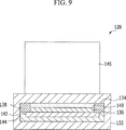
Wie in den
Der Heizkern
Eine Oberfläche des Kerngehäuses
Nach verschiedenen Ausgestaltungen der vorliegenden Erfindung ist der Heizkern
Danach wird das Kerngehäuse
Wenn der Heizkern
Nach verschiedenen Ausgestaltungen der vorliegenden Erfindung hat der Kanister
Gemäß den Ausführungsbeispielen wird die Entlüftungseffizienz des Kanisters
Da die dem Kanister
Da das PTC-Element
Da der erste Anschluss
Zur Vereinfachung der Erläuterung und zur genauen Definition in den beigefügten Ansprüchen, werden die Begriffe oben oder unten, innen, und so weiter verwendet, um Merkmale der Ausführungsbeispiele unter Bezugnahme auf die Positionen dieser Merkmale in den Figuren zu beschreiben.For ease of explanation and detailed definition in the appended claims, the terms upper or lower, inner, and so on are used to describe features of the embodiments with reference to the positions of these features in the figures.
Die vorstehenden Beschreibungen von spezifischen Ausführungsbeispielen der vorliegenden Erfindung dienen zum Zwecke der Darstellung und Beschreibung. Sie sollen nicht erschöpfend sein oder die Erfindung auf die genauen offenbarten Formen beschränken, wobei offensichtlich viele Modifikationen und Variationen im Lichte der obigen Lehren möglich sind. Die Ausführungsbeispiele wurden ausgewählt und beschrieben, um bestimmte Prinzipien der Erfindung und ihre praktische Anwendung zu erklären, um dadurch andere Fachleute in die Lage zu versetzen, verschiedene Ausführungsbeispiele der vorliegenden Erfindung zu machen und zu nutzen, sowie verschiedene Alternativen und Modifikationen davon. Es ist beabsichtigt, dass der Umfang der Erfindung durch die beigefügten Ansprüche und ihre Äquivalente definiert ist.The foregoing descriptions of specific embodiments of the present invention have been presented for purposes of illustration and description. They are not intended to be exhaustive or to limit the invention to the precise forms disclosed, obviously many modifications and variations are possible in light of the above teachings. The embodiments have been chosen and described to explain certain principles of the invention and its practical application, thereby enabling others skilled in the art to make and use various embodiments of the present invention, as well as various alternatives and modifications thereof. It is intended that the scope of the invention be defined by the appended claims and their equivalents.
ZITATE ENTHALTEN IN DER BESCHREIBUNG QUOTES INCLUDE IN THE DESCRIPTION
Diese Liste der vom Anmelder aufgeführten Dokumente wurde automatisiert erzeugt und ist ausschließlich zur besseren Information des Lesers aufgenommen. Die Liste ist nicht Bestandteil der deutschen Patent- bzw. Gebrauchsmusteranmeldung. Das DPMA übernimmt keinerlei Haftung für etwaige Fehler oder Auslassungen.This list of the documents listed by the applicant has been generated automatically and is included solely for the better information of the reader. The list is not part of the German patent or utility model application. The DPMA assumes no liability for any errors or omissions.
Zitierte PatentliteraturCited patent literature
- KR 10-2010-0113011 [0001] KR 10-2010-0113011 [0001]
Claims (20)
Applications Claiming Priority (2)
| Application Number | Priority Date | Filing Date | Title |
|---|---|---|---|
| KR1020100113011A KR101261945B1 (en) | 2010-11-12 | 2010-11-12 | Canister for vehicles and fuel evaporative system provided with the same |
| KR10-2010-0113011 | 2010-11-12 |
Publications (1)
| Publication Number | Publication Date |
|---|---|
| DE102011052145A1 true DE102011052145A1 (en) | 2012-05-16 |
Family
ID=45999041
Family Applications (1)
| Application Number | Title | Priority Date | Filing Date |
|---|---|---|---|
| DE201110052145 Withdrawn DE102011052145A1 (en) | 2010-11-12 | 2011-07-26 | CANISTER FOR VEHICLES AND FUEL EVAPORATION SYSTEM WITH THIS |
Country Status (5)
| Country | Link |
|---|---|
| US (1) | US8839768B2 (en) |
| JP (1) | JP2012102722A (en) |
| KR (1) | KR101261945B1 (en) |
| CN (1) | CN102465794B (en) |
| DE (1) | DE102011052145A1 (en) |
Cited By (1)
| Publication number | Priority date | Publication date | Assignee | Title |
|---|---|---|---|---|
| DE202019104867U1 (en) * | 2019-09-03 | 2020-12-07 | Voss Automotive Gmbh | Ventilation line for fuel tanks |
Families Citing this family (17)
| Publication number | Priority date | Publication date | Assignee | Title |
|---|---|---|---|---|
| KR101275753B1 (en) * | 2011-01-17 | 2013-06-14 | 코리아에프티 주식회사 | Canister for vehicle including controller for heater |
| US9222446B2 (en) * | 2011-08-11 | 2015-12-29 | GM Global Technology Operations LLC | Fuel storage system for a vehicle |
| US9353710B2 (en) * | 2012-12-10 | 2016-05-31 | Delphi Technologies, Inc. | Carbon heating element for evaporative emission canister |
| US9371804B2 (en) | 2013-04-18 | 2016-06-21 | U.S. Farathane Corporation | Self cleaning dust box assembly for use with controlled tube assemblies, such as forming a portion of a fresh air replacement line associated with a vehicle fuel tank |
| CN104175868B (en) * | 2013-05-21 | 2016-12-28 | 重庆长安汽车股份有限公司 | Automobile canister mounting structure |
| JP6297456B2 (en) * | 2014-09-16 | 2018-03-20 | 愛三工業株式会社 | Evaporative fuel processing equipment |
| JP2016065463A (en) | 2014-09-24 | 2016-04-28 | 愛三工業株式会社 | Evaporation fuel treatment device |
| CN104989564B (en) * | 2015-06-18 | 2017-06-27 | 江苏大学 | A vehicle-mounted fuel evaporation control device with temperature adjustment function |
| JP6314938B2 (en) * | 2015-08-18 | 2018-04-25 | トヨタ自動車株式会社 | Canister structure |
| US10040448B2 (en) * | 2015-11-12 | 2018-08-07 | Ford Global Technologies, Llc | Systems and methods for detection and mitigation of liquid fuel carryover in an evaporative emissions system |
| KR102119916B1 (en) * | 2015-12-08 | 2020-06-05 | 현대자동차주식회사 | Assembling structure for pheripheral components of canister |
| JP6639217B2 (en) * | 2015-12-17 | 2020-02-05 | 株式会社マーレ フィルターシステムズ | Canister |
| CN110878727B (en) * | 2019-11-18 | 2021-01-19 | 盐城工业职业技术学院 | Automobile engine fuel steam negative pressure recovery system and working method thereof |
| CN110953094B (en) * | 2019-12-30 | 2024-10-25 | 东风富士汤姆森调温器有限公司 | A fuel evaporation and desorption system for a small-displacement turbocharged vehicle and a control method thereof |
| JP7408487B2 (en) * | 2020-05-29 | 2024-01-05 | 株式会社Subaru | Vehicle fuel tank system and its abnormality diagnosis method |
| CN112879183A (en) * | 2021-02-24 | 2021-06-01 | 东风富士汤姆森调温器有限公司 | Heating ventilation pipe and fuel evaporation control system comprising same |
| CN116906227B (en) * | 2023-07-25 | 2026-03-03 | 江苏大学 | Fuel evaporation and emission control system and method for high-pressure fuel tank of hybrid electric vehicle |
Citations (1)
| Publication number | Priority date | Publication date | Assignee | Title |
|---|---|---|---|---|
| KR20100113011A (en) | 2009-04-10 | 2010-10-20 | 이부경 | Method for preparing sand aggregate |
Family Cites Families (16)
| Publication number | Priority date | Publication date | Assignee | Title |
|---|---|---|---|---|
| US4721846A (en) * | 1986-07-02 | 1988-01-26 | Casco Products Corporation | Canister heater with PTC wafer |
| JPH01147154A (en) | 1987-11-30 | 1989-06-08 | Texas Instr Japan Ltd | Fuel evaporative emission preventing device |
| JPH05223024A (en) | 1992-02-15 | 1993-08-31 | Mitsubishi Electric Corp | Device for restraining discharge of evaporated fuel gas |
| JP3465393B2 (en) * | 1995-01-06 | 2003-11-10 | トヨタ自動車株式会社 | Evaporative fuel processor for internal combustion engines |
| JP2910607B2 (en) * | 1995-02-24 | 1999-06-23 | トヨタ自動車株式会社 | Evaporative fuel treatment system for vehicles |
| JP3198865B2 (en) * | 1995-03-20 | 2001-08-13 | トヨタ自動車株式会社 | Failure diagnosis device for evaporation purge system |
| JP3322119B2 (en) * | 1996-03-04 | 2002-09-09 | 三菱電機株式会社 | Failure diagnosis device for fuel evaporation prevention device |
| JP2003021007A (en) * | 2001-07-03 | 2003-01-24 | Denso Corp | Canister |
| JP3891852B2 (en) * | 2002-01-31 | 2007-03-14 | 株式会社日本自動車部品総合研究所 | Fuel vapor processing apparatus for internal combustion engine |
| JP2004068696A (en) | 2002-08-06 | 2004-03-04 | Futaba Industrial Co Ltd | Canister |
| JP4419445B2 (en) * | 2003-06-12 | 2010-02-24 | トヨタ自動車株式会社 | Evaporative fuel processing system |
| JP2005023881A (en) * | 2003-07-04 | 2005-01-27 | Nissan Motor Co Ltd | Control device for hybrid vehicle |
| DE202005012394U1 (en) * | 2005-08-06 | 2005-12-08 | Microhellix Systems Gmbh | Electric heating module for airflow warming especially in vehicles, has heat emission section constructed in ring-form and especially circular, with heat conducting vanes arranged to extend radially |
| FR2890340A1 (en) | 2005-09-05 | 2007-03-09 | Inergy Automotive Systems Res | HEATING DEVICE FOR CANISTER |
| JP2009156030A (en) * | 2007-12-25 | 2009-07-16 | Mahle Filter Systems Japan Corp | Evaporated fuel treatment device |
| CN201351547Y (en) * | 2008-04-17 | 2009-11-25 | 周书忠 | Charcoal canister for gas filtration of car and motorcycle |
-
2010
- 2010-11-12 KR KR1020100113011A patent/KR101261945B1/en active Active
-
2011
- 2011-06-20 JP JP2011136258A patent/JP2012102722A/en not_active Withdrawn
- 2011-07-26 CN CN201110212977.6A patent/CN102465794B/en not_active Expired - Fee Related
- 2011-07-26 DE DE201110052145 patent/DE102011052145A1/en not_active Withdrawn
- 2011-07-29 US US13/194,678 patent/US8839768B2/en active Active
Patent Citations (1)
| Publication number | Priority date | Publication date | Assignee | Title |
|---|---|---|---|---|
| KR20100113011A (en) | 2009-04-10 | 2010-10-20 | 이부경 | Method for preparing sand aggregate |
Cited By (1)
| Publication number | Priority date | Publication date | Assignee | Title |
|---|---|---|---|---|
| DE202019104867U1 (en) * | 2019-09-03 | 2020-12-07 | Voss Automotive Gmbh | Ventilation line for fuel tanks |
Also Published As
| Publication number | Publication date |
|---|---|
| JP2012102722A (en) | 2012-05-31 |
| US8839768B2 (en) | 2014-09-23 |
| KR20120051527A (en) | 2012-05-22 |
| CN102465794B (en) | 2016-01-20 |
| US20120118273A1 (en) | 2012-05-17 |
| KR101261945B1 (en) | 2013-05-09 |
| CN102465794A (en) | 2012-05-23 |
Similar Documents
| Publication | Publication Date | Title |
|---|---|---|
| DE102011052145A1 (en) | CANISTER FOR VEHICLES AND FUEL EVAPORATION SYSTEM WITH THIS | |
| DE102004061809A1 (en) | Heating and / or cooling system for a motor vehicle | |
| DE102010060956B4 (en) | Container for vehicle and tanked fuel supply system | |
| DE19525542A1 (en) | Heating device | |
| DE2022911B2 (en) | Control device for a mixture-compressing externally ignited internal combustion engine to reduce the emission of harmful exhaust gas components | |
| DE102010055315A1 (en) | Apparatus for cooling and condensing fuel vapors | |
| DE102013219637A1 (en) | POWER PLANT COOLING SYSTEM AND MOTOR-DRIVEN VACUUM PUMP | |
| DE2610688A1 (en) | DEVICE FOR THE CONVERSION OF FUEL FOR A COMBUSTION ENGINE | |
| EP3237818B1 (en) | Sorption module | |
| DE2364455C3 (en) | Electric heater | |
| DE102014012706A1 (en) | Device for air conditioning a vehicle interior | |
| WO2002057615A1 (en) | Device and method for preventing fuel vapors from escaping from the intake system of an internal combustion engine | |
| DE102017208637B4 (en) | Exhaust system for a motor vehicle and a corresponding motor vehicle | |
| DE102020210216A1 (en) | Fuel tank ventilation system for a hybrid vehicle | |
| DE19913440A1 (en) | Fuel tank ventilation system for motor vehicles has tank constructed for max. operational pressure higher than ambient pressure and closeable ventilation valves | |
| DE102016123444B4 (en) | Reservoir valve device for a vehicle | |
| DE102009052863A1 (en) | A fuel cell assembly | |
| EP3555448B1 (en) | Method for testing the sealing tightness of a fuel tank system of an internal combustion engine | |
| EP0210360A1 (en) | Device for warming a target for practice target arrangements | |
| DE102011053515A1 (en) | Kraftstofftankverdampfungsgasspülsystem | |
| DE102012106598B4 (en) | Combustion device for liquid fuels and method therefor | |
| WO2012062312A2 (en) | Adsorption refrigeration machine driven by exhaust gas | |
| DE102011006192B4 (en) | Evaporator assembly, in particular for a fuel-powered vehicle heater or a reformer | |
| DE102020118119A1 (en) | Heat exchanger arrangement, method for operating a heat exchanger arrangement and drive device for a motor vehicle | |
| DE10360459A1 (en) | Conditioning system for a vehicle |
Legal Events
| Date | Code | Title | Description |
|---|---|---|---|
| R012 | Request for examination validly filed | ||
| R079 | Amendment of ipc main class |
Free format text: PREVIOUS MAIN CLASS: B60K0015035000 Ipc: F02M0033000000 |
|
| R012 | Request for examination validly filed |
Effective date: 20141117 |
|
| R079 | Amendment of ipc main class |
Free format text: PREVIOUS MAIN CLASS: B60K0015035000 Ipc: F02M0033000000 Effective date: 20141121 |
|
| R079 | Amendment of ipc main class |
Free format text: PREVIOUS MAIN CLASS: F02M0033000000 Ipc: F02M0033020000 |
|
| R002 | Refusal decision in examination/registration proceedings | ||
| R119 | Application deemed withdrawn, or ip right lapsed, due to non-payment of renewal fee |