DE102011050834A1 - Integrated circuit arrangement for sampling magnetic scale, has auxiliary group of Hall-effect sensors for sensing secondary track, which is arranged on two arcuate scanning paths with different curvatures - Google Patents
Integrated circuit arrangement for sampling magnetic scale, has auxiliary group of Hall-effect sensors for sensing secondary track, which is arranged on two arcuate scanning paths with different curvatures Download PDFInfo
- Publication number
- DE102011050834A1 DE102011050834A1 DE102011050834A DE102011050834A DE102011050834A1 DE 102011050834 A1 DE102011050834 A1 DE 102011050834A1 DE 102011050834 A DE102011050834 A DE 102011050834A DE 102011050834 A DE102011050834 A DE 102011050834A DE 102011050834 A1 DE102011050834 A1 DE 102011050834A1
- Authority
- DE
- Germany
- Prior art keywords
- track
- hall sensors
- scanning
- circuit arrangement
- hall
- Prior art date
- Legal status (The legal status is an assumption and is not a legal conclusion. Google has not performed a legal analysis and makes no representation as to the accuracy of the status listed.)
- Granted
Links
- 230000005355 Hall effect Effects 0.000 title abstract 2
- 238000005070 sampling Methods 0.000 title 1
- 239000000463 material Substances 0.000 claims description 62
- 238000012937 correction Methods 0.000 claims description 14
- 239000000696 magnetic material Substances 0.000 claims description 4
- 230000003213 activating effect Effects 0.000 claims description 2
- 238000011156 evaluation Methods 0.000 description 12
- 239000000758 substrate Substances 0.000 description 5
- 238000010586 diagram Methods 0.000 description 4
- 238000005259 measurement Methods 0.000 description 3
- 230000010363 phase shift Effects 0.000 description 3
- 230000000694 effects Effects 0.000 description 2
- 230000001105 regulatory effect Effects 0.000 description 2
- BUHVIAUBTBOHAG-FOYDDCNASA-N (2r,3r,4s,5r)-2-[6-[[2-(3,5-dimethoxyphenyl)-2-(2-methylphenyl)ethyl]amino]purin-9-yl]-5-(hydroxymethyl)oxolane-3,4-diol Chemical compound COC1=CC(OC)=CC(C(CNC=2C=3N=CN(C=3N=CN=2)[C@H]2[C@@H]([C@H](O)[C@@H](CO)O2)O)C=2C(=CC=CC=2)C)=C1 BUHVIAUBTBOHAG-FOYDDCNASA-N 0.000 description 1
- 230000006978 adaptation Effects 0.000 description 1
- 230000003321 amplification Effects 0.000 description 1
- 230000033228 biological regulation Effects 0.000 description 1
- 230000001276 controlling effect Effects 0.000 description 1
- 230000001419 dependent effect Effects 0.000 description 1
- 238000013461 design Methods 0.000 description 1
- 238000001514 detection method Methods 0.000 description 1
- 230000002349 favourable effect Effects 0.000 description 1
- 238000003199 nucleic acid amplification method Methods 0.000 description 1
- 230000000737 periodic effect Effects 0.000 description 1
- 238000012545 processing Methods 0.000 description 1
- 230000001629 suppression Effects 0.000 description 1
- 238000012549 training Methods 0.000 description 1
Images


Classifications
-
- G—PHYSICS
- G01—MEASURING; TESTING
- G01B—MEASURING LENGTH, THICKNESS OR SIMILAR LINEAR DIMENSIONS; MEASURING ANGLES; MEASURING AREAS; MEASURING IRREGULARITIES OF SURFACES OR CONTOURS
- G01B7/00—Measuring arrangements characterised by the use of electric or magnetic techniques
- G01B7/30—Measuring arrangements characterised by the use of electric or magnetic techniques for measuring angles or tapers; for testing the alignment of axes
-
- H—ELECTRICITY
- H03—ELECTRONIC CIRCUITRY
- H03M—CODING; DECODING; CODE CONVERSION IN GENERAL
- H03M1/00—Analogue/digital conversion; Digital/analogue conversion
- H03M1/06—Continuously compensating for, or preventing, undesired influence of physical parameters
- H03M1/0617—Continuously compensating for, or preventing, undesired influence of physical parameters characterised by the use of methods or means not specific to a particular type of detrimental influence
- H03M1/0675—Continuously compensating for, or preventing, undesired influence of physical parameters characterised by the use of methods or means not specific to a particular type of detrimental influence using redundancy
- H03M1/0678—Continuously compensating for, or preventing, undesired influence of physical parameters characterised by the use of methods or means not specific to a particular type of detrimental influence using redundancy using additional components or elements, e.g. dummy components
-
- H—ELECTRICITY
- H03—ELECTRONIC CIRCUITRY
- H03M—CODING; DECODING; CODE CONVERSION IN GENERAL
- H03M1/00—Analogue/digital conversion; Digital/analogue conversion
- H03M1/12—Analogue/digital converters
- H03M1/22—Analogue/digital converters pattern-reading type
- H03M1/24—Analogue/digital converters pattern-reading type using relatively movable reader and disc or strip
- H03M1/28—Analogue/digital converters pattern-reading type using relatively movable reader and disc or strip with non-weighted coding
- H03M1/287—Analogue/digital converters pattern-reading type using relatively movable reader and disc or strip with non-weighted coding using gradually changing slit width or pitch within one track; using plural tracks having slightly different pitches, e.g. of the Vernier or nonius type
Landscapes
- Physics & Mathematics (AREA)
- General Physics & Mathematics (AREA)
- Engineering & Computer Science (AREA)
- Theoretical Computer Science (AREA)
- Transmission And Conversion Of Sensor Element Output (AREA)
- Measurement Of Length, Angles, Or The Like Using Electric Or Magnetic Means (AREA)
Abstract
Description
Die Erfindung betrifft eine integrierte Schaltungsanordnung zur Abtastung einer magnetischen Maßverkörperung, die eine Hauptspur mit n periodisch angeordneten Polpaaren und eine Nebenspur mit einer von n abweichenden Anzahl an periodisch angeordneten Polpaaren, insbesondere n – 1 Polpaaren, aufweist, mit einer ersten Gruppe Hallsensoren zur Abtastung der Hauptspur und mit einer zweiten Gruppe Hallsensoren zur Abtastung der Nebenspur. Ferner betrifft die Erfindung eine Positionsmessvorrichtung, die eine solche magnetischen Maßverkörperung und eine solche integrierte Schaltungsanordnung umfasst.The invention relates to an integrated circuit arrangement for scanning a magnetic measuring standard, which has a main track with n periodically arranged pole pairs and a secondary track with a different number of n periodically arranged pole pairs, in particular n - 1 pole pairs, with a first group of Hall sensors for scanning the Main track and with a second group of Hall sensors for scanning the secondary track. Furthermore, the invention relates to a position measuring device comprising such a magnetic measuring standard and such an integrated circuit arrangement.
Positionsmessvorrichtungen werden u. a. zur Bestimmung der Position beweglicher Bauteile verwendet, beispielsweise zur Erfassung einer Längs- oder Winkelstellung. Die Bauteile können hierzu mit einer Maßverkörperung versehen sein, welche von einem oder mehreren Sensoren abgetastet wird.Position measuring devices are u. a. used to determine the position of movable components, for example, to detect a longitudinal or angular position. For this purpose, the components can be provided with a material measure, which is scanned by one or more sensors.
In der
Zur Abtastung der beiden Spuren wird eine Schaltungsanordnung mit magnetischen Sensoren verwendet, welche als Hallsensoren ausgebildet sind. Die Hallsensoren sind in zwei Gruppen unterteilt, wobei durch die Hallsensoren der ersten Gruppe die Hauptspur abgetastet wird und durch die Hallsensoren der zweiten Gruppe die Nebenspur abgetastet wird.For scanning the two tracks, a circuit arrangement with magnetic sensors is used, which are designed as Hall sensors. The Hall sensors are divided into two groups, wherein the main track is scanned by the Hall sensors of the first group and the secondary track is scanned by the Hall sensors of the second group.
Um eine möglichst genaue Bestimmung der Position der Maßverkörperung zu ermöglichen, ist es vorteilhaft, wenn die Hallsensoren bei Bewegung der Maßverkörperung entlang der Abtastbahn in etwa in der Mitte der jeweiligen abgetasteten Spur geführt sind. In diesem Zusammenhang besteht allerdings der Nachteil, dass eine Schaltungsanordnung in der Regel nur an eine einzige Maßverkörperung angepasst ist. So kann eine Schaltungsanordnung, die an eine Maßverkörperung mit einem bestimmten Radius angepasst ist, nicht ohne Weiteres mit einer Maßverkörperung verwendet werden, die einen anderen Radius oder einen geraden Verlauf hat. Falls eine Schaltungsanordnung mit einer anderen Maßverkörperung betrieben wird, treten nämlich Messungenauigkeiten bei der Positionsbestimmung auf.In order to enable the most accurate possible determination of the position of the material measure, it is advantageous if the Hall sensors are guided in movement of the material measure along the scanning path approximately in the middle of the respective scanned track. In this context, however, there is the disadvantage that a circuit arrangement is usually adapted only to a single material measure. Thus, a circuit arrangement that is adapted to a material measure with a certain radius, not readily used with a material measure that has a different radius or a straight course. If a circuit arrangement is operated with a different material measure, measurement inaccuracies occur during the position determination.
Aufgabe der Erfindung ist es daher, eine integrierte Schaltungsanordnung anzugeben, die bei ausreichender Genauigkeit mit verschiedenen Maßverkörperungen verwendet werden kann.The object of the invention is therefore to provide an integrated circuit arrangement which can be used with sufficient dimensional accuracy with sufficient dimensional standards.
Bei einer eingangs genannten integrierten Schaltungsanordnung wird diese Aufgabe dadurch gelöst, dass die Hallsensoren einer Gruppe auf mindestens zwei bogenförmigen Abtastbahnen mit unterschiedlicher Krümmung angeordnet sind. Die bogenförmigen Abtastbahnen können zur Abtastung der Hauptspur und/oder der Nebenspur der Maßverkörperung vorgesehen sein. Hierzu können die Abtastbahnen einer Gruppe in einem gemeinsamen Korridor auf dem Substrat der Schaltungsanordnung angeordnet sein.In an integrated circuit arrangement mentioned above, this object is achieved in that the Hall sensors of a group are arranged on at least two arcuate scanning paths with different curvature. The arcuate scanning paths may be provided for scanning the main track and / or the secondary track of the material measure. For this purpose, the scanning paths of a group can be arranged in a common corridor on the substrate of the circuit arrangement.
Durch die bogenförmigen Abtastbahnen können Spuren unterschiedlicher Krümmung abgetastet werden, so dass die Schaltungsanordnung für verschiedene Maßverkörperungen verwendbar ist. Die Krümmungen der Abtastbahnen können jeweils an die Krümmungen der Spuren der Maßverkörperungen angepasst sein. Die erste bogenförmige Abtastbahn kann auf die Abtastung einer Spur einer ersten Maßverkörperung abgestimmt sein, während die zweite bogenförmige Abtastbahn auf die Abtastung einer Spur einer zweiten Maßverkörperung ausgelegt sein kann. Somit kann die integrierte Schaltungsanordnung die Positionsbestimmung mit hoher Genauigkeit auch für unterschiedlich gekrümmte Maßverkörperungen ermöglichen.Traces of different curvature can be scanned through the arcuate scanning paths, so that the circuit arrangement can be used for different measuring graduations. The curvatures of the scanning paths can each be adapted to the curvatures of the tracks of the material measures. The first arcuate scanning path can be tuned to the scanning of a track of a first measuring graduation, while the second arcuate scanning path can be designed to scan a track of a second material measure. Thus, the integrated circuit arrangement can enable the position determination with high accuracy even for different curved measuring standards.
Die Abtastbahnen können jeweils die gleiche Anzahl an Hallsensoren aufweisen und insbesondere mit Hallsensoren ausgestattet sein, die jeweils einer einzigen Abtastbahn zugehörig sind. Gemäß einer vorteilhaften Ausgestaltung weist die Schaltungsanordnung aber mindestens einen Multibahn-Hallsensor auf, der auf mehreren Abtastbahnen angeordnet ist. Der Multibahn-Hallsensor kann mehrfach verwendet werden, nämlich sowohl für eine erste Abtastbahn als auch für eine zweite Abtastbahn, wodurch die Anzahl erforderlicher Hallsensoren verringert werden kann.The scanning paths may each have the same number of Hall sensors and be equipped in particular with Hall sensors, which are each associated with a single scanning path. According to an advantageous embodiment, the circuit arrangement but at least one multi-track Hall sensor, which is arranged on a plurality of scanning paths. The multi-track Hall sensor can be used multiple times, namely for both a first scanning path and for a second scanning path, whereby the number of required Hall sensors can be reduced.
Bevorzugt umfasst ein aus mehreren Abtastbahnen bestehendes Abtastbahn-Bündel zwei Multibahn-Hallsensoren. Über die beiden Multibahn-Hallsensoren kann ein gemeinsamer Abtastbereich definiert werden, welcher in mehreren Abtastbahnen enthalten ist, wodurch die Gesamtanzahl an Hallsensoren weiter reduziert werden kann.A scan path bundle consisting of several scan paths preferably comprises two multi-track Hall sensors. Via the two multi-track Hall sensors, a common scanning range can be defined, which is contained in several scanning paths, whereby the total number of Hall sensors can be further reduced.
Neben den Multibahn-Hallsensoren können die Abtastbahnen auch Singlebahn-Hallsensoren aufweisen, die lediglich auf einer Abtastbahn angeordnet sind. Besonders vorteilhaft ist eine Ausgestaltung, bei der auf einer Abtastbahn mindestens ein Multibahn-Hallsensor und mehrere Singlebahn-Hallsensoren liegen. Der Multibahn-Hallsensor kann vorzugsweise in der Mitte der Abtastbahn angeordnet sein. Insofern definiert der Multibahn-Hallsensor einen Schnittpunkt einer Abtastbahn mit einer anderen Abtastbahn. Bei Verwendung von zwei Multibahn-Hallsensoren werden zwei Schnittpunkte der Abtastbahnen-Schar festgelegt. Die Krümmung und der weitere Verlauf der einzelnen Abtastbahnen werden durch die Lage der insbesondere im Randbereich der Abtastbahn angeordneten Singlebahn-Hallsensoren bestimmt.In addition to the multi-track Hall sensors, the scanning paths can also have single-track Hall sensors that only on a scanning path are arranged. Particularly advantageous is an embodiment in which at least one multi-track Hall sensor and several single-track Hall sensors are located on a scanning path. The multi-track Hall sensor may preferably be arranged in the middle of the scanning path. In this respect, the multi-track Hall sensor defines an intersection of a scan path with another scan path. When using two multi-track Hall sensors, two intersections of the scanning paths are set. The curvature and the further course of the individual scanning paths are determined by the position of the single-track Hall sensors, which are arranged in particular in the edge region of the scanning path.
Bevorzugt sind die Singlebahn-Hallsensoren in Umfangsrichtung der jeweiligen bogenförmigen Abtastbahn gegeneinander versetzt angeordnet. Durch den Versatz kann erreicht werden, dass Singlebahn-Hallsensoren auch in solchen Bereichen der Abtastbahnen angeordnet werden können, die nur einen geringen Abstand zu einer anderen Abtastbahn aufweisen, so dass sich keine Probleme hinsichtlich der Anordnung der Hallsensoren auf der integrierten Schaltungsanordnung ergeben. Ferner können die Sensoren derart gegeneinander versetzt sein, dass sie entlang ihrer Abtastbahn unterschiedliche Abstände zu dem benachbarten Multibahn-Hallsensor aufweisen, wodurch Maßverkörperungen mit unterschiedlicher Polpaar-Periode abgetastet werden können.Preferably, the single-track Hall sensors are arranged offset from one another in the circumferential direction of the respective arcuate scanning path. The offset can be achieved that single-track Hall sensors can be arranged in those areas of the scanning paths, which have only a small distance to another scanning path, so that there are no problems in terms of the arrangement of the Hall sensors on the integrated circuit arrangement. Furthermore, the sensors can be offset relative to one another in such a way that they have different distances from the adjacent multi-track Hall sensor along their scanning path, as a result of which measuring scales with a different pole pair period can be scanned.
Um die Abtastung drehbar gelagerter Maßverkörperungen zu ermöglichen, können die gekrümmten Abtastbahnen als Kreisbögen ausgebildet sein, welche sich in einem oder mehreren Punkten schneiden. In einer derartigen Ausgestaltung fallen die Mittelpunkte der Kreise aufgrund der unterschiedlichen Radien nicht zusammen. Bevorzugt können die Mittelpunkte der bogenförmigen Abtastbahnen aber auf einer gemeinsamen Geraden liegen. Darüber hinaus können auch andere Bogenformen verwendet werden, wie beispielsweise ellipsenförmige Abtastbahnen. Bei diesen werden die Schnittpunkte der Halbachsen als Mittelpunkte bezeichnet, die auf einer Geraden angeordnet sein können.In order to enable the scanning of rotatably mounted material measures, the curved scanning paths may be formed as circular arcs which intersect at one or more points. In such an embodiment, the centers of the circles do not coincide due to the different radii. However, the centers of the arcuate scanning paths may preferably lie on a common straight line. In addition, other bow shapes may be used, such as elliptical scan paths. In these, the intersections of the semi-axes are referred to as centers, which can be arranged on a straight line.
In diesem Zusammenhang hat es sich ferner als vorteilhaft erwiesen, wenn zwei Multibahn-Hallsensoren symmetrisch zu der Geraden liegen. Ferner können auch zwei Singlebahn-Hallsensoren einer Abtastbahn symmetrisch zu der Geraden liegen, so dass die durch die Singlebahn-Hallsensoren definierte Abtastbahn spiegelsymmetrisch zu der Geraden verläuft.In this context, it has also proven to be advantageous if two multi-track Hall sensors are symmetrical to the line. Furthermore, two single-track Hall sensors of a scanning path may be symmetrical to the straight line, so that the scanning path defined by the single-track Hall sensors is mirror-symmetrical to the straight line.
Im Hinblick auf die Auswertung der von den Sensoren erzeugten Hallspannungen hat es sich als vorteilhaft erwiesen, wenn mindestens vier Hallsensoren auf jeweils einer Abtastspur angeordnet sind, so dass aus den Hallspannungen jeweils zweier Hallsensoren ein Differenzsignal erzeugt werden kann, welches frei vom Einfluss magnetischer Gleichfelder ist. Bevorzugt liegen auf einer Abtastbahn zwei Multibahn-Hallsensoren und zwei Singlebahn-Hallsensoren, die jeweils symmetrisch zu einer gemeinsamen Geraden angeordnet sind.With regard to the evaluation of the Hall voltages generated by the sensors, it has proven to be advantageous if at least four Hall sensors are arranged on one scanning track, so that a differential signal can be generated from the Hall voltages of two Hall sensors, which is free from the influence of magnetic DC fields , Preferably lie on a scanning path two multi-track Hall sensors and two single-track Hall sensors, which are each arranged symmetrically to a common line.
Um eine Verwendung der integrierten Schaltungsanordnung auch mit solchen Maßverkörperungen zu ermöglichen, welche entlang einer Geraden angeordnet sind, ist gemäß einer vorteilhaften Ausgestaltung vorgesehen, dass eine gerade Abtastbahn, auf welcher Hallsensoren angeordnet sind, vorgesehen ist. Die Gerade kann hierbei als Kreisbogen mit unendlichem Radius verstanden werden. Insofern wird als erfindungsgemäße Ausgestaltung auch eine Schaltungsanordnung verstanden, die für Hallsensoren einer Gruppe eine gerade Abtastbahn und eine gekrümmte Abtastbahn mit endlichem Radius aufweist.In order to enable use of the integrated circuit arrangement with such material measures, which are arranged along a straight line, it is provided according to an advantageous embodiment that a straight scanning path, on which Hall sensors are arranged, is provided. The straight line can be understood here as a circular arc with infinite radius. In this respect, a configuration according to the invention is understood as meaning a circuit arrangement which has a straight scanning path and a curved scanning path with finite radius for Hall sensors of a group.
Sofern Multibahn-Sensoren zur Anwendung kommen, können diese auch auf der geraden Abtastbahn angeordnet sein. Durch die zusätzliche gerade Abtastbahn können mit der integrierten Schaltungsanordnung sowohl linear ausgebildete als auch bogenförmige Maßverkörperungen abgetastet werden.If multi-path sensors are used, they can also be arranged on the straight scanning path. As a result of the additional straight scanning path, both linearly formed and curved measuring graduations can be scanned with the integrated circuit arrangement.
Die Auswahl der jeweiligen bogenförmigen oder geraden Abtastbahn kann durch eine insbesondere in der Schaltungsanordnung enthaltene Umschalteinheit erfolgen. Gemäß einer bevorzugten Ausgestaltung ist die Umschalteinheit zur Aktivierung von Hallsensoren einer ausgewählten Abtastbahn mit den Hallsensoren verbunden. Mittels der Umschalteinheit können die Hallsensoren an- und abgeschaltet werden, wodurch die Schaltungsanordnung derart umkonfiguriert werden kann, dass je nach Art und Krümmung der Maßverkörperung eine Abtastbahn deaktiviert und eine andere Abtastbahn aktiviert wird.The selection of the respective arcuate or straight scanning path can be effected by a switching unit, in particular in the circuit arrangement. According to a preferred embodiment, the switching unit for activating Hall sensors of a selected scanning path is connected to the Hall sensors. By means of the switching unit, the Hall sensors can be switched on and off, whereby the circuit arrangement can be reconfigured in such a way that, depending on the type and curvature of the material measure, one scanning path is deactivated and another scanning path is activated.
Weiter ist es vorteilhaft, wenn die Schaltungsanordnung eine mit den Hallsensoren verbundene Auswerteeinheit zur Berechnung eines Positionswertes aufweist, welcher der Position der Maßverkörperung gegenüber der Schaltungsanordnung entspricht. Durch eine zusammen mit den Hallsensoren auf einem Substrat integrierte Auswerteeinheit kann eine kompakte Bauform ermöglicht werden.Further, it is advantageous if the circuit arrangement has an evaluation unit connected to the Hall sensors for calculating a position value which corresponds to the position of the material measure relative to the circuit arrangement. By means of an evaluation unit integrated on a substrate together with the Hall sensors, a compact design can be made possible.
Die Positionserfassung mittels der Auswerteeinheit kann wie folgt ausgestaltet sein: Aus den Signalen der Hallsensoren, welche die Hauptspur abtasten, kann ein relativer Hauptspur-Positionswert gebildet werden, der die Position der Maßverkörperung bezüglich einer Polpaar-Periode der Hauptspur angibt. Aus den Signalen der Hallsensoren, welche die Nebenspur abtasten, kann ein relativer Nebenspur-Positionswert gebildet werden, welcher die Position der Maßverkörperung bezüglich einer Periode der Nebenspur angibt. Aus der Differenz der Phasenwinkel zwischen Hauptspur und Nebenspur, bzw. aus der Differenz des Hauptspur-Positionswertes und des Nebenspur-Positionswertes, kann ein Positionswert gebildet werden, welcher die Position der Maßverkörperung bezüglich der Länge oder des Umfangs der Maßverkörperung angibt.The position detection by means of the evaluation unit can be configured as follows: From the signals of the Hall sensors, which scan the main track, a relative main track position value can be formed, which indicates the position of the material measure with respect to a pole pair period of the main track. From the signals of the Hall sensors, which scan the secondary track, a relative secondary track position value can be formed, which the Indicates the position of the material measure with respect to a period of the secondary track. From the difference of the phase angle between main track and secondary track, or from the difference of the main track position value and the secondary track position value, a position value can be formed, which indicates the position of the material measure with respect to the length or the circumference of the material measure.
In diesem Zusammenhang hat es sich ferner als vorteilhaft erwiesen, wenn eine Korrektureinheit zur Korrektur des Positionswertes vorgesehen ist, die derart ausgestaltet ist, dass der Verlauf des korrigierten Positionswertes über der Position der Maßverkörperung linearisiert ist. Die Differenz der Phasenwinkel zwischen Hauptspur und Nebenspur sollte nämlich theoretisch betrachtet linear verlaufen. Ungenauigkeiten in der Ausbildung oder der Platzierung der Maßverkörperung können aber zu Schwankungen und somit zu Abweichungen der Linearform führen. Hierdurch wird die Genauigkeit der Positionsmessung beeinträchtigt. In der Korrektureinheit kann ein vorgegebener Korrekturverlauf, insbesondere in einer Tabelle, hinterlegt sein, anhand dessen die Schwankungen derart korrigiert werden können, dass sich ein linearer Verlauf ergibt.In this context, it has also proven to be advantageous if a correction unit is provided for correcting the position value, which is designed such that the course of the corrected position value is linearized over the position of the material measure. The difference in the phase angle between the main track and the secondary track should theoretically be linear. However, inaccuracies in the training or the placement of the material measure can lead to fluctuations and thus deviations of the linear shape. This impairs the accuracy of the position measurement. A predetermined course of correction, in particular in a table, can be stored in the correction unit, by means of which the fluctuations can be corrected in such a way that a linear progression results.
Darüber hinaus hat es sich im Hinblick auf die Auswertung der von den Hallsensoren erzeugten Signale als vorteilhaft erwiesen, wenn zwei Regelungseinheiten zur getrennten Regelung der Amplitude der Hallsensoren der ersten Gruppe und der Amplitude der Hallsensoren der zweiten Gruppe vorgesehen sind. Durch die Regelungseinheiten können die Amplituden der Hallsensoren der jeweiligen Gruppe unabhängig voneinander ausgeregelt werden, so dass eine Veränderung der Amplitude eines Sensors der ersten Gruppe die Regelung der Amplitude der zweiten Gruppe nicht beeinflussen kann. Solche Veränderungen können sich z. B. durch eine Verkippung der integrierten Schaltungsanordnung gegenüber der Maßverkörperung ergeben. Anhand der getrennten Regelungsvorrichtungen kann der Einfluss von Verkippungen auf die Messgenauigkeit verringert werden.In addition, it has proved to be advantageous with regard to the evaluation of the signals generated by the Hall sensors when two control units for separate control of the amplitude of the Hall sensors of the first group and the amplitude of the Hall sensors of the second group are provided. By means of the control units, the amplitudes of the Hall sensors of the respective group can be regulated independently of one another, so that a change in the amplitude of a sensor of the first group can not influence the regulation of the amplitude of the second group. Such changes can z. B. result by tilting the integrated circuit arrangement relative to the material measure. By means of the separate control devices, the influence of tilting on the measuring accuracy can be reduced.
Ein weiterer Gegenstand der Erfindung ist eine Positionsmessvorrichtung mit einer magnetischen Maßverkörperung, die eine Hauptspur mit n periodisch angeordneten Polpaaren und eine Nebenspur mit einer von n abweichenden Anzahl an periodisch angeordneten Polpaaren, insbesondere n – 1 Polpaaren, aufweist. Bei einer derartigen Positionsmessvorrichtung wird zur Lösung der eingangs genannten Aufgabe vorgeschlagen, dass eine bereits beschriebene integrierte Schaltungsanordnung vorgesehen ist, so dass anhand der bogenförmigen Abtastbahnen Spuren unterschiedlicher Krümmung abgetastet werden können.Another object of the invention is a position measuring device with a magnetic measuring standard, which has a main track with n periodically arranged pole pairs and a secondary track with a non-n number of periodically arranged pole pairs, in particular n - 1 pole pairs. In such a position measuring device is proposed to solve the above-mentioned problem that an already described integrated circuit arrangement is provided so that traces of different curvature can be scanned on the basis of the arcuate scanning paths.
Die Maßverkörperung kann auf einem Kreisbogen, z. B. dem stirnseitigen Umfang eines Polrads, angeordnet sein. Die Maßverkörperung kann aber auch entlang einer Geraden verlaufen und beispielsweise stabförmig ausgebildet sein. Auf Grund einer bereits beschriebenen Umschaltmöglichkeit zwischen den Hallsensoren bzw. den Abtastbahnen, kann die Schaltungsanordnung folglich für eine Mehrzahl unterschiedlicher Maßverkörperungen und somit Messanordnungen eingesetzt werden.The material measure can be on a circular arc, z. B. the frontal circumference of a Polrads be arranged. However, the material measure can also run along a straight line and be designed, for example, rod-shaped. Due to an already described switching possibility between the Hall sensors or the scanning paths, the circuit arrangement can consequently be used for a plurality of different measuring standards and thus measuring arrangements.
Bei einer kreisbogenförmigen Maßverkörperung hat es sich als besonders vorteilhaft erwiesen, wenn die Krümmung mindestens einer bogenförmigen Abtastbahn an die Krümmung des Kreisbogens angepasst ist, so dass eine Abtastung erreicht werden kann, bei der die abtastenden Hallsensoren alle im gleichen Abstand zu der Mitte der abzutastenden Spur der magnetischen Maßverkörperung angeordnet sind.In the case of an arcuate measuring graduation, it has proven to be particularly advantageous if the curvature of at least one arcuate scanning path is matched to the curvature of the circular arc, so that a scanning can be achieved in which the scanning Hall sensors are all at the same distance from the center of the track to be scanned the magnetic measuring standard are arranged.
Ferner ist es bevorzugt, wenn die Maßverkörperung um eine Drehachse drehbar ist, wobei die integrierte Schaltungsanordnung abseits der Drehachse angeordnet ist. Bei einer „off-axis”-Positionierung der integrierten Schaltungsanordnung kann im Bereich der Drehachse ein Freiraum verbleiben, der zur Montage weiterer Komponenten oder zur Lagerung der Drehachse nutzbar ist.Furthermore, it is preferred if the material measure is rotatable about an axis of rotation, wherein the integrated circuit arrangement is arranged away from the axis of rotation. In the case of an "off-axis" positioning of the integrated circuit arrangement, a free space can remain in the area of the axis of rotation which can be used for mounting further components or for mounting the axis of rotation.
Gemäß einer weiteren vorteilhaften Ausgestaltung sind mehrere Hallsensoren in einem Abstand voneinander angeordnet, der 90° der Periode der Polpaare der Maßverkörperung entspricht. Die Hallsensoren können ein Sinussignal sowie ein Cosinussignal erzeugen, welche 90° gegeneinander verschoben sind. Hierdurch werden eine einfache Auswertung und zugleich eine hochgenaue Messung ermöglicht.According to a further advantageous embodiment, a plurality of Hall sensors are arranged at a distance from one another which corresponds to 90 ° of the period of the pole pairs of the material measure. The Hall sensors can generate a sinusoidal signal as well as a cosine signal, which are shifted 90 ° from each other. This allows a simple evaluation and at the same time a highly accurate measurement.
Des Weiteren kann es bei Positionsmessvorrichtungen erwünscht sein, den Messbereich über die Länge der Hauptspur hinaus zu vergrößern. in diesem Zusammenhang hat es sich als vorteilhaft herausgestellt, wenn eine zweite Nebenspur und eine zweite, mit der ersten Schaltungsanordnung verbundene Schaltungsanordnung vorgesehen sind, welche Hallsensoren zur Abtastung der Hauptspur und Hallsensoren zur Abtastung der zweiten Nebenspur aufweist.Furthermore, with position measuring devices, it may be desirable to increase the measuring range beyond the length of the main track. In this context, it has been found to be advantageous if a second secondary track and a second circuit arrangement connected to the first circuit arrangement are provided which has Hall sensors for scanning the main track and Hall sensors for scanning the second secondary track.
Soll der Messbereich k·n Perioden der Hauptspur betragen, kann die zweite Nebenspur n – k Polpaare aufweisen, wobei k < n ist. Anhand der Abtastung einer zweiten Nebenspur kann ein zweiter Nebenspur-Positionswert ermittelt werden, welcher die Position der Maßverkörperung bezüglich einer Periode der zweiten Nebenspur angibt. Anhand des von der ersten Schaltungsanordnung berechneten Positionswertes und des zweiten Nebenspur-Positionswertes kann dann ein erweiterter Positionswert ermittelt werden, welcher die Position der Maßverkörperung bezüglich der Länge des erweiterten Messbereichs angibt.If the measuring range is to be k × n periods of the main track, the second secondary track may have n-k pole pairs, where k <n. On the basis of the scanning of a second secondary track, a second secondary track position value can be determined, which indicates the position of the material measure with respect to a period of the second secondary track. Based on the position value calculated by the first circuit arrangement and the second secondary track Position value can then be determined an extended position value, which indicates the position of the material measure with respect to the length of the extended measuring range.
Weitere Vorteile und Einzelheiten der Erfindung werden nachfolgend anhand der in den Figuren dargestellten Ausführungsbeispiele beschrieben. Hierbei zeigtFurther advantages and details of the invention are described below with reference to the embodiments illustrated in the figures. This shows
In der
Die Maßverkörperung
Der Abstand zweier Nordpole N bzw. zweier Südpole S einer Spur
Die Spuren
Zur Abtastung der bogenförmigen Spuren
In
Die Hallsensoren
Die Hallsensoren
Die zweite Gruppe umfasst acht Hallsensoren
Wie ferner aus
In dem Ausführungsbeispiel sind auf einer Abtastbahn
Des Weiteren sind die einzelnen Abtastbahnen
Neben der Krümmung unterscheiden sich die einzelnen Abtastbahnen
Zur Abtastung einer Maßverkörperung
Über eine schematisch dargestellte, vorzugsweise integrierte Umschalteinheit
Wird nun anstatt der Maßverkörperung
Bei Verwendung einer Maßverkörperung
Um auch Maßverkörperungen
Zusätzlich zu den in der
Gemäß dem Ausführungsbeispiel sind lediglich die Hallsensoren
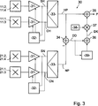
Die
Die erste Hallsensoren-Gruppe
The first Hall sensor group
Die Verstärker
Die Amplituden des Sinussignals SH und des Cosinussignals CH der Hauptspur-Sensoren
Dadurch können Temperaturschwankungen und Verkippungen zwischen der Schaltungsanordnung
Die Ausgänge der Verstärker
Aufgrund der um eins voneinander abweichenden Anzahl an Perioden der Hauptspur
Bei idealer Abtastung der Maßverkörperung
Dieser Effekt soll anhand der
In einem nach Abschluss der Fertigung und vor Inbetriebnahme der Positionsmessvorrichtung ausgeführten Teach-Lauf kann die Abweichung des tatsächlichen Verlaufs des Wertes DD von dem idealen linearen Verlauf erkannt werden und entsprechende Korrekturwerte C können berechnet werden, so dass sich nach der Korrektur ein Verlauf fkorr ergibt. Der Korrekturwert C an einer Position ergibt sich aus der Differenz des idealen linearen Verlaufs zum gemessenen Verlauf fmess.In a teach run executed after completion of the production and before the position measuring device is put into operation, the deviation of the actual course of the value DD from the ideal linear course can be detected and corresponding correction values C can be calculated so that a course f corr then results after the correction , The correction value C at a position results from the difference between the ideal linear progression and the measured profile f mess .
Die Korrekturwerte C können in Form einer Tabelle in einer in
Der absolute digitale Positionswert P bildet sich aus dem grob aufgelösten Differenzwert DK, welcher die Position innerhalb einer Umdrehung der Maßverkörperung
In der Auswerteeinheit
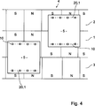
In der
Zudem weist die Positionsmessvorrichtung neben einer ersten integrierten Schaltungsanordnung
Aus Gründen der Übersichtlichkeit sind in der
Anhand der Abtastung der zweiten Nebenspur
Durch die vorstehend beschriebenen Positionsmessvorrichtungen mit einer Gruppe Hallsensoren
BezugszeichenlisteLIST OF REFERENCE NUMBERS
- 11
- Hauptspurmain track
- 22
- Nebenspuradjacent lane
- 33
- Nebenspuradjacent lane
- 44
- MaßverkörperungMeasuring standard
- 55
- integrierte Schaltungsanordnungintegrated circuit arrangement
- 66
- Polpaarpole pair
- 1010
- Abtastbahnscan path
- 11.1–11.411.1-11.4
- HallsensorHall sensor
- 2020
- Abtastbahnscan path
- 21.1–21.821.1-21.8
- HallsensorHall sensor
- 3030
- Auswerteeinheitevaluation
- 3131
- Verstärkeramplifier
- 3232
- Regelungseinheitcontrol unit
- 3333
- Sinus/Digital-WandlerSine / digital converter
- 3434
- Subtrahierersubtractor
- 3535
- Addiereradder
- 3636
- Addiereradder
- 3737
- Multiplizierermultipliers
- 3838
- Konstanteconstant
- 3939
- Tabelletable
- 4040
- Umschalteinheitswitching
- CC
- Korrekturwertcorrection value
- CH, CNCH, CN
- Cosinussignalcosine
- DD
- Drehachseaxis of rotation
- DD, DKDD, DK
- Differenzwertdifference value
- ff
- Funktionfunction
- kk
- natürliche Zahl > 1natural number> 1
- LL
- Länge der MaßverkörperungLength of the material measure
- M1, M2, M3M1, M2, M3
- MittelpunktFocus
- P, HP, NPP, HP, NP
- Positionswertposition value
- PH, PNPH, PN
- Periodeperiod
- nn
- natürliche Zahl > 1natural number> 1
- NN
- NordpolNorth Pole
- SS
- SüdpolSouth Pole
- SH, SNSH, SN
- Sinussignalsinewave
ZITATE ENTHALTEN IN DER BESCHREIBUNG QUOTES INCLUDE IN THE DESCRIPTION
Diese Liste der vom Anmelder aufgeführten Dokumente wurde automatisiert erzeugt und ist ausschließlich zur besseren Information des Lesers aufgenommen. Die Liste ist nicht Bestandteil der deutschen Patent- bzw. Gebrauchsmusteranmeldung. Das DPMA übernimmt keinerlei Haftung für etwaige Fehler oder Auslassungen.This list of the documents listed by the applicant has been generated automatically and is included solely for the better information of the reader. The list is not part of the German patent or utility model application. The DPMA assumes no liability for any errors or omissions.
Zitierte PatentliteraturCited patent literature
- US 4786891 A [0003] US 4786891 A [0003]
Claims (10)
Priority Applications (1)
| Application Number | Priority Date | Filing Date | Title |
|---|---|---|---|
| DE102011050834.1A DE102011050834B4 (en) | 2011-06-03 | 2011-06-03 | Integrated circuit arrangement with Hall sensors and position measuring device |
Applications Claiming Priority (1)
| Application Number | Priority Date | Filing Date | Title |
|---|---|---|---|
| DE102011050834.1A DE102011050834B4 (en) | 2011-06-03 | 2011-06-03 | Integrated circuit arrangement with Hall sensors and position measuring device |
Publications (2)
| Publication Number | Publication Date |
|---|---|
| DE102011050834A1 true DE102011050834A1 (en) | 2012-12-06 |
| DE102011050834B4 DE102011050834B4 (en) | 2022-02-17 |
Family
ID=47173108
Family Applications (1)
| Application Number | Title | Priority Date | Filing Date |
|---|---|---|---|
| DE102011050834.1A Active DE102011050834B4 (en) | 2011-06-03 | 2011-06-03 | Integrated circuit arrangement with Hall sensors and position measuring device |
Country Status (1)
| Country | Link |
|---|---|
| DE (1) | DE102011050834B4 (en) |
Cited By (5)
| Publication number | Priority date | Publication date | Assignee | Title |
|---|---|---|---|---|
| DE102019103465A1 (en) * | 2019-02-12 | 2020-08-13 | Ic-Haus Gmbh | Position measuring device for measuring an absolute position |
| CN111900961A (en) * | 2020-08-24 | 2020-11-06 | 国网山东省电力公司滨州市沾化区供电公司 | Waveform signal generator |
| CN116164778A (en) * | 2021-11-25 | 2023-05-26 | 迈来芯电子科技有限公司 | Position sensor with main rail and Norus rail |
| US11920927B2 (en) | 2021-05-03 | 2024-03-05 | Vishay MCB Industrie S.A.S. | Position encoder with combined inductive and magnetic sensors |
| CN120720977A (en) * | 2025-08-29 | 2025-09-30 | 齐鲁空天信息研究院 | A method and device for measuring the front wheel angle of agricultural machinery based on Hall sensor |
Citations (1)
| Publication number | Priority date | Publication date | Assignee | Title |
|---|---|---|---|---|
| US4786891A (en) | 1986-04-08 | 1988-11-22 | Yokogawa Electric Corporation | Absolute encoder for linear or angular position measurements |
Family Cites Families (12)
| Publication number | Priority date | Publication date | Assignee | Title |
|---|---|---|---|---|
| JP2979692B2 (en) | 1991-04-03 | 1999-11-15 | 松下電器産業株式会社 | Magnetic encoder |
| DE19709087A1 (en) | 1997-03-06 | 1998-09-10 | Heidenhain Gmbh Dr Johannes | Circuit arrangement and method for operating a position transmitter with Hall elements |
| DE10041095B4 (en) | 1999-12-06 | 2015-11-12 | Robert Bosch Gmbh | Device for measuring an angle and / or a torque of a rotatable body |
| DE10041089A1 (en) | 2000-08-22 | 2002-03-07 | Bosch Gmbh Robert | Procedure for correcting an angle measurement |
| DE10210372A1 (en) | 2002-03-08 | 2003-09-25 | Siemens Ag | Rotational angle sensor, comprises a pole wheel with coarse and fine magnetic traces and Hall sensor magnetic field detectors, with the coarse trace used for quick position determination and the fine trace used for high resolution |
| DE102004004024A1 (en) | 2004-01-20 | 2004-11-18 | Valeo Schalter Und Sensoren Gmbh | Vehicle steering angle sensor has two independent rotor code sections and two sampling units for independent sampling of each code section |
| DE102004011125A1 (en) | 2004-03-08 | 2005-09-29 | Valeo Schalter Und Sensoren Gmbh | Steering angle sensor |
| JP2006226816A (en) | 2005-02-17 | 2006-08-31 | Denso Corp | Rotation angle detector |
| DE102005039280A1 (en) | 2005-08-19 | 2007-02-22 | Continental Teves Ag & Co. Ohg | Universal sensor chip |
| JP2007252096A (en) | 2006-03-16 | 2007-09-27 | Mitsuba Corp | Brushless motor |
| JP5081553B2 (en) | 2007-09-27 | 2012-11-28 | Ntn株式会社 | Rotation detection device and bearing with rotation detection device |
| DE102008015698B4 (en) | 2008-03-26 | 2017-03-09 | Austriamicrosystems Ag | Sensor arrangement, integrated chip component with the sensor arrangement and measuring method |
-
2011
- 2011-06-03 DE DE102011050834.1A patent/DE102011050834B4/en active Active
Patent Citations (1)
| Publication number | Priority date | Publication date | Assignee | Title |
|---|---|---|---|---|
| US4786891A (en) | 1986-04-08 | 1988-11-22 | Yokogawa Electric Corporation | Absolute encoder for linear or angular position measurements |
Cited By (8)
| Publication number | Priority date | Publication date | Assignee | Title |
|---|---|---|---|---|
| DE102019103465A1 (en) * | 2019-02-12 | 2020-08-13 | Ic-Haus Gmbh | Position measuring device for measuring an absolute position |
| WO2020164666A1 (en) | 2019-02-12 | 2020-08-20 | Ic-Haus Gmbh | Position-measuring device for measuring an absolute position |
| CN113366282A (en) * | 2019-02-12 | 2021-09-07 | Ic-Haus股份有限公司 | Position measuring device for measuring absolute position |
| CN111900961A (en) * | 2020-08-24 | 2020-11-06 | 国网山东省电力公司滨州市沾化区供电公司 | Waveform signal generator |
| CN111900961B (en) * | 2020-08-24 | 2025-04-29 | 国网山东省电力公司滨州市沾化区供电公司 | A waveform signal generator |
| US11920927B2 (en) | 2021-05-03 | 2024-03-05 | Vishay MCB Industrie S.A.S. | Position encoder with combined inductive and magnetic sensors |
| CN116164778A (en) * | 2021-11-25 | 2023-05-26 | 迈来芯电子科技有限公司 | Position sensor with main rail and Norus rail |
| CN120720977A (en) * | 2025-08-29 | 2025-09-30 | 齐鲁空天信息研究院 | A method and device for measuring the front wheel angle of agricultural machinery based on Hall sensor |
Also Published As
| Publication number | Publication date |
|---|---|
| DE102011050834B4 (en) | 2022-02-17 |
Similar Documents
| Publication | Publication Date | Title |
|---|---|---|
| DE19652562C2 (en) | Position measuring device | |
| EP2122303B1 (en) | Arrangement and method for the absolute determination of the linear position or the rotational position expressed as an angle | |
| DE102011081389B4 (en) | Rotating field sensor | |
| EP2225142B1 (en) | Absolute measurement steering angle sensor arrangement | |
| EP2158453B1 (en) | Arrangement for scanning a linear or circular measuring rod made of ferromagnetic material | |
| DE102012205902A1 (en) | Position sensor for non-contact measurement of a position by means of a plurality of magnetic field sensors arranged in series | |
| DE2011222A1 (en) | Devices for the automatic determination of coordinate points | |
| DE112009000497T5 (en) | Origin position signal detector | |
| DE4301971A1 (en) | ||
| WO2014154446A1 (en) | Hall sensor insensitive to external magnetic fields | |
| EP2995910A1 (en) | Absolute position monitoring system and method | |
| DE102011050834A1 (en) | Integrated circuit arrangement for sampling magnetic scale, has auxiliary group of Hall-effect sensors for sensing secondary track, which is arranged on two arcuate scanning paths with different curvatures | |
| EP2236990A2 (en) | Positioning / distance measuring system | |
| DE112022006123T5 (en) | MAGNETIC SENSOR SYSTEM | |
| DE102004029815A1 (en) | Method and arrangement for correcting an angle and / or distance measuring sensor system | |
| DE102004001570B4 (en) | Measuring method and measuring device for carrying out the measuring method | |
| EP1321743B1 (en) | Absolute length measuring system with a measuring rod moving with respect to mutually spaced length sensors | |
| DE102006048628A1 (en) | Measuring element with a track acting as a material measure and corresponding, with such a measuring element executable measuring method | |
| DE102016103518B4 (en) | Method and device for rotor position diagnosis in an electric motor drive | |
| DE102009023515B4 (en) | Method and device for determining the fine position value of a body to be monitored | |
| EP3427010A1 (en) | Tilt-tolerant displacement sensor | |
| DE102004062118B3 (en) | Incremental machine shaft sensor sinusoidal track signal quality improvement procedure records signal during calibration at preset speeds to calculate correction values | |
| DE102010027166A1 (en) | Position measuring device i.e. speed sensor, for determining e.g. angle position, has controller producing angle-dependent weighting factors for each sensor signal and including outputs connected with weight element | |
| DE102010050026A1 (en) | Magnetically scanning position measuring device for producing sensor and index signals to determine relative position of magnetic wheel, has evaluating unit determining reference position of magnetic material from index signal of sensor | |
| DE102006051720A1 (en) | Sensor arrangement for use in e.g. steering angle sensor system for motor vehicle, has magnetic field sensors that are shiftably arranged with respect to cylinder axis of encoder around defined angle amount to each other |
Legal Events
| Date | Code | Title | Description |
|---|---|---|---|
| R163 | Identified publications notified |
Effective date: 20131016 |
|
| R012 | Request for examination validly filed | ||
| R016 | Response to examination communication | ||
| R018 | Grant decision by examination section/examining division | ||
| R020 | Patent grant now final |