DE102011016070A1 - Air conditioning system for motor car, has capacitor and coolant-side working vaporizer that exchange heat between refrigerant circuits, where one of refrigerant circuits comprises circulating pump and heat exchanger - Google Patents

Air conditioning system for motor car, has capacitor and coolant-side working vaporizer that exchange heat between refrigerant circuits, where one of refrigerant circuits comprises circulating pump and heat exchanger Download PDF

Info

Publication number
DE102011016070A1
DE102011016070A1 DE201110016070 DE102011016070A DE102011016070A1 DE 102011016070 A1 DE102011016070 A1 DE 102011016070A1 DE 201110016070 DE201110016070 DE 201110016070 DE 102011016070 A DE102011016070 A DE 102011016070A DE 102011016070 A1 DE102011016070 A1 DE 102011016070A1
Authority
DE
Germany
Prior art keywords
coolant
conditioning system
evaporator
circuit
heat
Prior art date
Legal status (The legal status is an assumption and is not a legal conclusion. Google has not performed a legal analysis and makes no representation as to the accuracy of the status listed.)
Withdrawn
Application number
DE201110016070
Other languages
German (de)
Inventor
Dipl.-Ing. Harm Klaus
Current Assignee (The listed assignees may be inaccurate. Google has not performed a legal analysis and makes no representation or warranty as to the accuracy of the list.)
Mercedes Benz Group AG
Original Assignee
Daimler AG
Priority date (The priority date is an assumption and is not a legal conclusion. Google has not performed a legal analysis and makes no representation as to the accuracy of the date listed.)
Filing date
Publication date
Application filed by Daimler AG filed Critical Daimler AG
Priority to DE201110016070 priority Critical patent/DE102011016070A1/en
Publication of DE102011016070A1 publication Critical patent/DE102011016070A1/en
Withdrawn legal-status Critical Current

Links

Images

Classifications

    • BPERFORMING OPERATIONS; TRANSPORTING
    • B60VEHICLES IN GENERAL
    • B60HARRANGEMENTS OF HEATING, COOLING, VENTILATING OR OTHER AIR-TREATING DEVICES SPECIALLY ADAPTED FOR PASSENGER OR GOODS SPACES OF VEHICLES
    • B60H1/00Heating, cooling or ventilating devices
    • B60H1/00642Control systems or circuits; Control members or indication devices for heating, cooling or ventilating devices
    • B60H1/00814Control systems or circuits characterised by their output, for controlling particular components of the heating, cooling or ventilating installation
    • B60H1/00878Control systems or circuits characterised by their output, for controlling particular components of the heating, cooling or ventilating installation the components being temperature regulating devices
    • B60H1/00885Controlling the flow of heating or cooling liquid, e.g. valves or pumps
    • BPERFORMING OPERATIONS; TRANSPORTING
    • B60VEHICLES IN GENERAL
    • B60HARRANGEMENTS OF HEATING, COOLING, VENTILATING OR OTHER AIR-TREATING DEVICES SPECIALLY ADAPTED FOR PASSENGER OR GOODS SPACES OF VEHICLES
    • B60H1/00Heating, cooling or ventilating devices
    • B60H1/00271HVAC devices specially adapted for particular vehicle parts or components and being connected to the vehicle HVAC unit
    • B60H1/00278HVAC devices specially adapted for particular vehicle parts or components and being connected to the vehicle HVAC unit for the battery
    • BPERFORMING OPERATIONS; TRANSPORTING
    • B60VEHICLES IN GENERAL
    • B60LPROPULSION OF ELECTRICALLY-PROPELLED VEHICLES; SUPPLYING ELECTRIC POWER FOR AUXILIARY EQUIPMENT OF ELECTRICALLY-PROPELLED VEHICLES; ELECTRODYNAMIC BRAKE SYSTEMS FOR VEHICLES IN GENERAL; MAGNETIC SUSPENSION OR LEVITATION FOR VEHICLES; MONITORING OPERATING VARIABLES OF ELECTRICALLY-PROPELLED VEHICLES; ELECTRIC SAFETY DEVICES FOR ELECTRICALLY-PROPELLED VEHICLES
    • B60L1/00Supplying electric power to auxiliary equipment of vehicles
    • B60L1/003Supplying electric power to auxiliary equipment of vehicles to auxiliary motors, e.g. for pumps, compressors
    • BPERFORMING OPERATIONS; TRANSPORTING
    • B60VEHICLES IN GENERAL
    • B60LPROPULSION OF ELECTRICALLY-PROPELLED VEHICLES; SUPPLYING ELECTRIC POWER FOR AUXILIARY EQUIPMENT OF ELECTRICALLY-PROPELLED VEHICLES; ELECTRODYNAMIC BRAKE SYSTEMS FOR VEHICLES IN GENERAL; MAGNETIC SUSPENSION OR LEVITATION FOR VEHICLES; MONITORING OPERATING VARIABLES OF ELECTRICALLY-PROPELLED VEHICLES; ELECTRIC SAFETY DEVICES FOR ELECTRICALLY-PROPELLED VEHICLES
    • B60L1/00Supplying electric power to auxiliary equipment of vehicles
    • B60L1/02Supplying electric power to auxiliary equipment of vehicles to electric heating circuits
    • BPERFORMING OPERATIONS; TRANSPORTING
    • B60VEHICLES IN GENERAL
    • B60LPROPULSION OF ELECTRICALLY-PROPELLED VEHICLES; SUPPLYING ELECTRIC POWER FOR AUXILIARY EQUIPMENT OF ELECTRICALLY-PROPELLED VEHICLES; ELECTRODYNAMIC BRAKE SYSTEMS FOR VEHICLES IN GENERAL; MAGNETIC SUSPENSION OR LEVITATION FOR VEHICLES; MONITORING OPERATING VARIABLES OF ELECTRICALLY-PROPELLED VEHICLES; ELECTRIC SAFETY DEVICES FOR ELECTRICALLY-PROPELLED VEHICLES
    • B60L58/00Methods or circuit arrangements for monitoring or controlling batteries or fuel cells, specially adapted for electric vehicles
    • B60L58/10Methods or circuit arrangements for monitoring or controlling batteries or fuel cells, specially adapted for electric vehicles for monitoring or controlling batteries
    • B60L58/24Methods or circuit arrangements for monitoring or controlling batteries or fuel cells, specially adapted for electric vehicles for monitoring or controlling batteries for controlling the temperature of batteries
    • B60L58/26Methods or circuit arrangements for monitoring or controlling batteries or fuel cells, specially adapted for electric vehicles for monitoring or controlling batteries for controlling the temperature of batteries by cooling
    • FMECHANICAL ENGINEERING; LIGHTING; HEATING; WEAPONS; BLASTING
    • F25REFRIGERATION OR COOLING; COMBINED HEATING AND REFRIGERATION SYSTEMS; HEAT PUMP SYSTEMS; MANUFACTURE OR STORAGE OF ICE; LIQUEFACTION SOLIDIFICATION OF GASES
    • F25BREFRIGERATION MACHINES, PLANTS OR SYSTEMS; COMBINED HEATING AND REFRIGERATION SYSTEMS; HEAT PUMP SYSTEMS
    • F25B25/00Machines, plants or systems, using a combination of modes of operation covered by two or more of the groups F25B1/00 - F25B23/00
    • F25B25/005Machines, plants or systems, using a combination of modes of operation covered by two or more of the groups F25B1/00 - F25B23/00 using primary and secondary systems
    • HELECTRICITY
    • H01ELECTRIC ELEMENTS
    • H01MPROCESSES OR MEANS, e.g. BATTERIES, FOR THE DIRECT CONVERSION OF CHEMICAL ENERGY INTO ELECTRICAL ENERGY
    • H01M10/00Secondary cells; Manufacture thereof
    • H01M10/60Heating or cooling; Temperature control
    • H01M10/61Types of temperature control
    • H01M10/613Cooling or keeping cold
    • HELECTRICITY
    • H01ELECTRIC ELEMENTS
    • H01MPROCESSES OR MEANS, e.g. BATTERIES, FOR THE DIRECT CONVERSION OF CHEMICAL ENERGY INTO ELECTRICAL ENERGY
    • H01M10/00Secondary cells; Manufacture thereof
    • H01M10/60Heating or cooling; Temperature control
    • H01M10/62Heating or cooling; Temperature control specially adapted for specific applications
    • H01M10/625Vehicles
    • HELECTRICITY
    • H01ELECTRIC ELEMENTS
    • H01MPROCESSES OR MEANS, e.g. BATTERIES, FOR THE DIRECT CONVERSION OF CHEMICAL ENERGY INTO ELECTRICAL ENERGY
    • H01M10/00Secondary cells; Manufacture thereof
    • H01M10/60Heating or cooling; Temperature control
    • H01M10/65Means for temperature control structurally associated with the cells
    • H01M10/656Means for temperature control structurally associated with the cells characterised by the type of heat-exchange fluid
    • H01M10/6567Liquids
    • H01M10/6568Liquids characterised by flow circuits, e.g. loops, located externally to the cells or cell casings
    • HELECTRICITY
    • H01ELECTRIC ELEMENTS
    • H01MPROCESSES OR MEANS, e.g. BATTERIES, FOR THE DIRECT CONVERSION OF CHEMICAL ENERGY INTO ELECTRICAL ENERGY
    • H01M10/00Secondary cells; Manufacture thereof
    • H01M10/60Heating or cooling; Temperature control
    • H01M10/65Means for temperature control structurally associated with the cells
    • H01M10/656Means for temperature control structurally associated with the cells characterised by the type of heat-exchange fluid
    • H01M10/6569Fluids undergoing a liquid-gas phase change or transition, e.g. evaporation or condensation
    • HELECTRICITY
    • H01ELECTRIC ELEMENTS
    • H01MPROCESSES OR MEANS, e.g. BATTERIES, FOR THE DIRECT CONVERSION OF CHEMICAL ENERGY INTO ELECTRICAL ENERGY
    • H01M10/00Secondary cells; Manufacture thereof
    • H01M10/60Heating or cooling; Temperature control
    • H01M10/66Heat-exchange relationships between the cells and other systems, e.g. central heating systems or fuel cells
    • H01M10/663Heat-exchange relationships between the cells and other systems, e.g. central heating systems or fuel cells the system being an air-conditioner or an engine
    • HELECTRICITY
    • H01ELECTRIC ELEMENTS
    • H01MPROCESSES OR MEANS, e.g. BATTERIES, FOR THE DIRECT CONVERSION OF CHEMICAL ENERGY INTO ELECTRICAL ENERGY
    • H01M10/00Secondary cells; Manufacture thereof
    • H01M10/60Heating or cooling; Temperature control
    • H01M10/66Heat-exchange relationships between the cells and other systems, e.g. central heating systems or fuel cells
    • H01M10/667Heat-exchange relationships between the cells and other systems, e.g. central heating systems or fuel cells the system being an electronic component, e.g. a CPU, an inverter or a capacitor
    • BPERFORMING OPERATIONS; TRANSPORTING
    • B60VEHICLES IN GENERAL
    • B60HARRANGEMENTS OF HEATING, COOLING, VENTILATING OR OTHER AIR-TREATING DEVICES SPECIALLY ADAPTED FOR PASSENGER OR GOODS SPACES OF VEHICLES
    • B60H1/00Heating, cooling or ventilating devices
    • B60H1/00271HVAC devices specially adapted for particular vehicle parts or components and being connected to the vehicle HVAC unit
    • B60H2001/00307Component temperature regulation using a liquid flow
    • BPERFORMING OPERATIONS; TRANSPORTING
    • B60VEHICLES IN GENERAL
    • B60HARRANGEMENTS OF HEATING, COOLING, VENTILATING OR OTHER AIR-TREATING DEVICES SPECIALLY ADAPTED FOR PASSENGER OR GOODS SPACES OF VEHICLES
    • B60H1/00Heating, cooling or ventilating devices
    • B60H1/00642Control systems or circuits; Control members or indication devices for heating, cooling or ventilating devices
    • B60H1/00814Control systems or circuits characterised by their output, for controlling particular components of the heating, cooling or ventilating installation
    • B60H1/00878Control systems or circuits characterised by their output, for controlling particular components of the heating, cooling or ventilating installation the components being temperature regulating devices
    • B60H2001/00928Control systems or circuits characterised by their output, for controlling particular components of the heating, cooling or ventilating installation the components being temperature regulating devices comprising a secondary circuit
    • BPERFORMING OPERATIONS; TRANSPORTING
    • B60VEHICLES IN GENERAL
    • B60HARRANGEMENTS OF HEATING, COOLING, VENTILATING OR OTHER AIR-TREATING DEVICES SPECIALLY ADAPTED FOR PASSENGER OR GOODS SPACES OF VEHICLES
    • B60H1/00Heating, cooling or ventilating devices
    • B60H1/00642Control systems or circuits; Control members or indication devices for heating, cooling or ventilating devices
    • B60H1/00814Control systems or circuits characterised by their output, for controlling particular components of the heating, cooling or ventilating installation
    • B60H1/00878Control systems or circuits characterised by their output, for controlling particular components of the heating, cooling or ventilating installation the components being temperature regulating devices
    • B60H2001/00949Control systems or circuits characterised by their output, for controlling particular components of the heating, cooling or ventilating installation the components being temperature regulating devices comprising additional heating/cooling sources, e.g. second evaporator
    • BPERFORMING OPERATIONS; TRANSPORTING
    • B60VEHICLES IN GENERAL
    • B60LPROPULSION OF ELECTRICALLY-PROPELLED VEHICLES; SUPPLYING ELECTRIC POWER FOR AUXILIARY EQUIPMENT OF ELECTRICALLY-PROPELLED VEHICLES; ELECTRODYNAMIC BRAKE SYSTEMS FOR VEHICLES IN GENERAL; MAGNETIC SUSPENSION OR LEVITATION FOR VEHICLES; MONITORING OPERATING VARIABLES OF ELECTRICALLY-PROPELLED VEHICLES; ELECTRIC SAFETY DEVICES FOR ELECTRICALLY-PROPELLED VEHICLES
    • B60L2240/00Control parameters of input or output; Target parameters
    • B60L2240/10Vehicle control parameters
    • B60L2240/34Cabin temperature
    • BPERFORMING OPERATIONS; TRANSPORTING
    • B60VEHICLES IN GENERAL
    • B60LPROPULSION OF ELECTRICALLY-PROPELLED VEHICLES; SUPPLYING ELECTRIC POWER FOR AUXILIARY EQUIPMENT OF ELECTRICALLY-PROPELLED VEHICLES; ELECTRODYNAMIC BRAKE SYSTEMS FOR VEHICLES IN GENERAL; MAGNETIC SUSPENSION OR LEVITATION FOR VEHICLES; MONITORING OPERATING VARIABLES OF ELECTRICALLY-PROPELLED VEHICLES; ELECTRIC SAFETY DEVICES FOR ELECTRICALLY-PROPELLED VEHICLES
    • B60L2240/00Control parameters of input or output; Target parameters
    • B60L2240/10Vehicle control parameters
    • B60L2240/36Temperature of vehicle components or parts
    • BPERFORMING OPERATIONS; TRANSPORTING
    • B60VEHICLES IN GENERAL
    • B60LPROPULSION OF ELECTRICALLY-PROPELLED VEHICLES; SUPPLYING ELECTRIC POWER FOR AUXILIARY EQUIPMENT OF ELECTRICALLY-PROPELLED VEHICLES; ELECTRODYNAMIC BRAKE SYSTEMS FOR VEHICLES IN GENERAL; MAGNETIC SUSPENSION OR LEVITATION FOR VEHICLES; MONITORING OPERATING VARIABLES OF ELECTRICALLY-PROPELLED VEHICLES; ELECTRIC SAFETY DEVICES FOR ELECTRICALLY-PROPELLED VEHICLES
    • B60L2240/00Control parameters of input or output; Target parameters
    • B60L2240/40Drive Train control parameters
    • B60L2240/54Drive Train control parameters related to batteries
    • B60L2240/545Temperature
    • BPERFORMING OPERATIONS; TRANSPORTING
    • B60VEHICLES IN GENERAL
    • B60LPROPULSION OF ELECTRICALLY-PROPELLED VEHICLES; SUPPLYING ELECTRIC POWER FOR AUXILIARY EQUIPMENT OF ELECTRICALLY-PROPELLED VEHICLES; ELECTRODYNAMIC BRAKE SYSTEMS FOR VEHICLES IN GENERAL; MAGNETIC SUSPENSION OR LEVITATION FOR VEHICLES; MONITORING OPERATING VARIABLES OF ELECTRICALLY-PROPELLED VEHICLES; ELECTRIC SAFETY DEVICES FOR ELECTRICALLY-PROPELLED VEHICLES
    • B60L2240/00Control parameters of input or output; Target parameters
    • B60L2240/60Navigation input
    • B60L2240/66Ambient conditions
    • B60L2240/662Temperature
    • FMECHANICAL ENGINEERING; LIGHTING; HEATING; WEAPONS; BLASTING
    • F25REFRIGERATION OR COOLING; COMBINED HEATING AND REFRIGERATION SYSTEMS; HEAT PUMP SYSTEMS; MANUFACTURE OR STORAGE OF ICE; LIQUEFACTION SOLIDIFICATION OF GASES
    • F25BREFRIGERATION MACHINES, PLANTS OR SYSTEMS; COMBINED HEATING AND REFRIGERATION SYSTEMS; HEAT PUMP SYSTEMS
    • F25B2339/00Details of evaporators; Details of condensers
    • F25B2339/04Details of condensers
    • F25B2339/047Water-cooled condensers
    • YGENERAL TAGGING OF NEW TECHNOLOGICAL DEVELOPMENTS; GENERAL TAGGING OF CROSS-SECTIONAL TECHNOLOGIES SPANNING OVER SEVERAL SECTIONS OF THE IPC; TECHNICAL SUBJECTS COVERED BY FORMER USPC CROSS-REFERENCE ART COLLECTIONS [XRACs] AND DIGESTS
    • Y02TECHNOLOGIES OR APPLICATIONS FOR MITIGATION OR ADAPTATION AGAINST CLIMATE CHANGE
    • Y02EREDUCTION OF GREENHOUSE GAS [GHG] EMISSIONS, RELATED TO ENERGY GENERATION, TRANSMISSION OR DISTRIBUTION
    • Y02E60/00Enabling technologies; Technologies with a potential or indirect contribution to GHG emissions mitigation
    • Y02E60/10Energy storage using batteries
    • YGENERAL TAGGING OF NEW TECHNOLOGICAL DEVELOPMENTS; GENERAL TAGGING OF CROSS-SECTIONAL TECHNOLOGIES SPANNING OVER SEVERAL SECTIONS OF THE IPC; TECHNICAL SUBJECTS COVERED BY FORMER USPC CROSS-REFERENCE ART COLLECTIONS [XRACs] AND DIGESTS
    • Y02TECHNOLOGIES OR APPLICATIONS FOR MITIGATION OR ADAPTATION AGAINST CLIMATE CHANGE
    • Y02TCLIMATE CHANGE MITIGATION TECHNOLOGIES RELATED TO TRANSPORTATION
    • Y02T10/00Road transport of goods or passengers
    • Y02T10/60Other road transportation technologies with climate change mitigation effect
    • Y02T10/70Energy storage systems for electromobility, e.g. batteries
    • YGENERAL TAGGING OF NEW TECHNOLOGICAL DEVELOPMENTS; GENERAL TAGGING OF CROSS-SECTIONAL TECHNOLOGIES SPANNING OVER SEVERAL SECTIONS OF THE IPC; TECHNICAL SUBJECTS COVERED BY FORMER USPC CROSS-REFERENCE ART COLLECTIONS [XRACs] AND DIGESTS
    • Y02TECHNOLOGIES OR APPLICATIONS FOR MITIGATION OR ADAPTATION AGAINST CLIMATE CHANGE
    • Y02TCLIMATE CHANGE MITIGATION TECHNOLOGIES RELATED TO TRANSPORTATION
    • Y02T10/00Road transport of goods or passengers
    • Y02T10/60Other road transportation technologies with climate change mitigation effect
    • Y02T10/72Electric energy management in electromobility
    • YGENERAL TAGGING OF NEW TECHNOLOGICAL DEVELOPMENTS; GENERAL TAGGING OF CROSS-SECTIONAL TECHNOLOGIES SPANNING OVER SEVERAL SECTIONS OF THE IPC; TECHNICAL SUBJECTS COVERED BY FORMER USPC CROSS-REFERENCE ART COLLECTIONS [XRACs] AND DIGESTS
    • Y02TECHNOLOGIES OR APPLICATIONS FOR MITIGATION OR ADAPTATION AGAINST CLIMATE CHANGE
    • Y02TCLIMATE CHANGE MITIGATION TECHNOLOGIES RELATED TO TRANSPORTATION
    • Y02T90/00Enabling technologies or technologies with a potential or indirect contribution to GHG emissions mitigation
    • Y02T90/10Technologies relating to charging of electric vehicles
    • Y02T90/16Information or communication technologies improving the operation of electric vehicles

Landscapes

  • Engineering & Computer Science (AREA)
  • Mechanical Engineering (AREA)
  • Electrochemistry (AREA)
  • Manufacturing & Machinery (AREA)
  • Chemical & Material Sciences (AREA)
  • General Chemical & Material Sciences (AREA)
  • Chemical Kinetics & Catalysis (AREA)
  • Power Engineering (AREA)
  • Physics & Mathematics (AREA)
  • Thermal Sciences (AREA)
  • Transportation (AREA)
  • Life Sciences & Earth Sciences (AREA)
  • Sustainable Development (AREA)
  • Sustainable Energy (AREA)
  • General Engineering & Computer Science (AREA)
  • Air-Conditioning For Vehicles (AREA)

Abstract

The system (1) has a refrigerant circuit (2) comprising a compressor (20), a capacitor (21), an expansion valve (27) and a coolant-side working vaporizer (22). Another refrigerant circuit (3) comprises a circulating pump (32) and a heat exchanger (30). The capacitor and the coolant-side working vaporizer exchange heat between the refrigerant circuits. An air side working vaporizer (23) of the former refrigerant circuit exchanges the heat with cabin air flow, where refrigerant flow in the coolant-side vaporizer is more controllable than refrigerant flow in the air-side vaporizer.

Description

Die Erfindung betrifft eine Klimatisierungsanlage eines Kraftfahrzeugs mit den Merkmalen des Oberbegriffs des Patentanspruchs 1.The invention relates to an air conditioning system of a motor vehicle having the features of the preamble of patent claim 1.

Eine solche Klimatisierungsanlage ist in der DE 10 2007 004 979 A1 offenbart. Diese Klimatisierungsanlage eines Kraftfahrzeugs weist eine Kälteanlage mit einem Kältemittelkreislauf auf, in dem ein Kompressor, ein Kondensator, ein Expansionsventil und ein Verdampfer angeordnet sind. Des Weiteren weist die Klimatisierungsanlage einen Kühlmittelkreislauf mit einer Umwälzpumpe und mehreren Wärmetauschern auf, der zur Kühlung von Aggregaten des Fahrzeugs vorgesehen ist. Dabei ist die Klimatisierungsanlage neben der eigentlichen Klimatisierungsfunktion bei der Fahrzeugbelüftung auch zur Kühlung einer Fahrzeugbatterie vorgesehen. Hierfür weist der Kältekreislauf einen in der Batterie integrierten Verdampfer und ein diesem Verdampfer vorgeordnetes Expansionsorgan, sowie einen über diesen Verdampfer laufenden Kältekreislauf mit einem kühlmitteldurchströmten Kondensator und einer das kondensierte Kältemittel zum Verdampfer fördernden Pumpe auf. Dadurch kann die Batterie durch Betrieb der Kälteanlage oder separat durch den zugehörigen Kondensator und die Kältemittelpumpe die an den Kühlmittelkreislauf und den zugehörigen Kühler gekoppelt sind gekühlt werden.Such an air conditioning system is in the DE 10 2007 004 979 A1 disclosed. This air conditioning system of a motor vehicle has a refrigeration system with a refrigerant circuit, in which a compressor, a condenser, an expansion valve and an evaporator are arranged. Furthermore, the air conditioning system to a coolant circuit with a circulation pump and a plurality of heat exchangers, which is provided for cooling of units of the vehicle. The air conditioning system is provided in addition to the actual air conditioning function in the vehicle ventilation for cooling a vehicle battery. For this purpose, the refrigeration cycle comprises an evaporator integrated in the battery and an expansion element arranged upstream of this evaporator, and a refrigeration cycle running via this evaporator with a condenser through which coolant flows and a pump conveying the condensed refrigerant to the evaporator. Thereby, the battery can be cooled by operation of the refrigeration system or separately by the associated condenser and the refrigerant pump which are coupled to the coolant circuit and the associated radiator.

Aufgabe der Erfindung ist es, eine Klimatisierungsanlage bereitzustellen, die besonders effektive Kühl- und Heizfunktionen möglichst integrativ ermöglicht.The object of the invention is to provide an air conditioning system that allows particularly effective cooling and heating functions as possible.

Die Aufgabe wird durch eine Klimatisierungsanlage mit den Merkmalen des Patentanspruchs 1 gelöst. Eine solche Klimatisierungsanlage mit einem Kältemittelkreislauf und mindestens einem Kühlmittelkreislauf weist im Kältemittelkreislauf einen Kompressor, einen Kondensator, ein Expansionsventil und einen Verdampfer auf. Im Kühlmittelkreislauf sind mindestens eine Umwälzpumpe und ein Wärmetauscher vorgesehen. Dabei weist der Kältemittelkreislauf einen Kondensator und einen Verdampfer auf, die beide zwischen dem Kältemittelkreislauf und mindestens einem Kühlmittelkreislauf Wärme tauschen. Auf diese Weise kann bei dieser Klimatisierungsanlage der Kältemittelkreislauf ohne Umschaltung von Durchströmungsreihenfolgen den Kühlmittelkreislauf sowohl kühlen, als auch beheizen und somit der Kühlmittelkreislauf sowohl als Wärmequelle, als auch als Wärmesenke für den Kältemittelkreislauf dienen. Durch diese grundlegende Gestaltung können besonders vielfältige, effiziente und leistungsstarke Kühl-, Heiz- und Vorheizfunktionen in einer besonders einfachen Anordnungen einer Vorrichtung ermöglicht werden. Dabei können die zugehörigen Anordnungen als feste Vorrichtung vorgesehen sein oder durch Umschaltung eines oder mehrerer Kreisläufe mittels Ventilen flexibel steuerbar sein.The object is achieved by an air conditioning system having the features of patent claim 1. Such an air conditioning system with a refrigerant circuit and at least one coolant circuit has a compressor, a condenser, an expansion valve and an evaporator in the refrigerant circuit. In the coolant circuit, at least one circulation pump and a heat exchanger are provided. In this case, the refrigerant circuit has a condenser and an evaporator, which both exchange heat between the refrigerant circuit and at least one coolant circuit. In this way, in this air-conditioning system, the refrigerant circuit can both cool and heat the coolant circuit without switching through flow-through sequences and thus serve the coolant circuit both as a heat source and as a heat sink for the refrigerant circuit. By this basic design particularly versatile, efficient and powerful cooling, heating and preheating functions can be made possible in a particularly simple arrangements of a device. In this case, the associated arrangements may be provided as a fixed device or be flexibly controllable by switching one or more circuits by means of valves.

Um vorteilhafterweise eine besonders integrative Ausführung der Klimatisierungsanlage bereitzustellen, sind mindestens zwei Kühlmittelkreisläufe vorgesehen, wobei ein erster Kühlmittelkreislauf den Kondensator und ein zweiter Kühlmittelkreislauf den Verdampfer aufweist. So können jeweils der Verdampfer mit zu kühlenden und der Kondensator mit zu heizenden oder Wärme abführenden Aggregaten des Kühlmittelkreislaufs verbunden werden.In order to advantageously provide a particularly integrative embodiment of the air conditioning system, at least two coolant circuits are provided, wherein a first coolant circuit comprises the condenser and a second coolant circuit comprises the evaporator. Thus, in each case the evaporator can be connected to be cooled and the condenser to be heated or heat dissipating units of the coolant circuit.

Eine Ausgestaltung der Klimatisierungsanlage weist einen Kältekreislauf mit einem zweiten Verdampfer auf, der zum Wärmetausch mit Luft durchströmbar ist, wobei der Kältemittelstrom des wasserseitig wirkenden Verdampfers und/oder der des luftseitig wirkenden Verdampfers steuerbar ist. Dadurch ist es möglich, den Kältemittelkreislauf zur Bereitstellung einer konventionellen Klimaanlagenfunktion mit einem luftseitigen Verdampfer zu betreiben und dabei weitere Kühl- und/oder Heizfunktionen zu ermöglichen. In diesem Betrieb kann über den Kondensator einem Kühlmittelkreislauf Wärme zugeführt und gegebenenfalls in einem Mischbetrieb gleichzeitig über den ebenfalls beaufschlagten kühlmittelseitigen Verdampfer einem weiteren Kühlmittelkreislauf Wärme entzogen werden. In den jeweiligen Kühlmittelkreisläufen können entsprechende kühlende Aggregate, wie der Kühler, zu kühlende Aggregate wie eine Leistungselektronik, heizende Aggregate, wie ein Elektroantriebsmotor oder zu heizende Geräte, wie eine kalte Antriebsbatterie integriert sein. Durch eine Steuerbarkeit des kältemittelseitigen Verdampfers und/oder des luftseitigen Verdampfers können gegebenenfalls zusammen mit einer Leistungssteuerung des Kältemittelkompressors die Beaufschlagungen der beiden Verdampfer auf Kühl- oder Heizanforderung an den verbundenen Aggregaten und Komfortanforderungen im Fahrzeuginnenraum abgestimmt werden.An embodiment of the air conditioning system has a refrigeration cycle with a second evaporator, which can be flowed through for heat exchange with air, wherein the refrigerant flow of the water-side evaporator and / or the evaporator acting on the air side can be controlled. This makes it possible to operate the refrigerant circuit to provide a conventional air conditioning function with an air-side evaporator and thereby allow further cooling and / or heating functions. In this operation, heat can be supplied via the condenser to a coolant circuit and, if appropriate, heat can be extracted from a further coolant circuit simultaneously in a mixed operation via the likewise coolant-side evaporator which is also acted upon. In the respective coolant circuits corresponding cooling units, such as the radiator to be cooled units such as power electronics, heating units, such as an electric drive motor or devices to be heated, such as a cold drive battery can be integrated. By a controllability of the refrigerant-side evaporator and / or the air-side evaporator optionally, together with a power control of the refrigerant compressor, the loading of the two evaporators can be adjusted to cooling or heating requirement on the connected units and comfort requirements in the vehicle interior.

Bei einer vorteilhaften Ausgestaltung der Erfindung ist es vorgesehen, dass der Kältemittelstrom, vorzugsweise von einem Kältemittelkompressor umgewälzt und komprimiert den Kondensator durchsetzt. Dabei ist gleichzeitig ein Kühlmittelkreislauf mit einer Umwälzpumpe, dem Kondensator und einem Kühler in Betrieb und von einem Kühlmittelstrom durchströmt. Durch diese Betriebsanordnung von Kältemittelkreislauf und Kühlmittelkreislauf lässt sich eine besonders hohe Kühlleistung am Kondensator umsetzen, die eine besonders hohe Kälteleistung und Effektivität der Kälteanlage ermöglicht. Des Weiteren kann auf den üblichen luftseitigen Kondensator im Lufteintrittsbereich des Motorraumes verzichtet werden, so dass sich dort Vorteile für Bauraum und Gestaltung ergeben. Diese Anordnung kann zur Darstellung einer Klimaanlagenfunktion mit einem im Kältemittelkreislauf angeordneten luftseitigen Verdampfer versehen sein, der eine besonders leistungsstarke und effiziente Kühlung des Fahrzeuginnenraums ermöglicht. Alternativ dazu kann der Kältemittelstrom des Kondensators auch den kühlmittelseitigen Verdampfer allein oder in Kombination mit dem luftseitigen Verdampfer durchsetzen und so eine besonders leistungsstarke Kühlfunktion für Aggregate des Fahrzeugs ermöglichen.In an advantageous embodiment of the invention, it is provided that the refrigerant flow, preferably circulated by a refrigerant compressor and compressed passes through the capacitor. In this case, at the same time a coolant circuit with a circulation pump, the condenser and a cooler in operation and flows through a coolant flow. By means of this operating arrangement of the refrigerant circuit and the coolant circuit, a particularly high cooling capacity can be implemented on the condenser, which enables a particularly high cooling capacity and effectiveness of the refrigeration system. Furthermore, it is possible to dispense with the customary air-side condenser in the air inlet region of the engine compartment, so that there are advantages for installation space and design. This arrangement can be used to represent an air conditioning function with a arranged in the refrigerant circuit be provided on the air side evaporator, which allows a particularly powerful and efficient cooling of the vehicle interior. Alternatively, the refrigerant flow of the condenser can also enforce the coolant-side evaporator alone or in combination with the air-side evaporator and thus enable a particularly powerful cooling function for units of the vehicle.

Um bei einer Ausführung der Klimatisierungsanlage den Vorteil zu erreichen, zusätzliche Funktionen zu integrieren und insbesondere weniger Bauteile und somit auch Kosten und Bauraum für gesonderte Kühlvorrichtungen zu benötigen, ist es vorgesehen, dass in einem Kühlmittelkreislauf parallel und/oder in Reihe zum Kondensator mindestens ein weiteres zu kühlendes Aggregat des Kraftfahrzeugs angeordnet ist. Dabei kann der Kühlmittelkreislauf beispielsweise zur Kühlung des Aggregats mittels des Kühlers vorgesehen sein. Des Weiteren kann die am Kondensator abgeführte Wärme auch zum Beheizen eines Aggregates benutzt werden.In order to achieve the advantage in an embodiment of the air conditioning system to integrate additional functions and in particular to require fewer components and thus costs and space for separate cooling devices, it is provided that in a coolant circuit in parallel and / or in series with the capacitor at least one other is arranged to be cooled unit of the motor vehicle. In this case, the coolant circuit may be provided, for example, for cooling the unit by means of the radiator. Furthermore, the heat dissipated at the condenser can also be used to heat an aggregate.

Eine vorteilhafte Ausgestaltung der Klimatisierungsanlage weist einen gegen den Kühler abgesperrten Kühlmittelkreislauf auf, der mindestens eine Umwälzpumpe, eine Antriebsbatterie und/oder einen Elektroantriebsmotor aufweist. Dadurch ist es möglich, die an einer Antriebsbatterie oder einem zugehörigen Elektromotor entstehende Wärme über den Kühlmittelkreislauf von diesen Bauteilen zur Nutzung bei Heizfunktionen abzuführen. Zusätzlich kann eine Leistungselektronik des Elektromotors als weitere Wärmequelle durchströmt sein. Für einen besonders verbrauchsarmen Heizungsbetrieb kann dabei in diesem Kühlmittelkreislauf der Kabinenwärmetauscher zur Aufheizung der Kabinenluft angeordnet sein. Des Weiteren können die Antriebsbatterie und/oder der Elektroantriebsmotor beispielsweise in einem Plug-In-Betrieb und/oder beim Laden der Batterie vorgeheizt werden, wobei beispielsweise ein mit elektrischer Blindleistung beaufschlagter Elektromotor oder ein On-Board-Lader als Heizung oder zusätzliche Heizung dienen können.An advantageous embodiment of the air conditioning system has a shut off against the radiator coolant circuit having at least one circulation pump, a drive battery and / or an electric drive motor. This makes it possible to dissipate the heat generated at a drive battery or an associated electric motor via the coolant circuit of these components for use in heating functions. In addition, a power electronics of the electric motor can be flowed through as a further heat source. For a particularly low-consumption heating operation, the cabin heat exchanger for heating the cabin air can be arranged in this coolant circuit. Furthermore, the drive battery and / or the electric drive motor, for example, in a plug-in operation and / or charging the battery can be preheated, for example, an electric reactive power applied electric motor or an on-board charger can serve as heating or additional heating ,

Bei einer Ausführungsform der Klimatisierungsanlage ist es vorgesehen, dass in dem gegen den Kühler abgesperrten Kühlmittelkreislauf der voranstehend beschriebenen Ausführung, der mindestens eine Umwälzpumpe, eine Antriebsbatterie und/oder einen Elektroantriebsmotor aufweist, der kühlmittelseitige Verdampfer angeordnet und durchströmt ist. Dabei kann der Kältemittelkreislauf der Klimatisierungsanlage als Wärmepumpe eingesetzt werden. Dies hat den besonderen Vorteil, dass für eine besondere Effektivität der Anlage die Wärme von zu kühlenden Aggregaten bei relativ niedrigen Temperaturen zur Nutzung abgeführt und dadurch eine Verlustwärmeabfuhr und -abstrahlung stark verringert werden kann.In one embodiment of the air conditioning system, it is provided that in the closed against the radiator coolant circuit of the above-described embodiment, the at least one circulating pump, a drive battery and / or an electric drive motor, the coolant side evaporator is arranged and flowed through. In this case, the refrigerant circuit of the air conditioning system can be used as a heat pump. This has the particular advantage that, for a particular effectiveness of the system, the heat to be cooled units at relatively low temperatures dissipated for use and thereby loss heat dissipation and radiation can be greatly reduced.

Bei einer Ausführungsform der Klimatisierungsanlage, bei der in einem gegen den Kühler abgesperrten Kühlmittelkreislauf, der mindestens eine Umwälzpumpe, eine Antriebsbatterie und/oder einen Elektroantriebsmotor und gegebenenfalls den kühlmittelseitigen Verdampfer aufweist, ist es vorgesehen, dass der Kondensator ebenfalls in diesem Kühlmittelkreislauf angeordnet ist. Dadurch ergibt sich der Vorteil, dass die Kälteanlage im Wärmepumpen-Prozess betrieben werden kann, bei dem Wärmeenergie durch einen verluststarken Umwälzbetrieb erzeugt wird. Arbeitet die Kälteanlage als Zuheizer, kann sie beispielsweise im Plug-In Betrieb die Batterie und/oder den Elektromotor vorheizen.In one embodiment of the air conditioning system, in which in a shut off against the radiator coolant circuit having at least one circulation pump, a drive battery and / or an electric drive motor and optionally the coolant side evaporator, it is provided that the capacitor is also arranged in this coolant circuit. This results in the advantage that the refrigeration system can be operated in the heat pump process, in which heat energy is generated by a high-loss circulation operation. If the refrigeration system works as a heater, it can, for example, preheat the battery and / or the electric motor during plug-in operation.

Eine Ausgestaltung der Klimatisierungsanlage weist einen Kühlmittelkreislauf auf, in den ein kabinenluftseitig wirkender Wärmetauscher integriert ist. Dabei ist vorteilhaft, dass kühlmittelseitig zur Verfügung stehende Wärme besonders einfach, effektiv und flexibel zum Beheizen der Fahrzeugkabine genutzt werden kann. Insbesondere werden dabei effiziente Heizfunktionen ohne zusätzliche Bauteile ermöglicht, bei denen Wärme abgebende Bauteile direkt mittels des Kühlmittelkreislaufs oder indirekt, beispielsweise über eine Wärmepumpe an den Wärmetauscher angeschlossen werden. Durch Schalten von Absperrventilen sind verschiedene Kühlmittelkreisläufe steuerbar. Weist der Kühlmittelkreislauf des Kabinenwärmetauschers zusätzlich eine Umwälzpumpe und den Kondensator auf, wobei ein von einem Kältemittelstrom beaufschlagter Kältemittelkreislauf mindestens den Kompressor und den kühlmittelseitigen und/oder den luftseitigen Verdampfer aufweist, kann eine besonders effektiv heizende Wärmepumpe betrieben werden.An embodiment of the air conditioning system has a coolant circuit in which a cabin air side acting heat exchanger is integrated. It is advantageous that heat available on the coolant side can be used in a particularly simple, effective and flexible manner for heating the vehicle cabin. In particular, this efficient heating functions are possible without additional components in which heat-emitting components are connected directly by means of the coolant circuit or indirectly, for example via a heat pump to the heat exchanger. By switching shut-off valves different coolant circuits are controllable. If the coolant circuit of the cabin heat exchanger additionally has a circulation pump and the condenser, wherein a refrigerant circuit acted upon by a refrigerant flow has at least the compressor and the coolant side and / or the air side evaporator, a heat pump which heats particularly effectively can be operated.

Um vorteilhaft eine besonders flexible Klimatisierungsanlage zu ermöglichen, ist ein Niedertemperaturkühlmittelkreislauf vorgesehen der Absperrventile oder Umschaltventile, wie beispielsweise Dreiwegeventile aufweist. Mindestens zwei Kühlmittelkreisläufe, insbesondere zwei vorstehend beschriebene Kühlmittelkreisläufe sind dabei Teilkreisläufe des Niedertemperaturkühlmittelkreislaufs, von dem diese durch die Ventile mit getrennten Kühlmittelströmen abtrennbar sind. Dadurch können Bauteile der Klimatisierungsanlage synergetisch mehrere Funktionen unterschiedlicher Betriebszustände erfüllen.In order to advantageously enable a particularly flexible air conditioning system, a low-temperature coolant circuit is provided the shut-off valves or change-over valves, such as three-way valves. At least two coolant circuits, in particular two coolant circuits described above, are partial circuits of the low-temperature coolant circuit, from which these can be separated by the valves with separate coolant flows. As a result, components of the air conditioning system can synergistically fulfill several functions of different operating conditions.

Weitere vorteilhafte Ausgestaltungen der Erfindung ergeben sich aus der Zeichnung und ihrer Beschreibung in der eine Ausführung der Klimatisierungsanlage in verschiedenen Betriebszuständen dargestellt ist. Dabei zeigen:Further advantageous embodiments of the invention will become apparent from the drawing and its description in which an embodiment of the air conditioning system is shown in different operating conditions. Showing:
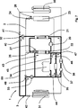
1 Ein Ausführungsbeispiel der Klimatisierungsanlage in einer Anordnung für einen Sommer- und Übergangsbetrieb mit Batteriekühlung über Chiller, 1 An embodiment of the air conditioning system in an arrangement for a summer and transient operation with battery cooling via chiller,

2 das Ausführungsbeispiel der Klimatisierungsanlage in einer Anordnung für einen Sommer- und Übergangsbetrieb mit Batteriekühlung über Kühler, 2 the embodiment of the air conditioning system in an arrangement for a summer and transitional operation with battery cooling via radiator,

3 das Ausführungsbeispiel der Klimatisierungsanlage in einer Anordnung für einen Winterbetrieb mit Umgebungswärmepumpe, 3 the embodiment of the air conditioning system in an arrangement for a winter operation with ambient heat pump,

4 das Ausführungsbeispiel der Klimatisierungsanlage in einer Anordnung für einen Winterbetrieb mit NT-Abwärme-Wärmepumpe, 4 the embodiment of the air conditioning system in an arrangement for winter operation with NT waste heat pump,

5 das Ausführungsbeispiel der Klimatisierungsanlage in einer Anordnung für einen Winterbetrieb NT-Abwärme-Wärmepumpe in serieller Verschaltung der Aggregate, 5 the embodiment of the air conditioning system in an arrangement for a winter operation NT waste heat heat pump in serial connection of the units,

6 das Ausführungsbeispiel der Klimatisierungsanlage in einer Anordnung für einen Winterbetrieb mit Direktheizung, 6 the embodiment of the air conditioning system in an arrangement for a winter operation with direct heating,

7 das Ausführungsbeispiel der Klimatisierungsanlage in einer Anordnung für einen Winter-Plug-In-Betrieb mit Aggregate -Vorheizung 7 the embodiment of the air conditioning system in an arrangement for a winter plug-in operation with aggregate preheating

8 das Ausführungsbeispiel der Klimatisierungsanlage in einer Anordnung für einen Winter-Plug-In-Betrieb mit Kabinen -Vorheizung 8th the embodiment of the air conditioning system in an arrangement for a winter plug-in operation with cabin preheating

9 das Ausführungsbeispiel der Klimatisierungsanlage in einer Anordnung für einen Sommer-Plug-In-Betrieb mit Batterieladung, 9 the embodiment of the air conditioning system in an arrangement for a summer plug-in operation with battery charging,

10 das Ausführungsbeispiel der Klimatisierungsanlage in einer Anordnung für einen Sommer-Plug-In-Betrieb mit Batterieladung bei kühler Batterie, 10 the embodiment of the air conditioning system in an arrangement for a summer plug-in operation with battery charging with a cool battery,

Die 1 bis 10 zeigen ein im Wesentlichen gleiches Ausführungsbeispiel einer Klimatisierungsanlage 1, die über einen Kältemittelkreislauf 2 und über einen Niedertemperatur (NT)-Kühlmittelkreislauf 3 verfügt. Die Klimatisierungsanlage ist dabei in beiden Kreisläufen derart mit Absperrventilen 24, 25 und 40 bis 48 ausgestattet, so dass alle Kühlmittelkreisläufe 50 bis 62 des NT-Kühlmittelkreislaufs 3 und die beiden Teilkreisläufe des Kältemittelkreislaufs 2 über Absperren und Öffnen von Ventilen schaltbar sind. Die Kühlmittelkreisläufe 50 bis 62 und Varianten des Kältemittelkreislaufs können aber auch je nach Funktionsbedarf als einzelne abgeschlossene Kreisläufe oder mit geringerer Schaltvarianz schaltbare Kreisläufe gestaltet sein.The 1 to 10 show a substantially same embodiment of an air conditioning system 1 that has a refrigerant circuit 2 and a low temperature (NT) coolant loop 3 features. The air conditioning system is so in both circuits with shut-off valves 24 . 25 and 40 to 48 equipped so that all coolant circuits 50 to 62 of the NT refrigerant circuit 3 and the two subcircuits of the refrigerant circuit 2 can be switched on shut-off and opening valves. The coolant circuits 50 to 62 And variants of the refrigerant circuit can also be designed depending on the functional requirements as a single closed circuits or with less switching variance switchable circuits.

Das Ausführungsbeispiel der Klimatisierungsanlage 1 weist einen Kältemittelkreislauf 2 auf, in dem ein elektrisch arbeitender Kältemittelverdichter 20 angeordnet ist. Stromab des Kältemittelverdichters 20 ist ein kühlmittelgekühlter Kondensator 21 vorgesehen. Stromab des Kondensators 21 verzweigt sich der Kältemittelkreislauf in einen Strang mit einem kühlmittelseitig wirkenden Verdampfer 22, der zum Wärmetausch zwischen Kältemittel und Kühlmittel vorgesehen ist, und einen Strang mit einem luftseitig wirkenden Verdampfer 23, der Luft, welche einer Fahrzeugkabine zugeführt wird kühlt. Dabei kann der luftseitige Verdampfer 23 von Frischluft und/oder von Umluft durchströmt werden. Die beiden Stränge sind stromab mit der Saugseite des Kältemittelverdichters 20 verbunden und bilden so zwei Teilkreisläufe des Kältemittelkreislaufs 2. Im Strang des luftseitigen Verdampfers 23 ist ein Absperrventil 24 und stromauf des Verdampfers 23 ein Expansionsorgan 26 angeordnet. Im Strang des kühlmittelseitigen Verdampfers 22 ist ein Absperrventil 25 und stromauf des Verdampfers 22 ein Expansionsorgan 27 angeordnet. Die beiden Teilkreisläufe des Kältemittelkreislaufs 2 sind durch eine Steuerung der Leistung des Kältemittelverdichters 20 und über die Ventile 24 bis 27 in Ihrer jeweiligen Funktionsleistung steuerbar.The embodiment of the air conditioning system 1 has a refrigerant circuit 2 in which an electrically operating refrigerant compressor 20 is arranged. Downstream of the refrigerant compressor 20 is a coolant-cooled condenser 21 intended. Downstream of the capacitor 21 the refrigerant circuit branches into a strand with a coolant side acting evaporator 22 , which is provided for the heat exchange between refrigerant and coolant, and a strand with an air side acting evaporator 23 which cools air which is supplied to a vehicle cabin. In this case, the air-side evaporator 23 be traversed by fresh air and / or circulating air. The two strands are downstream with the suction side of the refrigerant compressor 20 connected and thus form two partial circuits of the refrigerant circuit 2 , In the strand of the air-side evaporator 23 is a shut-off valve 24 and upstream of the evaporator 23 an expansion organ 26 arranged. In the strand of the coolant-side evaporator 22 is a shut-off valve 25 and upstream of the evaporator 22 an expansion organ 27 arranged. The two subcircuits of the refrigerant circuit 2 are by controlling the performance of the refrigerant compressor 20 and over the valves 24 to 27 controllable in their respective functional performance.

Der NT-Kühlmittelkreislauf 3 der Klimatisierungsanlage 1 weist einen Kühlmittelkreislauf 50 mit einem Kühler 31, dem kühlmittelseitig wirkenden Kondensator 21, dem eine Umwälzpumpe 32 zugeordnet ist, einem Elektromotor 37 und einer Leistungselektronik 36 auf. Die Leistungselektronik 36 dient der Steuerung des Elektromotors 37.The NT coolant circuit 3 the air conditioning system 1 has a coolant circuit 50 with a cooler 31 , the coolant-side condenser 21 to which a circulating pump 32 is assigned, an electric motor 37 and power electronics 36 on. The power electronics 36 serves to control the electric motor 37 ,

Der Kühlmittelkreislauf 50 weist zwischen dem Kühler 31 und der dem Kondensator 21 zugeordneten Umwälzpumpe 32 ein Ventil 40 und stromab des Ventils 40 einen Abzweig auf, in dem parallel zu Leistungselektronik 36, Elektroantriebsmotor 37 und Kühler 31 ein Kabinenwärmetauscher 30 angeordnet ist, der mittels eines Ventils 41 absperrbar ist. Es ist somit ein Kühlmittelkreislauf 52 betreibbar, der bei geschlossenem Ventil 40 den Kabinenwärmetauscher 30, das diesem zugeordnete Ventil 41, die dem Kondensator 21 zugeordnete Umwälzpumpe 32 und den Kondensator 21 aufweist. Die dem Kondensator 21 zugeordnete Umwälzpumpe 32 kann bei geöffnetem Ventil 40 Kühlmittel aus Richtung des Kühlers 31 und/oder bei geöffnetem Ventil 41 aus Richtung des Kabinenwärmetauschers zum Kondensator 21 hin fördern.The coolant circuit 50 points between the radiator 31 and the capacitor 21 associated circulation pump 32 a valve 40 and downstream of the valve 40 a branch, in which parallel to power electronics 36 , Electric drive motor 37 and coolers 31 a cabin heat exchanger 30 is arranged, by means of a valve 41 can be locked. It is thus a coolant circuit 52 operable, with the valve closed 40 the cabin heat exchanger 30 , the associated valve 41 that the capacitor 21 associated circulating pump 32 and the capacitor 21 having. The the capacitor 21 associated circulating pump 32 can when the valve is open 40 Coolant from the direction of the radiator 31 and / or with the valve open 41 from the direction of the cabin heat exchanger to the condenser 21 promote it.

Der NT-Kühlmittelkreislauf 3 weist einen in 2 gezeigten Kühlmittelkreislauf 51 auf, in dem parallel zum Kondensator 21 und der Umwälzpumpe 32 ein Dreiwegeventil 48, eine einer Antriebsbatterie 34 zugeordnete Umwälzpumpe 33, die Antriebsbatterie 34, die Leistungselektronik 36, der Elektromotor 37 und der Kühler 31 angeordnet sind. Das Dreiwegeventil 48 ist an der Saugseite der Umwälzpumpe 33 der Antriebsbatterie 34 angeschlossen, die durch Umschaltung der Eingangsseite des Dreiwegeventils 48 entweder an einem Abzweig am Kühlmittelkreislauf 50 zwischen Kühler 31 und Kondensator 21 oder am Auslass des kühlmittelseitig wirkenden Verdampfers 22 anschließbar ist. Auf der Abströmseite ist die Umwälzpumpe 33 an der Anströmseite der Antriebsbatterie 34 angeschlossen. Die Durchströmung der Antriebsbatterie 34 ist mittels eines Ventils 45 absperrbar. An der Abströmseite der Antriebsbatterie 34 ist die Zuströmseite des kühlmittelseitig wirkenden Verdampfers 22 und die mittels eines Ventils 47 absperrbare Zuströmseite von Leistungselektronik 36 und dem stromab der Leistungselektronik 36 angeordneten Elektroantriebsmotor 37 angeschlossen.The NT coolant circuit 3 has an in 2 shown coolant circuit 51 on, in parallel to the capacitor 21 and the circulation pump 32 a three-way valve 48 , one of a drive battery 34 associated circulating pump 33 , the drive battery 34 , the power electronics 36 , the electric motor 37 and the radiator 31 are arranged. The three-way valve 48 is on the suction side of the circulation pump 33 the drive battery 34 connected by switching the input side of the three-way valve 48 either at a branch on the coolant circuit 50 between cooler 31 and capacitor 21 or at the outlet of the evaporator acting on the coolant side 22 is connectable. On the downstream side is the circulation pump 33 on the upstream side of the drive battery 34 connected. The flow through the drive battery 34 is by means of a valve 45 shut off. At the downstream side of the drive battery 34 is the upstream side of the evaporator acting on the coolant side 22 and by means of a valve 47 Lockable upstream side of power electronics 36 and the downstream of the power electronics 36 arranged electric drive motor 37 connected.

Eine mittels eines Ventils 43 absperrbare Überströmleitung von der Abströmseite der Umwälzpumpe 33 zur Abströmseite des kühlmittelseitigen Verdampfers 22 kann diesen mittels der Umwälzpumpe rückwärts durchströmt beaufschlagen.One by means of a valve 43 Lockable overflow line from the downstream side of the circulation pump 33 to the downstream side of the coolant-side evaporator 22 can apply these flows backwards through the circulation pump.

Eine Leitung, in der ein von Kühlmittel durchströmbarer On-Board-Lader 35 angeordnet ist, verbindet als Abzweig an der Abströmseite der Antriebsbatterie 34 und den dort angeschlossenen Leitungen zu Verdampfer 22 und zur Leistungselektronik 36 mit einer Überströmleitung, die vom Einlass der Antriebsbatterie 34 hin zu einer Einmündung an einer Leitung von Elektromotor 37 zum Kühler 31 im Kühlmittelkreislauf 50 führt. Dabei ist die Überströmleitung vom Einlass der Antriebsbatterie 34 zur Einmündung zwischen Elektromotor 37 und Kühler 31 vor dem Anschluß des On-Board-Laders mittels eines Ventils 44 absperrbar. Die Leitung zum On-Board-Lader 35 ist mittels eines Ventils 46 absperrbar.A line in which a coolant-flowable on-board loader 35 is arranged, connects as a branch on the downstream side of the drive battery 34 and the connected lines to evaporator 22 and to power electronics 36 with an overflow line coming from the inlet of the drive battery 34 towards a junction with a line of electric motor 37 to the radiator 31 in the coolant circuit 50 leads. The overflow line is from the inlet of the drive battery 34 to the junction between the electric motor 37 and coolers 31 before connecting the on-board charger by means of a valve 44 shut off. The line to the on-board loader 35 is by means of a valve 46 shut off.

All die voranstehend oder nachfolgend beschriebenen Kreislaufvarianten können so wie im beschriebenen Ausführungsbeispiel als komplex schaltbarer, flexibler Gesamtkreislauf gestaltet sein. Ebenso ist es möglich, die für die einzelnen Funktionen notwendigen Kühlmittelkreisläufe oder Kältemittelkreisläufe als geschlossene Einzelkreisläufe oder je nach Funktionsbedarf als weniger komplex schaltbare Teilkreisläufe des hier beschriebenen Systems zu gestalten.All the circuit variants described above or below can be designed as a complex switchable, flexible overall circuit as in the described embodiment. Likewise, it is possible to design the necessary for the individual functions coolant circuits or refrigerant circuits as closed individual circuits or depending on functional requirements as less complex switchable partial circuits of the system described here.

In 1 ist die Klimatisierungsanlage 1 in einer zu einem Sommerbetriebsfall gehörenden Anordnung dargestellt, in dem die Fahrzeugkabine und die Antriebsbatterie 34 zu kühlen sind. Dabei weist der betriebene Kältemittelkreislauf den fördernden Kältemittelkompressor 20 und stromab den kühlmittelgekühlten Kondensator 21 auf. Um Fahrzeugkabine und Antriebsbatterie 34 ausreichend zu Kühlen sind stromab des Kondensators 21 der kühlmittelseitig wirkende Verdampfer 22 und der luftseitig wirkende Verdampfer 23 parallel im Kältemittelkreislauf angeordnet und durchströmt. Die zugehörigen Absperrventile 24 und 25 sind geöffnet. Stromauf der Verdampfer 22 und 23 wird das Kältemittel an jeweils zugeordneten Expansionsventilen 26 und 27 entspannt. Eine Regelung der Beaufschlagungen der beiden Verdampfer 22 und 23 mit Kältemittel kann mittels des Ventils 24, 25, einer Steuerung der Förderleistung des Kältemittelkompressors 20, des Expansionsventils 26 und/oder des Expansionsventils 27 in einzelner oder gemeinsamer Regelung erfolgen.In 1 is the air conditioning system 1 in an arrangement belonging to a summer operation case in which the vehicle cabin and the drive battery 34 to cool. In this case, the operated refrigerant circuit has the promotional refrigerant compressor 20 and downstream of the coolant-cooled condenser 21 on. To vehicle cabin and drive battery 34 Cool enough to be downstream of the condenser 21 the coolant side acting evaporator 22 and the air-side evaporator 23 arranged and flows parallel in the refrigerant circuit. The associated shut-off valves 24 and 25 are opened. Upstream of the evaporator 22 and 23 is the refrigerant to each associated expansion valves 26 and 27 relaxed. A regulation of the impingements of the two evaporators 22 and 23 with refrigerant can by means of the valve 24 . 25 , a control of the capacity of the refrigerant compressor 20 , the expansion valve 26 and / or the expansion valve 27 in single or common regulation.

Kühlmittelseitig ist der Verdampfer 22 in einen Kühlmittelkreislauf 54 integriert, der den Verdampfer 22, die Umwälzpumpe 33 und die Antriebsbatterie 34 aufweist. Die Schaltung zur Begrenzung dieses Kühlmittelkreislaufs 54 gegen die weiteren Aggregate des NT-Kühlmittelkreislaufs 3 erfolgt vornehmlich durch eine Schaltstellung des Dreiwegeventils 48, das die Ansaugseite der Umwälzpumpe 33 mit der Abströmseite des kühlmittelseitigen Verdampfers 22 verbindet und eine Verbindungsleitung zu NT-Kühler und Kondensator 21 hin absperrt. Weitere Ventile 44, 46 und 47, in weiteren Verbindungsleitungen zum restlichen NT-Kühlmittelkreislauf hin, können zum Vermeiden von Mischvorgängen und somit zur Leistungsverbesserung ebenso geschlossen sein. Durch die Kühlung der Antriebsbatterie 34 mittels des kühlmittelseitig wirkenden Verdampfers 22 und des zugehörigen Kältemittelkreislaufs ist eine besonders leistungsstarke Kühlung der Antriebsbatterie 34 mittels des Kältekreislaufs 2 möglich. Die Kältemittelbeaufschlagung des Verdampfers 22 wird im Hinblick auf die erforderliche Kühlleistung an der Antriebsbatterie 34 gesteuert.Coolant side is the evaporator 22 in a coolant circuit 54 integrated, the evaporator 22 , the circulation pump 33 and the drive battery 34 having. The circuit for limiting this coolant circuit 54 against the other aggregates of the NT coolant circuit 3 takes place primarily by a switching position of the three-way valve 48 , which is the suction side of the circulation pump 33 with the downstream side of the coolant side evaporator 22 connects and a connecting line to NT cooler and condenser 21 shut off. Other valves 44 . 46 and 47 , in other connecting lines to the rest of the NT refrigerant circuit, can be closed to avoid mixing operations and thus to improve performance as well. By cooling the drive battery 34 by means of the coolant side acting evaporator 22 and the associated refrigerant circuit is a particularly powerful cooling of the drive battery 34 by means of the refrigeration cycle 2 possible. The refrigerant charge of the evaporator 22 is in view of the required cooling capacity on the drive battery 34 controlled.

Der luftseitig wirkende Verdampfer 23 ist auch im Kältemittelkreislauf 2 mit einem Kältemittelstrom beaufschlagt und kühlt Frischluft und/oder Umluft, welche der Fahrzeugkabine zugeführt wird. Nach dem Verdampfer 23 kann der diesen durchströmende Luftstrom ganz oder teilweise durch einen im Luftstrom stromab des Verdampfers 23 angeordneten Kabinenwärmetauscher 30 zum Einstellen einer Komforttemperatur aufgewärmt werden. Dafür ist der Kabinenwärmetauscher 30 in einem Kühlmittelkreislauf 52 angeordnet, in dem bei Betrieb der Kältemittelanlage der Kondensator 21 mit zugeordneter Umwälzpumpe 32 und der Kabinenwärmetauscher 30 angeordnet sind. Die Beaufschlagung des Kabinenwärmetauschers 30 mit Kühlmittel kann über das zugeordnete Ventil 41 steuerbar sein.The air side evaporator 23 is also in the refrigerant circuit 2 acted upon by a refrigerant flow and cools fresh air and / or circulating air, which is supplied to the vehicle cabin. After the evaporator 23 the air flow flowing through it can be wholly or partly through an air flow downstream of the evaporator 23 arranged cabin heat exchanger 30 to be warmed up for setting a comfort temperature. This is the cabin heat exchanger 30 in a coolant circuit 52 arranged in which in operation of the refrigerant system, the condenser 21 with assigned circulating pump 32 and the cabin heat exchanger 30 are arranged. The admission of the cabin heat exchanger 30 with coolant can be via the associated valve 41 be controllable.

Der kühlmitteldurchströmte Kondensator 21 ist zur Bereitstellung der Kühlleistung für Antriebsbatterie 34 und Kabinenluftstrom am Verdampfer 23 in einem Kühlmittelkreislauf 50 angeordnet, in dem im Wesentlichen der Kondensator 21, die ihm zugeordnete Umwälzpumpe 32 und der Kühler 31 angeordnet sind. Am Kühler 31 wird die am Kondensator 21 abgeführte Wärme an einen Kühlluftstrom abgegeben werden. Da in diesem Kühlluftstrom unter Verzicht auf einen luftseitig wirkenden Kondensator nur der Kühler 31 angeorndet ist, kann dieser eine höhere Kühlleistung umsetzen.The coolant flowed through condenser 21 is to provide the cooling power for traction battery 34 and cabin airflow at the evaporator 23 in a coolant circuit 50 arranged, in which essentially the capacitor 21 , the circulation pump assigned to him 32 and the radiator 31 are arranged. On the radiator 31 becomes the at the condenser 21 dissipated heat to a cooling air flow be delivered. Since in this cooling air flow waiving a condenser acting on the air side, only the radiator 31 angeorndet, this can implement a higher cooling capacity.

Im Kühlmittelkreislauf 50 sind darüber hinaus noch ein elektrischer Antriebsmotor 37 und eine zugehörige Leistungselektronik 36 angeordnet, die ebenso wie der Kondensator 21 mittels des über den Kühler 31 geführten Kühlmittelstroms gekühlt werden.In the coolant circuit 50 are also still an electric drive motor 37 and associated power electronics 36 arranged as well as the capacitor 21 by means of the over the radiator 31 cooled coolant flow can be cooled.

Zusammenfassend bietet eine Klimatisierungsanlage 1 mit den in 1 dargestellten Kühlmittel- und Kältemittelkreisläufen eine effektive und besonders leistungsfähige mittelbare Kühlung der Antriebsbatterie 34 über den als Chiller arbeitenden Kältemittelkreislauf 2. Dabei erfolgt die Wärmeabfuhr der am kühlmittelseitigen Verdampfer 22 aus dem Kühlmittelkreislauf 54 aufgenommenen Abwärme der Antriebsbatterie 34 sowie der der Kabinenluft am luftseitigen Verdampfer 23 abgeführten Wärme über den Kondensator 21 an einen Kühlmittelkreislauf 50, der des Weiteren die Abwärme des Elektromotors 37 und dessen Leistungselektronik 36 aufnimmt und über den Kühler 31 an die Umgebung abführt. Eine erneute Aufwärmung der am luftseitigen Verdampfer 23 abgekühlten Kabinenluft erfolgt über den im Nebenstrom zum Kühler 31 angeordneten Kabinenwärmetauscher 30. Diese Funktion ist insbesondere während einer Übergangszeit und in einem sommerlichen Lastfall benötigter Betrieb.In summary, offers an air conditioning system 1 with the in 1 shown refrigerant and refrigerant circuits an effective and very powerful indirect cooling of the drive battery 34 over the chiller working refrigerant circuit 2 , In this case, the heat dissipation takes place at the evaporator on the coolant side 22 from the coolant circuit 54 absorbed waste heat of the drive battery 34 as well as the cabin air on the air side evaporator 23 dissipated heat through the capacitor 21 to a coolant circuit 50 , the further the waste heat of the electric motor 37 and its power electronics 36 picks up and over the radiator 31 dissipates to the environment. Another reheating of the air-side evaporator 23 Cooled cabin air takes place via the bypass flow to the radiator 31 arranged cabin heat exchanger 30 , This function is particularly needed during a transitional period and in a summer load case operation.

2 zeigt eine Anordnung der Klimatisierungsanlage 1 die ähnlich der Anordnung gemäß 1 insbesondere für einen Lastfall der Übergangszeit oder des Sommers geeignet ist. Dabei ist diese Anordnung besonders für Betriebszustände geeignet, in denen die thermische Last an der Antriebsbatterie 34 geringer ist. Dadurch kann die Antriebsbatterie 34 in einem Kühlmittelkreislauf 51 mit Hilfe der Umwälzpumpe 33 direkt über den Kühler gekühlt werden, so dass zum Betrieb des Kältemittelkreislaufs 2, der mittels des Kompressors 20, des Kondensators 21, des Expansionsventils 26 sowie des luftseitigen Verdampfers 23 nur die Kabinenluft kühlt, erheblich weniger Energieaufwand benötigt wird. 2 shows an arrangement of the air conditioning system 1 the similar to the arrangement according to 1 particularly suitable for a load case of transitional or summer. In this case, this arrangement is particularly suitable for operating conditions in which the thermal load on the drive battery 34 is lower. This allows the drive battery 34 in a coolant circuit 51 with the help of the circulation pump 33 be cooled directly over the radiator, allowing for operation of the refrigerant circuit 2 that by means of the compressor 20 , the capacitor 21 , the expansion valve 26 and the airside evaporator 23 only the cabin air cools, significantly less energy is needed.

Bei der Klimatisierungsanlage 1 ist in dieser Anordnung gemäß der 2 ein Kühlmittelkreislauf 51 zur Kühlung der Antriebsbatterie 34 mit dem Dreiwegeventil 48, das in dieser Anordnung die Abströmseite des Kühlers 31 mit der Ansaugseite der Umwälzpumpe 33 verbindet, der Umwälzpumpe 33, der Antriebsbatterie 34, dem geöffneten abströmseitigen Ventil 45 der Antriebsbatterie 34, dem geöffneten Ventil 47, der Leistungselektronik 36 und dem zugehörigen Elektromotor 37, dem Kühler 31 und dem geöffneten Ventil 42 auf der Abströmseite des Kühlers 31 vorgesehen. Dabei ist über das Dreiwegeventil 48 und das Ventil 43 der kühlmittelseitige Verdampfer 22 vom Kühlmittelkreislauf 51 abgesperrt. Der On-Board-Lader 35 ist durch die Ventile 46 und 44 vom Kühlmittelkreislauf abgesperrt. Die Umwälzpumpe 33 wird in ihrer Förderleistung insbesondere auf die Kühlanforderung der Antriebsbatterie 34 abgestimmt. Des Weiteren können Kühlanforderungen der Leistungselektronik 36 und des Elektromotors 37 zur Ansteuerung der Umwälzpumpe 33 herangezogen werden.In the air conditioning system 1 is in this arrangement according to the 2 a coolant circuit 51 for cooling the drive battery 34 with the three-way valve 48 , in this arrangement, the downstream side of the radiator 31 with the suction side of the circulation pump 33 connects, the circulation pump 33 , the drive battery 34 , the open downstream valve 45 the drive battery 34 , the open valve 47 , the power electronics 36 and the associated electric motor 37 , the cooler 31 and the open valve 42 on the downstream side of the radiator 31 intended. It is about the three-way valve 48 and the valve 43 the coolant-side evaporator 22 from the coolant circuit 51 shut off. The on-board loader 35 is through the valves 46 and 44 shut off from the coolant circuit. The circulation pump 33 is in their capacity especially on the cooling requirement of the drive battery 34 Voted. Furthermore, cooling requirements of the power electronics 36 and the electric motor 37 for controlling the circulation pump 33 be used.

Im Nebenstrom zu Umwälzpumpe 33 und Antriebsbatterie 34 ist bei der in 2 gezeigten Anordnung der Kondensator 21 mit zugeordneter Umwälzpumpe 32 angeordnet. Das geöffnete kühlerseitige Ventil 40, die Umwälzpumpe 32, der Kondensator 21, die Leistungselektronik 36, der Elektromotor 37, der Kühler 31 und das geöffnete abströmseitige Ventil 42 des Kühlers 31 bilden somit einen eigenen Kühlmittelkreislauf 50. Von der Leistungselektronik 36, über Elektromotor 37 und Kühler 31 weisen die Kühlmittelkreisläufe 50 und 51 einen gemeinsamen Strömungspfad auf, in dem sich die Kühlmittelströme der beiden Kühlmittelkreisläufe 50 und 51 vermischen. Kühlanforderungen der Leistungselektronik 36 und des Elektromotors 37 können somit sowohl durch Ansteuerung der Umwälzpumpe 33 der Antriebsbatterie 34, als auch durch Ansteuerung der Umwälzpumpe 32 des Kondensators 21 ausgeglichen werden.In the secondary flow to circulating pump 33 and drive battery 34 is at the in 2 shown arrangement of the capacitor 21 with assigned circulating pump 32 arranged. The open radiator-side valve 40 , the circulation pump 32 , the capacitor 21 , the power electronics 36 , the electric motor 37 , the cooler 31 and the open downstream valve 42 the radiator 31 thus form a separate coolant circuit 50 , From the power electronics 36 , via electric motor 37 and coolers 31 have the coolant circuits 50 and 51 a common flow path in which the coolant flows of the two coolant circuits 50 and 51 mix. Cooling requirements of power electronics 36 and the electric motor 37 can thus both by controlling the circulation pump 33 the drive battery 34 , as well as by controlling the circulation pump 32 of the capacitor 21 be compensated.

Im Nebenstrom zu Leistungselektronik 36, Elektromotor 37 und Kühler 31 ist an einem Strömungspfad mit der Umwälzpumpe 32 und dem Kondensator 21 der Kabinenwärmetauscher 30 angeschlossen, der die vom Verdampfer 23 gekühlte Kabinenluft nach Komfortanforderungen mindestens teilweise aufheizt. Dabei wird die dem Kabinenluftstrom zugeführte Wärme bei einer luftgeregelten Klimatisierungsanlage durch Mischung eines erhitzten Teils des Kabinenluftstroms mit einem kühlen, den Kabinenwärmetauscher 30 umströmenden, Teil des Kabinenluftstroms geregelt. Des Weiteren kann die dem Kabinenluftstrom zugeführte Wärme durch Ansteuerung des dem Kabinenwärmetauscher 30 zugeordneten Ventils 41 erfolgen. Dies kann bei Erhitzung des vollständigen Kabinenluftstroms mittels des Kabinenwärmetauschers 30 oder ergänzend zu oben erläuterter Mischung von Teilluftströmen des Kabinenluftstroms erfolgen.In the sidestream to power electronics 36 , Electric motor 37 and coolers 31 is at a flow path with the circulation pump 32 and the capacitor 21 the cabin heat exchanger 30 connected to the evaporator 23 cooled cabin air after comfort requirements at least partially heats. In this case, the heat supplied to the cabin air flow in an air-controlled air conditioning system by mixing a heated part of the cabin air flow with a cool, the cabin heat exchanger 30 flowing around, part of the cabin air flow regulated. Furthermore, the heat supplied to the cabin air flow by controlling the cabin heat exchanger 30 associated valve 41 respectively. This can be done by heating the full cabin airflow by means of the cabin heat exchanger 30 or in addition to the above-explained mixture of partial air flows of the cabin air flow.

3 zeigt eine Anordnung der Klimatisierungsanlage 1 für eine besonders effektive Aufwärmung der Fahrzeugkabine unter winterlichen Bedingungen. Dabei ist der Kältemittelkreislauf 2, mit dem Kältemittelverdichter 20, dem Expansionsventil 27 und dem kühlmittelseitigen Verdampfer 22 als Wärmepumpe betreibbar, wobei einem Kühlmittelkreislauf 55, der die Umwälzpumpe 33, den kühlmittelseitigen Verdampfer 22, die Leistungselektronik 36, den Elektromotor 37 und den Kühler 31 aufweist, Wärme entzogen wird, die den elektrischen Bauteilen Leistungselektronik 36 und Elektromotor 37 und/oder über den Kühler 31 der Umgebung entzogen wird. Dabei kann die an Leistungselektronik 36 und Elektromotor 37 entzogene Wärme entweder eine Betriebsabwärme dieser Bauteile oder Speicherwärme sein, die durch Aufheizung der Bauteile bei Anschluß des Fahrzeugs an einen elektrischen Versorgungsanschluss beispielsweise bei oder nach dem Laden und Ansteuerung von Leistungselektronik 36 und Elektromotor 37 mit Blindleistung erzeugt wurde. 3 shows an arrangement of the air conditioning system 1 for a particularly effective warming up of the vehicle cabin in wintry conditions. Here is the refrigerant circuit 2 , with the refrigerant compressor 20 , the expansion valve 27 and the coolant side evaporator 22 operated as a heat pump, with a coolant circuit 55 , the circulation pump 33 , the coolant-side evaporator 22 , the power electronics 36 , the electric motor 37 and the radiator 31 having, Heat is extracted, which is the electrical components power electronics 36 and electric motor 37 and / or over the radiator 31 the environment is withdrawn. It can be the power electronics 36 and electric motor 37 extracted heat either be a waste heat of these components or storage heat, by heating the components when connecting the vehicle to an electrical supply connection, for example, during or after charging and control of power electronics 36 and electric motor 37 generated with reactive power.

Der Kühlmittelkreislauf 55 weist die das Kühlmittel umlaufend fördernde Umwälzpumpe 33 auf, welche das Kühlmittel über das geöffnete Ventil 43 dem Verdampfer 22 zuführt. Die Antriebsbatterie 34, der On-Board-Lader 35 und eine Überströmleitung sind durch die geschlossenen Ventile 44, 45 und 46 gegen eine Durchströmung abgesperrt. Nach dem Verdampfer 22, in dem Wärme an den Kältemittelkreislauf 2 abgegeben wird, ist im Kühlmittelkreislauf 55 das geöffnete Ventil 47, die Leistungselektronik 36, der Elektromotor 37 der Kühler 31 und das geöffnete Ventil 42 angeschlossen, das mit dem Dreiwegeventil 48 verbunden ist, das das Kühlmittel wieder dem Einlass der Umwälzpumpe 33 zuführt. Der Kühlmittelkreislauf 55 ist über das geschlossene Ventil 40 in der Verbindung vom Auslass des Kühlers 31 und Einlass der Umwälzpumpe 32 gegen den Kühlmittelkreislauf 32 gesperrt.The coolant circuit 55 has the coolant circulating promotional circulating pump 33 on which the coolant through the open valve 43 the evaporator 22 supplies. The drive battery 34 , the on-board loader 35 and an overflow line are through the closed valves 44 . 45 and 46 shut off against a flow. After the evaporator 22 , in which heat to the refrigerant circuit 2 is discharged, is in the coolant circuit 55 the opened valve 47 , the power electronics 36 , the electric motor 37 the cooler 31 and the open valve 42 connected to the three-way valve 48 connected, which returns the coolant to the inlet of the circulation pump 33 supplies. The coolant circuit 55 is over the closed valve 40 in the connection from the outlet of the radiator 31 and inlet of the circulation pump 32 against the coolant circuit 32 blocked.

Besondere Heizeffizienz wird dabei dadurch erreicht, dass Leistungselektronik 36 und Elektromotor 37 bei niedrigen Temperaturen durch die Wärmepumpe gekühlt werden. Einerseits wird die Abwärme von Leistungselektronik 36 und Elektromotor 37 mittels der Wärmepumpe zum Beheizen genutzt, andererseits werden die Leistungselektronik 36 und Elektromotor 37 auf niedriger Temperatur gehalten, so dass eine Wärmeabgabe an die Umgebung minimiert ist. Ist die Außentemperatur dabei sehr niedrig, kann der Kühler 31 vereisen, wodurch er isoliert wird und die an Leistungselektronik 36 und Elektromotor 37 entstehende Wärme nicht über den Kühler an die Umgebung abgeführt, sondern dem Verdampfer 22 der Wärmepumpe zugeführt wird. Durch Absenkung des Temperaturniveaus des Kühlmittels kann der Wärmeverlust über den (vereisten) Kühler komplett unterbunden werden. In günstigen Betriebsfällen kann das Oberflächentemperaturniveau der Leistungselektronik und des Elektromotors unterhalb des Umgebungstemperaturniveaus liegen, so dass diese Komponenten keine Abwärme verlieren, sondern Umgebungswärme aufnehmen.Special heating efficiency is thereby achieved that power electronics 36 and electric motor 37 be cooled by the heat pump at low temperatures. On the one hand, the waste heat from power electronics 36 and electric motor 37 used by the heat pump for heating, on the other hand, the power electronics 36 and electric motor 37 kept at a low temperature, so that a heat transfer to the environment is minimized. If the outside temperature is very low, the cooler can 31 freeze, which isolates it and the power electronics 36 and electric motor 37 generated heat is not dissipated via the radiator to the environment, but the evaporator 22 the heat pump is supplied. By lowering the temperature level of the coolant, the heat loss through the (iced) radiator can be completely prevented. In favorable operating conditions, the surface temperature level of the power electronics and the electric motor may be below the ambient temperature level, so that these components lose no waste heat, but absorb ambient heat.

Der Kondensator 21 des Kältemittelkreislaufs 2 gibt die Wärme an einen Kühlmittelkreislauf 52 ab, der die Umwälzpumpe 32, den Kondensator 21, den Kabinenwärmetauscher 30 und das geöffnete Ventil 41 aufweist, wobei mittels des Kabinenwärmetauschers 30 die Wärme dem Kabinenluftstrom zuführbar ist und so die Kabine aufgeheizt wird. Der Kühlmittelkreislauf 52 ist mittels des Ventils 40 gegen den restlichen Teil des NT-Kühlmittelkreislaufs 3 gesperrt.The capacitor 21 of the refrigerant circuit 2 gives the heat to a coolant circuit 52 off, the circulation pump 32 , the condenser 21 , the cabin heat exchanger 30 and the open valve 41 having, by means of the cabin heat exchanger 30 the heat can be supplied to the cabin air flow and thus the cabin is heated up. The coolant circuit 52 is by means of the valve 40 against the remaining part of the NT coolant circuit 3 blocked.

4 zeigt das Ausführungsbeispiel der Klimatisierungsanlage in einer Anordnung für einen Winterbetrieb, bei dem die Fahrzeugkabine mittels eines als Wärmepumpe arbeitenden Kältemittelkreislaufs 2 beheizt wird. Dabei wird die Wärme an Aggregaten aufgenommen, die vor Fahrtantritt vorgeheizt sind und als Wärmespeicher dienen oder an denen im Fahrbetrieb Abwärme entsteht. Dabei ist eine besondere Effektivität der Heizfunktion gegeben, da die Wärme durch die Wärmepumpenfunktion bei niedriger Temperatur aufgenommen werden kann, so dass die Wärme abgebenden Aggregate auf niedriger Temperatur gehalten werden können und dadurch bedeutend weniger Wärme ungenutzt an die Umgebung abgeben. 4 shows the embodiment of the air conditioning system in an arrangement for a winter operation, in which the vehicle cabin by means of a working as a heat pump refrigerant circuit 2 is heated. The heat is absorbed in units that are preheated before driving and serve as a heat storage or where heat is generated during driving. In this case, a particular effectiveness of the heating function is given, since the heat can be absorbed by the heat pump function at low temperature, so that the heat-emitting aggregates can be kept at low temperature and thus emit significantly less heat unused to the environment.

Der Kältemittelkreislauf 2 weist den elektrischen Kältemittelverdichter 20 auf, der das Kältemittel verdichtet, erhitzt und dem Kondensator 21 zuführt. Der Kondensator 21 gibt die Wärme an den Kühlmittelkreislauf 52 ab, der den Kondensator 21, den Kabinenwärmetauscher 30, das dem Kabinenwärmetauscher 30 zugeordnete und geöffnete Ventil 41 und die dem Kondensator 21 zugeordnete Umwälzpumpe 32 aufweist. Über den Kabinenwärmetauscher 30 wird die dem Fahrzeuginnenraum zugeführte Luft aufgeheizt. Der Kühlmittelkreislauf 52 ist mittels des Ventils 40 gegen den restlichen Teil des NT-Kühlmittelkreislaufs 3 gesperrt.The refrigerant circuit 2 has the electric refrigerant compressor 20 on, which compresses the refrigerant, heats and the condenser 21 supplies. The capacitor 21 gives the heat to the coolant circuit 52 off, the capacitor 21 , the cabin heat exchanger 30 that the cabin heat exchanger 30 assigned and opened valve 41 and the capacitor 21 associated circulating pump 32 having. About the cabin heat exchanger 30 the air supplied to the vehicle interior is heated. The coolant circuit 52 is by means of the valve 40 against the remaining part of the NT coolant circuit 3 blocked.

Nach dem Kondensator 21 sind der kühlmittelseitige Verdampfer 22 und der luftseitige Verdampfer 23 parallel angeschlossen und durchströmt. Über die Ventile 24 und 25 kann die Beaufschlagung der beiden Verdampfer 22 und 23 gesteuert werden. Über die Expansionsventile 26 und 27 wird die Kälteleistung der Verdampfer 22 und 23 geregelt.After the capacitor 21 are the coolant-side evaporator 22 and the airside evaporator 23 connected in parallel and flows through. About the valves 24 and 25 can be the admission of the two evaporators 22 and 23 to be controlled. About the expansion valves 26 and 27 the cooling capacity of the evaporator 22 and 23 regulated.

Die beiden Verdampfer 22 und 23 nehmen im Wärmepumpenbetrieb des Kältemittelkreislaufs 2 Wärme auf, die am Kondensator 21 zur Beheizung des Fahrzeuginnenraums mittels des Kabinenwärmetauschers 30 an den Kühlmittelkreislauf 52 abgegeben wird. Dabei nimmt der luftseitig wirkende Verdampfer 30 Wärme aus der dem Innenraum zugeführten Luft auf, wobei insbesondere bei Umluftbetrieb besonders viel Wärme in der dem Innenraum zugeführten Luft zur Verfügung steht und diese durch Abkühlung am Verdampfer 23 getrocknet werden kann. Durch diese Trocknung kann ein besonders hoher Umluftanteil verwendet werden. Im Mischluftbetrieb ist es zur besonders effektiven Trocknung thermisch besonders effektiv und dadurch besonders vorteilhaft, wenn kühle Außenluft erst nach der Abkühlung und Trocknung der Umluft mittels des Verdampfers 23 zu dieser zugemischt wird. Dadurch ist ein höheres Temperaturniveau zur Wärmeaufnahme im Verdampfer 23 und somit eine höhere Wärmeaufnahme im Verdampfer 23, sowie eine effektivere Trocknung der Umluft möglich.The two evaporators 22 and 23 take in heat pump operation of the refrigerant circuit 2 Heat up, on the condenser 21 for heating the vehicle interior by means of the cabin heat exchanger 30 to the coolant circuit 52 is delivered. It takes the air-side evaporator 30 Heat from the air supplied to the interior, in particular in recirculation mode particularly much heat in the air supplied to the interior is available and this by cooling the evaporator 23 can be dried. By this drying, a particularly high proportion of recirculated air can be used. In mixed air operation, it is particularly effective for particularly effective drying and thus particularly advantageous if cool outside air only after the Cooling and drying of the circulating air by means of the evaporator 23 is added to this. This is a higher temperature level for heat absorption in the evaporator 23 and thus a higher heat absorption in the evaporator 23 , As well as a more effective drying of the circulating air possible.

Der kühlmittelseitig wirkende Verdampfer 22 entzieht einem Kühlmittelkreislauf 56 Wärme. Dieser Kühlmittelkreislauf 56 weist die Umwälzpumpe 33 auf, die einlassseitig über das Dreiwegeventil 48 mit der Auslassseite des Verdampfers 22 verbunden ist und das Kühlmittel über Antriebsbatterie 34, Elektromotor 37 und Leistungselektronik 36 fördert, welche als Wärmequellen fungieren. Dabei können diese Aggregate je nach Anschlussmöglichkeiten und Temperaturniveaus in Reihe oder parallel durchströmt werden. Im Kühlmittelkreislauf 56 ist die Antriebsbatterie 34 parallel zu den miteinander in Reihe durchströmten Elektromotor 37 und Leistungselektronik 36 angeschlossen. Dazu sind das Ventil der Antriebsbatterie 34, das Ventil 44 Überströmleitung von der Einlassseite der Antriebsbatterie 34 zum Elektromotor 37 und Leistungselektronik und das Ventil 47 zwischen Verdampfer 22 beziehungsweise Abströmseite der Antriebsbatterie 34 und der Leistungselektronik 36 geöffnet und das dem On-Board-Lader 35 zugeordnete Ventil 47 gesperrt. Die Kühlmittelströme, welche die Antriebsbatterie 34, den Elektromotor 37 und die Leistungselektronik 36 durchströmen, werden zur Wärmeabgabe dem Verdampfer 22 zugeführt.The coolant side evaporator 22 withdraws a coolant circuit 56 Warmth. This coolant circuit 56 has the circulation pump 33 on, the inlet side via the three-way valve 48 with the outlet side of the evaporator 22 is connected and the coolant via drive battery 34 , Electric motor 37 and power electronics 36 promotes which act as heat sources. These units can be flowed through in series or in parallel, depending on the connection options and temperature levels. In the coolant circuit 56 is the drive battery 34 parallel to the flow through each other in series electric motor 37 and power electronics 36 connected. These are the valve of the drive battery 34 , the valve 44 Overflow line from the inlet side of the drive battery 34 to the electric motor 37 and power electronics and the valve 47 between evaporator 22 or downstream side of the drive battery 34 and the power electronics 36 open and that the on-board loader 35 associated valve 47 blocked. The coolant flows which the drive battery 34 , the electric motor 37 and the power electronics 36 flow through, are used to heat the evaporator 22 fed.

5 zeigt das Ausführungsbeispiel der Klimatisierungsanlage in einer Anordnung für einen Winterbetrieb mit Niedertemperatur-Abwärme-Wärmepumpe und serieller Verschaltung der Aggregate. Die Anordnung, der Betriebsfall und die Funktion entsprechen im Wesentlichen der Anordnung und Funktion der Klimatisierungsanlage 1, die in 4 dargestellt ist, so dass die obenstehende Beschreibung bis auf die im Folgenden beschriebenen Unterschiede auch für die hier gezeigte Anordnung des Ausführungsbeispiels gilt. 5 shows the embodiment of the air conditioning system in an arrangement for a winter operation with low-temperature waste heat heat pump and serial connection of the units. The arrangement, the operating case and the function essentially correspond to the arrangement and function of the air conditioning system 1 , in the 4 is shown, so that the above description applies to the differences described below also for the arrangement of the embodiment shown here.

In der in 5 dargestellten Anordnung ist zusätzlich zu den bereits beschriebenen Bauteilen eine mittels eines Ventils 49 absperrbare Überströmleitung vorgesehen, welche die Auslassseite der Antriebsbatterie 34 mit dem Elektromotor 37 und der Leistungselektronik 36 verbindet. Der On-Board-Lader 35 kann beispielsweise aus baulichen Gegebenheiten in der Überströmleitung angeordnet sein. Die Überströmleitung ist gegen die Einlassseite des Verdampfers 22 gesperrt, was in der vorliegenden Ausführung durch die geschlossenen Ventile 45 und 46 erfolgt. Dadurch erfolgt im Gegensatz zu der Anordnung der 4 eine serielle Durchströmung der Wärme abgebenden Aggregate Antriebsbatterie 34, Elektromotor 37 und Leistungselektronik 36. Dadurch können die Aggregate auf verschiedenen Temperaturniveaus arbeiten. Beispielsweise kann so eine stromauf der anderen Aggregate angeordnete Batterie gekühlt oder eine stromab der anderen Aggregate angeordnete Batterie warmgehalten werden.In the in 5 arrangement shown in addition to the components already described one by means of a valve 49 lockable overflow provided, which is the outlet side of the drive battery 34 with the electric motor 37 and the power electronics 36 combines. The on-board loader 35 can be arranged for example from structural conditions in the overflow. The overflow line is against the inlet side of the evaporator 22 locked, which in the present embodiment by the closed valves 45 and 46 he follows. As a result, in contrast to the arrangement of 4 a serial flow of heat-releasing aggregates drive battery 34 , Electric motor 37 and power electronics 36 , This allows the units to operate at different temperature levels. For example, a battery arranged upstream of the other units can be cooled or a battery arranged downstream of the other units can be kept warm.

In 6 ist das Ausführungsbeispiel der Klimatisierungsanlage in einer Anordnung für einen Winterbetrieb mit Direktheizung dargestellt, bei dem die Abwärme von Aggregaten, wie dem Elektromotor 37, der Leistungselektronik 36 und je nach Antriebslastfall und Außentemperaturen gegebenenfalls der Antriebsbatterie 34 direkt über einen Kühlmittelkreislauf 58 dem Kabinenwärmetauscher 30 zugeführt wird. Die Kälteanlage mit dem Kältemittelkreislauf 2 ist in diesem Betriebsfall abgeschaltet.In 6 the embodiment of the air conditioning system is shown in an arrangement for a winter operation with direct heating, in which the waste heat of aggregates, such as the electric motor 37 , the power electronics 36 and, depending on the drive load case and outside temperatures, if necessary, the drive battery 34 directly via a coolant circuit 58 the cabin heat exchanger 30 is supplied. The refrigeration system with the refrigerant circuit 2 is switched off in this case of operation.

Der Kühlmittelkreislauf 58 weist die Umwälzpumpe 33 auf, welche das Kühlmittel der Einlassseite der Antriebsbatterie 34 zufördert. Über das in Richtung des Verdampfers 22 geschlossenen Dreiwegeventil 48, sowie das in der Zuströmleitung ausgangsseitig der Umwälzpumpe angeordnete Ventil 43 ist die kühlmittelseitige Ausströmseite des Verdampfers 22 gegen den durchströmten Teil des NT-Kühlmittelkreislaufs gesperrt.The coolant circuit 58 has the circulation pump 33 on which the coolant of the inlet side of the drive battery 34 zufördert. About that in the direction of the evaporator 22 closed three-way valve 48 , And arranged in the inflow line on the output side of the circulation pump valve 43 is the coolant-side outflow side of the evaporator 22 locked against the perfused part of the NT coolant circuit.

Sollte eine Kühlungsanforderung der Antriebsbatterie 34 vorliegen, ist das Ventil 44 der Überströmleitung der Antriebsbatterie 34 geschlossen und die Antriebsbatterie 34 ist mit dem geöffneten ausgangsseitigen Ventil 45 und dem On-Board-Lader 35 mit dem zugehörigen geöffneten Ventil 46 als Rückströmstrecke im Kühlmittelkreislauf 58 integriert. Ein geschlossenes Ventil 47 verhindert eine Überströmung des Elektromotors 37 und der Leistungselektronik 36. In der Antriebsbatterie 34 nimmt das Kühlmittel Wärme auf. Sollte keine Kühlanforderung der Antriebsbatterie 34 vorliegen, sind die Ventile 45 in der Leitung der Batteriedurchströmung und 46 in der Rückströmleitung geschlossen und das Ventil 44 der Überströmleitung, die einen Bypass zur Antriebsbatterie 34 bildet geöffnet.Should be a cooling request of the drive battery 34 present, is the valve 44 the overflow line of the drive battery 34 closed and the drive battery 34 is with the valve open on the outlet side 45 and the on-board loader 35 with the associated open valve 46 as a return flow in the coolant circuit 58 integrated. A closed valve 47 prevents overflow of the electric motor 37 and the power electronics 36 , In the drive battery 34 the coolant absorbs heat. Should not be a cooling request of the drive battery 34 are present, the valves 45 in the line of battery flow and 46 closed in the return line and the valve 44 the overflow line, which bypasses the drive battery 34 makes open.

Von der Durchströmungsstrecke der Antriebsbatterie 34 beziehungsweise der Umströmungsleitung zum Umgehen der Antriebsbatterie 34 wird das Kühlmittel dem Elektromotor 37 und der Leistungselektronik 36 zugeführt, wo es weiter Wärme aufnimmt und dem Kabinenwärmetauscher 30 zur Aufheizung des dem Fahrzeuginnenraum zugeführten Luftstroms zugeführt wird. Auf der Abströmseite des Kabinenwärmetauschers 30 erfolgt über die geöffneten Ventile 40 und 41 die Rückströmung zum Dreiwegeventil 48 und zur Umwälzpumpe 33. Durch die ausgeschaltete Umwälzpumpe 32 oder ein zusätzliches Absperrventil ist dabei eine Durchströmung des kältemittelseitig ungenutzten Kondensators 21 verhindert. Der Kühler 31 ist durch das zugeordnete geschlossene Ventil 42 abgesperrt.From the flow path of the drive battery 34 or the bypass line for bypassing the drive battery 34 the coolant is the electric motor 37 and the power electronics 36 fed, where it continues to absorb heat and the cabin heat exchanger 30 is supplied for heating the air supplied to the vehicle interior. On the downstream side of the cabin heat exchanger 30 takes place via the open valves 40 and 41 the return flow to the three-way valve 48 and to the circulation pump 33 , Through the switched-off circulation pump 32 or an additional shut-off valve is a flow through the refrigerant side unused capacitor 21 prevented. The cooler 31 is through the associated closed valve 42 shut off.

Bei dieser Direktheizung ist besonders wenig elektrische Energie aufzuwenden, da nur der beschriebene Kühlmittelkreislauf 58 mittels der Umwälzpumpe umzuwälzen ist. In this direct heating is particularly little electrical energy to spend, since only the described coolant circuit 58 to circulate by means of the circulation pump.

7 zeigt das Ausführungsbeispiel der Klimatisierungsanlage in einer Anordnung in der im Winter eine Aggregate-Vorheizung bei angeschlossenem Ladeanschluss erfolgt. Dabei sollen die Antriebsbatterie 34 zur Verbesserung ihrer Ladekapazität und der Elektromotor 37 als Wärmespeicher zur Minimierung des Heizaufwands nach einem Fahrzeugstart aufgewärmt sein. Dies erfolgt vornehmlich dadurch, dass sich der von Kühlmittel durchströmte On-Board-Lader 35 im Ladebetrieb erwärmt, der Kältemittelkreislauf 2 im sogenannten kurzgeschlossenen Wärmepumpen-Betrieb arbeitet und so das Kühlmittel aufwärmt, wobei ein Kühlmittelkreislauf 59 die Wärme den anderen Aggregaten zuführt. Aufgrund der Verdichtungsarbeit des Kältemittelverdichters 20 nimmt das Kühlmittel am Kondensator 21 mehr Wärme auf als es Wärme an den Verdampfer 22 abgibt. Zusätzlich können Elektromotor 37 und Leistungselektronik 36 mit Blindleistung erwärmt werden und ihre Wärme zum Heizen genutzt und im Elektromotor gespeichert werden. 7 shows the embodiment of the air conditioning system in an arrangement in which an aggregate preheating in the winter with connected charging port. In this case, the drive battery 34 to improve their charging capacity and the electric motor 37 be warmed up as a heat storage to minimize the Heizaufwands after a vehicle start. This is done primarily by the fact that flows through the coolant on-board loader 35 heated during charging, the refrigerant circuit 2 operates in the so-called short-circuited heat pump operation and so the coolant warms up, with a coolant circuit 59 which supplies heat to the other aggregates. Due to the compression work of the refrigerant compressor 20 takes the coolant at the condenser 21 more heat than heat to the evaporator 22 emits. In addition, electric motor 37 and power electronics 36 be heated with reactive power and their heat used for heating and stored in the electric motor.

In diesem Betriebsfall arbeitet der Kältemittelkreislauf 2 als Zuheizer, der die elektrische Antriebsenergie des Kältemittelkompressors 20 in einem über einen zugehörigen Kühlmittelkreislauf 59 kurzgeschlossenen Wärmepumpenbetrieb im Wesentlichen in Wärmeenergie umsetzt. Dazu fördert der Kältemittelkompressor 20 das Kältemittel zum Kondensator 21, wo Wärme an den Kühlmittelkreislauf 59 abgegeben wird. Da der luftseitig wirkende Verdampfer 23 mittels des Ventils 24 abgesperrt ist, erfolgt die Rückströmung des Kältemittels über das geöffnete Ventil 25, das Expansionsventil 27 und den kühlmittelseitigen Verdampfer 22 zum Kältemittelkompressor 20. Am Verdampfer 22 kann der Kältemittelkreislauf 2 Wärme aus dem Kühlmittelkreislauf 59 aufnehmen.In this operating case, the refrigerant circuit works 2 as a heater, the electric drive power of the refrigerant compressor 20 in a via an associated coolant circuit 59 short-circuited heat pump operation essentially converts into heat energy. For this purpose, the refrigerant compressor promotes 20 the refrigerant to the condenser 21 where heat to the coolant circuit 59 is delivered. As the air side evaporator 23 by means of the valve 24 is shut off, the return flow of the refrigerant via the open valve 25 , the expansion valve 27 and the coolant side evaporator 22 to the refrigerant compressor 20 , At the evaporator 22 can the refrigerant circuit 2 Heat from the coolant circuit 59 take up.

Der Kühlmittelkreislauf weist die Umwälzpumpe 33 auf, die parallele Kühlmittelströme über die zu heizende Antriebsbatterie 34 und das auf ihrer Abströmseite angeordnete, geöffnete Ventil 45, parallel dazu über das geöffnete Ventil 44 der Überströmleitung, den heizenden On-Board-Lader 35 und dessen offenes Ventil 46, parallel zu diesen über den Elektromotor 37 und die Leistungselektronik 36 und über den parallel zu voranstehend beschriebenen parallelen Strömungswegen angeschlossenen Verdampfer 22 und das offene Ventil seiner Zuströmleitung 43. Nach diesen parallelen Strömungswegen ist der stark heizende Kondensator 21, die rückwärts durchströmte Umwälzpumpe 32 oder ein an dieser Stelle geöffnetes Überströmventil der Umwälzpumpe 22, das geöffnete Ventil 40 und das von dort zur Umwälzpumpe 33 hin geöffnete Dreiwegeventil 48 im Kühlmittelkreislauf 59 angeordnet. Der Kühler 31 ist über das zugeordnete Ventil 42 und der Kabinenwärmetauscher 30 über das Ventil 41 vom Kühlmittelkreislauf 59 abgesperrt.The coolant circuit has the circulation pump 33 on, the parallel coolant flows over the drive battery to be heated 34 and the open valve located on its downstream side 45 , parallel to it via the open valve 44 the overflow line, the heating on-board loader 35 and its open valve 46 , parallel to these via the electric motor 37 and the power electronics 36 and via the parallel to above-described parallel flow paths connected evaporator 22 and the open valve of its inflow line 43 , After these parallel flow paths is the strong heating capacitor 21 , the reverse flowed through circulation pump 32 or an overflow valve of the circulation pump opened at this point 22 , the open valve 40 and from there to the circulation pump 33 open three-way valve 48 in the coolant circuit 59 arranged. The cooler 31 is via the assigned valve 42 and the cabin heat exchanger 30 over the valve 41 from the coolant circuit 59 shut off.

Die in der 8 dargestellte Anordnung des Ausführungsbeispiels der Klimatisierungsanlage ermöglicht in einem Winter-Plug-In-Betrieb eine kombinierte Vorheizung von Aggregaten, sowie der Fahrzeugkabine. Dabei entspricht die Anordnung des Heizkreislaufs 60 insbesondere in ihrer Funktion im Wesentlichen der in 7 beschriebenen Anordnung des Heizkreislaufs 59 bis darauf, dass das Ventil 41 geöffnet ist und dadurch ein Kühlmittelstrom heizend den Kabinenwärmetauscher 30 beaufschlagt.The in the 8th illustrated arrangement of the embodiment of the air conditioning system allows in a winter plug-in operation, a combined preheating of units, and the vehicle cabin. The arrangement of the heating circuit corresponds 60 especially in their function essentially the in 7 described arrangement of the heating circuit 59 until the valve is on 41 is open and thereby a coolant flow heating the cabin heat exchanger 30 applied.

Grundsätzlich können dabei sämtliche Bauteile des Heizkreislaufs 59, wie in 7 beschrieben durchströmt werden. Alternativ kann aber auch eine Durchströmung wie in 8 dargestellt erfolgen, wobei diese auch auf den in 7 dargestellten Betriebsfall rückübertragbar ist. Dabei sind bei den parallelen Strömungswegen nach der Umwälzpumpe 33 durch Schließen des Ventils 44 der Überströmleitung nur noch die Antriebsbatterie 34 mit ihrem offenen Ventil 45 und parallel dazu das geöffnete Ventil 43 und der Verdampfer 22 parallel angeschlossen. Der On-Board-Lader 35 mit seinem offenen Ventil 46, sowie der Elektromotor 37 und die Leistungselektronik 36 werden in Reihe dazu durchströmt. Diese Anordnung des Kühlmittelkreislaufs 60 in diesem Bereich ist wie oben erwähnt alternativ auch auf den Kühlmittelkreislauf 59 zur ausschließlichen Vorheizung der Aggregate übertragbar.Basically all components of the heating circuit can be used 59 , as in 7 be flowed through described. Alternatively, however, a flow as in 8th shown, this also on the in 7 shown operating case retransmitted. Here are the parallel flow paths after the circulation pump 33 by closing the valve 44 the overflow line only the drive battery 34 with her open valve 45 and in parallel the opened valve 43 and the evaporator 22 connected in parallel. The on-board loader 35 with his open valve 46 , as well as the electric motor 37 and the power electronics 36 are flowed through in series. This arrangement of the coolant circuit 60 in this area, as mentioned above, alternatively also to the coolant circuit 59 for the exclusive preheating of the aggregates transferable.

Um bei Beheizung des Kabinenwärmetauschers 30 den im Kühlmittelkreislauf eigentlich parallel zum Kabinenwärmetauscher 30 angeordneten Kondensator 21 sicher zu durchströmen, wird dieser nicht wie im Kühlmittelkreislauf 59 entgegen der Förderrichtung der Umwälzpumpe 32 durchströmt, sondern mit angeschalteter Umwälzpumpe 32 in deren Förderrichtung durchströmt. Somit wird die am Kondensator 21 anfallende Wärme zunächst dem Kabinenwärmetauscher 30 zur Aufheizung der Fahrzeugkabine zugeführt. Das am Kabinenwärmetauscher 30 abströmende Kühlmittel strömt teils von der Umwälzpumpe 32 angesaugt erneut zum Kondensator 21 und teils von der über das Dreiwegeventil 48 angeschlossenen Umwälzpumpe 33 erneut zu den teils heizenden und teils zu beheizenden Aggregaten.To when heating the cabin heat exchanger 30 in the coolant circuit actually parallel to the cabin heat exchanger 30 arranged capacitor 21 safely to flow through, this is not like in the coolant circuit 59 contrary to the conveying direction of the circulation pump 32 flows through, but with connected circulating pump 32 flows through in the conveying direction. Thus, the on the capacitor 21 accumulating heat first the cabin heat exchanger 30 supplied for heating the vehicle cabin. The at the cabin heat exchanger 30 outflowing coolant flows partly from the circulation pump 32 sucked again to the condenser 21 and partly from the via the three-way valve 48 connected circulating pump 33 again to the partly heating and partly to be heated units.

In 9 ist eine Anordnung der Klimatisierungsanlage 1 für einen Betriebsfall gezeigt, bei dem bei höheren Außentemperaturen, also im sogenannten Sommerfall die Antriebsbatterie 34 bei angeschlossenem Ladeanschluss geladen wird. Dabei wird die Antriebsbatterie 34 und der On-Board-Lader 35 mittels eines Kühlmittelkreislaufs 61 gekühlt, der die der Antriebsbatterie 34 zugeordnete Umwälzpumpe 33, deren Einlassseite über das Dreiwegeventil 48 und das geöffnete Ventil 42 mit der Auslassseite des Kühlers 31 verbunden ist. Auf der Förderseite der Umwälzpumpe 33 ist die Antriebsbatterie 34 mit dem geöffneten Ventil 45, der On-Board-Lader 35 mit dessen offenen Ventil 46, sowie der Kühler 31 angeschlossen. Dabei ist der Verdampfer 22 über das Ventil 43 und die geschlossene Seite des Dreiwegeventils 48, die Überströmleitung mittels des zugehörige Ventils 44 und der restliche Teil des NT-Kühlmittelkreislaufs 3 mittels der geschlossenen Ventile 47 und 40 gegen eine Durchströmung abgesperrt.In 9 is an arrangement of the air conditioning system 1 shown for an operating case, in which at higher outside temperatures, so in the so-called summer case, the traction battery 34 is charged when the charging port is connected. This is the drive battery 34 and the on-board loader 35 by means of a coolant circuit 61 cooled, that of the drive battery 34 associated circulating pump 33 , its inlet side via the three-way valve 48 and the open valve 42 with the outlet side of the radiator 31 connected is. On the delivery side of the circulation pump 33 is the drive battery 34 with the valve open 45 , the on-board loader 35 with its open valve 46 , as well as the radiator 31 connected. Here is the evaporator 22 over the valve 43 and the closed side of the three-way valve 48 , the overflow line by means of the associated valve 44 and the remainder of the NT refrigerant circuit 3 by means of the closed valves 47 and 40 shut off against a flow.

Der Kühlmittelkreislauf 61 bildet in dieser Anordnung einen besonders verbrauchsarm zu betreibenden und effektiv arbeitenden Kühlmittelkreis für die sich während des Ladevorgangs erwärmende Antriebsbatterie 34 und den On-Board-Lader 35. Um einen Abtransport der an der Antriebsbatterie 34 entstehenden Wärme zu ermöglichen, ist es Vorraussetzung, dass die Außentemperatur kleiner ist, als eine maximal zulässige Temperatur der Antriebsbatterie 34.The coolant circuit 61 forms in this arrangement a particularly fuel-efficient and effectively operating coolant circuit for the heating during charging charging drive battery 34 and the on-board loader 35 , To a removal of the on the drive battery 34 it is a prerequisite that the outside temperature is lower than a maximum permissible temperature of the drive battery 34 ,

10 zeigt eine Anordnung der Klimatisierungsanlage 1, die einen Ladebetrieb ermöglicht, wenn die Außentemperatur eine maximal zulässige Temperatur der Antriebbatterie 34 übersteigt, während die momentane Temperatur der Antriebsbatterie 34 noch unter der maximal zulässigen Temperatur der Antriebsbatterie 34 liegt. Eine maximal zulässige Temperatur des On-Board-Laders 35 liegt mit ungefähr 65 Grad über üblicherweise vorzufindenden Außentemperaturen, so dass dieser gekühlt werden kann. 10 shows an arrangement of the air conditioning system 1 , which allows a charging operation when the outside temperature is a maximum allowable temperature of the drive battery 34 exceeds, while the current temperature of the drive battery 34 still below the maximum permissible temperature of the drive battery 34 lies. A maximum allowable temperature of the on-board charger 35 is about 65 degrees above normal outdoor temperatures so that it can be cooled.

Dabei wird mit einziger Abweichung von der in 9 dargestellten Anordnung durch Schließen des der Antriebsbatterie 34 zugeordneten Ventils 45 und Öffnen des Ventils 43 der Verbindungsleitung zwischen Einlassseite des Verdampfers 22 und der Auslassseite der Umwälzpumpe 33 die Antriebsbatterie 34 über den inaktiven rückwärts durchströmten Verdampfer 22 umgangen und nur noch der On-Board-Lader 35 über den Kühler 31 gekühlt. Die übrigen obenstehenden Ausführungen zum Kühlmittelkreislauf 61 treffen ansonsten auf den Kühlmittelkreislauf 62 zu.It is with only deviation from the in 9 illustrated arrangement by closing the drive battery 34 associated valve 45 and opening the valve 43 the connecting pipe between the inlet side of the evaporator 22 and the outlet side of the circulation pump 33 the drive battery 34 over the inactive reverse flowed evaporator 22 bypassed and only the on-board loader 35 over the radiator 31 cooled. The remaining comments on the coolant circuit above 61 otherwise meet the coolant circuit 62 to.

ZITATE ENTHALTEN IN DER BESCHREIBUNG QUOTES INCLUDE IN THE DESCRIPTION

Diese Liste der vom Anmelder aufgeführten Dokumente wurde automatisiert erzeugt und ist ausschließlich zur besseren Information des Lesers aufgenommen. Die Liste ist nicht Bestandteil der deutschen Patent- bzw. Gebrauchsmusteranmeldung. Das DPMA übernimmt keinerlei Haftung für etwaige Fehler oder Auslassungen.This list of the documents listed by the applicant has been generated automatically and is included solely for the better information of the reader. The list is not part of the German patent or utility model application. The DPMA assumes no liability for any errors or omissions.

Zitierte PatentliteraturCited patent literature

  • DE 102007004979 A1 [0002] DE 102007004979 A1 [0002]

Claims (10)

Klimatisierungsanlage eines Kraftfahrzeugs mit einem Kältemittelkreislauf und mindestens einem Kühlmittelkreislauf, wobei der Kältemittelkreislauf einen Kompressor, einen Kondensator, ein Expansionsventil und einen Verdampfer aufweist und der Kühlmittelkreislauf mindestens eine Umwälzpumpe und einen Wärmetauscher aufweist, dadurch gekennzeichnet, dass der Kältemittelkreislauf (2) einen Kondensator (21) und einen kühlmittelseitig wirkenden Verdampfer (22) aufweist, die zwischen dem Kältemittelkreislauf (2) und mindestens einem Kühlmittelkreislauf (3, 50 bis 62) Wärme tauschen.Air conditioning system of a motor vehicle having a refrigerant circuit and at least one coolant circuit, wherein the refrigerant circuit comprises a compressor, a condenser, an expansion valve and an evaporator and the coolant circuit comprises at least one circulation pump and a heat exchanger, characterized in that the refrigerant circuit ( 2 ) a capacitor ( 21 ) and a coolant side acting evaporator ( 22 ), which between the refrigerant circuit ( 2 ) and at least one coolant circuit ( 3 . 50 to 62 ) Exchange heat. Klimatisierungsanlage eines Kraftfahrzeugs nach Anspruch 1, dadurch gekennzeichnet, dass zwei Kühlmittelkreisläufe (50 bis 62) vorgesehen sind, wobei ein erster Kühlmittelkreislauf (50, 52) den Kondensator (21) und ein zweiter Kühlmittelkreislauf (54, 55, 56, 57, 62) den Verdampfer (22) aufweist.Air conditioning system of a motor vehicle according to claim 1, characterized in that two coolant circuits ( 50 to 62 ), wherein a first coolant circuit ( 50 . 52 ) the capacitor ( 21 ) and a second coolant circuit ( 54 . 55 . 56 . 57 . 62 ) the evaporator ( 22 ) having. Klimatisierungsanlage eines Kraftfahrzeugs nach Anspruch 1 oder 2, dadurch gekennzeichnet, dass der Kältemittelkreislauf (2) einen luftseitig wirkenden, zweiten Verdampfer (23) aufweist, der mit einem Kabinenluftstrom Wärme tauscht, wobei der Kältemittelstrom des kühlmittelseitigen Verdampfers (21) und/oder der des luftseitigen Verdampfers (23) steuerbar oder zumindest schaltbar ist.Air conditioning system of a motor vehicle according to claim 1 or 2, characterized in that the refrigerant circuit ( 2 ) an air side, second evaporator ( 23 ), which exchanges heat with a cabin air flow, wherein the refrigerant flow of the coolant-side evaporator ( 21 ) and / or the air side evaporator ( 23 ) is controllable or at least switchable. Klimatisierungsanlage eines Kraftfahrzeugs nach einem der Ansprüche 1 bis 3, dadurch gekennzeichnet, dass der Kondensator (21) mit einem Kältemittelstrom beaufschlagt ist, wobei ein Kühlmittelkreislauf (50), der mindestens eine Umwälzpumpe (32), den Kondensator (21) und den Kühler (31) umfasst, mit einem Kühlmittelstrom beaufschlagt ist.Air conditioning system of a motor vehicle according to one of claims 1 to 3, characterized in that the capacitor ( 21 ) is acted upon by a refrigerant flow, wherein a coolant circuit ( 50 ), the at least one circulating pump ( 32 ), the capacitor ( 21 ) and the radiator ( 31 ), is subjected to a flow of coolant. Klimatisierungsanlage eines Kraftfahrzeugs nach Anspruch 4, dadurch gekennzeichnet, dass in einem Kühlmittelkreislauf (50, 51) parallel und/oder in Reihe zum Kondensator (21) mindestens ein weiteres zu kühlendes Aggregat (34, 35, 36, 37) des Kraftfahrzeugs angeordnet ist.Air conditioning system of a motor vehicle according to claim 4, characterized in that in a coolant circuit ( 50 . 51 ) parallel and / or in series with the capacitor ( 21 ) at least one further unit to be cooled ( 34 . 35 . 36 . 37 ) of the motor vehicle is arranged. Klimatisierungsanlage eines Kraftfahrzeugs nach einem der Ansprüche 1 bis 5, dadurch gekennzeichnet, dass ein gegen den Kühler (31) abgesperrter oder von diesem getrennter Kühlmittelkreislauf (54, 56, 57, 58, 59, 60) mindestens eine Umwälzpumpe (33), eine Antriebsbatterie (34) und/oder einen Elektroantriebsmotor (37) aufweist.Air conditioning system of a motor vehicle according to one of claims 1 to 5, characterized in that a against the radiator ( 31 ) shut off or separated from this coolant circuit ( 54 . 56 . 57 . 58 . 59 . 60 ) at least one circulating pump ( 33 ), a drive battery ( 34 ) and / or an electric drive motor ( 37 ) having. Klimatisierungsanlage eines Kraftfahrzeugs nach Anspruch 6, dadurch gekennzeichnet, dass der Kühlmittelkreislauf (54, 56, 57, 59, 60) den Verdampfer (22) aufweist.Air conditioning system of a motor vehicle according to claim 6, characterized in that the coolant circuit ( 54 . 56 . 57 . 59 . 60 ) the evaporator ( 22 ) having. Klimatisierungsanlage eines Kraftfahrzeugs nach Anspruch 6 oder 7, dadurch gekennzeichnet, dass der Kühlmittelkreislauf (59, 60) den Kondensator (21) aufweist.Air conditioning system of a motor vehicle according to claim 6 or 7, characterized in that the coolant circuit ( 59 . 60 ) the capacitor ( 21 ) having. Klimatisierungsanlage eines Kraftfahrzeugs nach einem der Ansprüche 1 bis 8, dadurch gekennzeichnet, dass ein von einem Kühlmittelstrom beaufschlagter Kühlmittelkreislauf (52) einen Kabinenwärmetauscher (30) aufweist.Air-conditioning system of a motor vehicle according to one of claims 1 to 8, characterized in that an acted upon by a coolant flow coolant circuit ( 52 ) a cabin heat exchanger ( 30 ) having. Klimatisierungsanlage eines Kraftfahrzeugs nach einem der Ansprüche 1 bis 9, dadurch gekennzeichnet, dass ein Niedertemperaturkühlmittelkreislauf (3) vorgesehen ist und mindestens zwei Kühlmittelkreisläufe (50 bis 62) durch Ventile (40 bis 49) absperrbare Teilkreisläufe des Niedertemperaturkühlmittelkreislauf (3) sind.Air-conditioning system of a motor vehicle according to one of claims 1 to 9, characterized in that a low-temperature coolant circuit ( 3 ) is provided and at least two coolant circuits ( 50 to 62 ) by valves ( 40 to 49 ) lockable partial circuits of the low-temperature coolant circuit ( 3 ) are.
DE201110016070 2011-04-05 2011-04-05 Air conditioning system for motor car, has capacitor and coolant-side working vaporizer that exchange heat between refrigerant circuits, where one of refrigerant circuits comprises circulating pump and heat exchanger Withdrawn DE102011016070A1 (en)

Priority Applications (1)

Application Number Priority Date Filing Date Title
DE201110016070 DE102011016070A1 (en) 2011-04-05 2011-04-05 Air conditioning system for motor car, has capacitor and coolant-side working vaporizer that exchange heat between refrigerant circuits, where one of refrigerant circuits comprises circulating pump and heat exchanger

Applications Claiming Priority (1)

Application Number Priority Date Filing Date Title
DE201110016070 DE102011016070A1 (en) 2011-04-05 2011-04-05 Air conditioning system for motor car, has capacitor and coolant-side working vaporizer that exchange heat between refrigerant circuits, where one of refrigerant circuits comprises circulating pump and heat exchanger

Publications (1)

Publication Number Publication Date
DE102011016070A1 true DE102011016070A1 (en) 2012-10-11

Family

ID=46875020

Family Applications (1)

Application Number Title Priority Date Filing Date
DE201110016070 Withdrawn DE102011016070A1 (en) 2011-04-05 2011-04-05 Air conditioning system for motor car, has capacitor and coolant-side working vaporizer that exchange heat between refrigerant circuits, where one of refrigerant circuits comprises circulating pump and heat exchanger

Country Status (1)

Country Link
DE (1) DE102011016070A1 (en)

Cited By (49)

* Cited by examiner, † Cited by third party
Publication number Priority date Publication date Assignee Title
DE102012103099A1 (en) * 2012-04-11 2013-10-17 Denso International America, Inc. System for heating and cooling battery of car, has heat exchanger that is connected with energy storage device, such that heat from storage device and exchanger is transferred when valve is in first or second position respectively
WO2014086443A1 (en) * 2012-12-07 2014-06-12 Daimler Ag Vehicle having an electric motor
WO2014166596A1 (en) 2013-04-12 2014-10-16 Daimler Ag Vehicle climate control device
DE102014011579A1 (en) 2014-08-02 2015-03-19 Daimler Ag Cooling device for a motor vehicle
DE102013016104A1 (en) 2013-09-27 2015-04-02 Audi Ag Method of cooling a battery and battery assembly
DE102014017718A1 (en) * 2014-12-02 2016-06-02 Stiebel Eltron Gmbh & Co. Kg heat pump device
CN105882350A (en) * 2015-03-16 2016-08-24 中国新能源汽车有限公司 Electric Vehicle Thermal Management System with Series and Parallel Structures
EP3070772A3 (en) * 2015-03-16 2017-03-01 Thunder Power Hong Kong Ltd. Electric vehicle thermal management system
DE102015220623A1 (en) * 2015-10-22 2017-04-27 Bayerische Motoren Werke Aktiengesellschaft Heat systems for an electric or hybrid vehicle and method of operating such a heating system
EP3135516A4 (en) * 2014-04-25 2017-05-03 Panasonic Intellectual Property Management Co., Ltd. Air conditioning device for vehicle
WO2017153271A1 (en) * 2016-03-11 2017-09-14 Robert Bosch Gmbh Battery system, method for operating a battery system, and motor vehicle
DE102016010254A1 (en) * 2016-08-26 2018-03-01 Stiebel Eltron Gmbh & Co. Kg heat pump device
CN107834132A (en) * 2017-12-05 2018-03-23 珠海长欣汽车智能系统有限公司 A kind of vehicle temperature control system
CN107946693A (en) * 2017-12-05 2018-04-20 珠海长欣汽车智能系统有限公司 A kind of automobile refrigerating cooling system
KR20180065332A (en) * 2016-12-07 2018-06-18 한온시스템 주식회사 Vehicle thermal management system
DE102017108400A1 (en) * 2017-04-20 2018-10-25 Dr. Ing. H.C. F. Porsche Aktiengesellschaft Temperieranordnung for an electrical energy storage
CN109649119A (en) * 2018-12-23 2019-04-19 上海思致汽车工程技术有限公司 A kind of entire new energy automobile heat management system making full use of waste heat
US10272736B2 (en) 2015-03-16 2019-04-30 Thunder Power New Energy Vehicle Development Company Limited Electric vehicle thermal management system
EP3480040A1 (en) * 2017-11-07 2019-05-08 Hanon Systems Thermal management system
CN109747375A (en) * 2017-11-07 2019-05-14 翰昂汽车零部件有限公司 Heat management system
DE102017220376A1 (en) * 2017-11-15 2019-05-16 Bayerische Motoren Werke Aktiengesellschaft Cooling system for a motor vehicle and motor vehicle with such a cooling system
EP3453991A4 (en) * 2016-05-10 2019-05-22 BYD Company Limited Heat pump air-conditioning system and electric vehicle
CN109927509A (en) * 2019-04-18 2019-06-25 北京新能源汽车股份有限公司 Whole vehicle thermal management system for vehicle and vehicle with same
US10336193B2 (en) 2017-01-25 2019-07-02 Mahle International Gmbh Waste heat utilization system for an electric vehicle
KR20190081317A (en) * 2017-12-29 2019-07-09 한온시스템 주식회사 thermal management system
WO2019203675A1 (en) * 2018-04-19 2019-10-24 Privredno Drustvo za Pruzanje Usluga iz Oblasti Automatike i Programiranja Synchrotek D.o.o. Vehicle thermal management system
FR3081123A1 (en) * 2018-05-15 2019-11-22 Valeo Systemes Thermiques THERMAL MANAGEMENT CIRCUIT FOR HYBRID OR ELECTRIC VEHICLE
CN110834514A (en) * 2019-09-26 2020-02-25 浙江合众新能源汽车有限公司 High-use-efficiency heat energy conversion system suitable for electric vehicle
WO2020080991A1 (en) * 2018-10-16 2020-04-23 Scania Cv Ab Cooling system, vehicle comprising such cooling system and a method of cooling a battery
DE102019107191A1 (en) * 2019-03-20 2020-09-24 Bayerische Motoren Werke Aktiengesellschaft Heating system for an electric or hybrid vehicle, electric or hybrid vehicle, method for operating a heating system
DE102019116573A1 (en) * 2019-06-19 2020-12-24 Bayerische Motoren Werke Aktiengesellschaft Heating system for an electrically powered motor vehicle and motor vehicle
US10875385B2 (en) 2018-02-27 2020-12-29 Hanon Systems Climate control system of a motor vehicle and method for operating the climate control system
DE102019210029A1 (en) * 2019-07-08 2021-01-14 Volkswagen Aktiengesellschaft Cooling circuit
WO2021018501A1 (en) * 2019-07-26 2021-02-04 Bayerische Motoren Werke Aktiengesellschaft Thermal management system for a motor vehicle, method for the thermal management of a motor vehicle, and motor vehicle having a thermal management system
KR20210023955A (en) * 2017-09-11 2021-03-04 엘지전자 주식회사 Portable air caring apparatus
DE102019129784A1 (en) * 2019-11-05 2021-05-06 Bayerische Motoren Werke Aktiengesellschaft Heating system for an electrically powered motor vehicle, motor vehicle and method for operating the heating system
EP3862201A1 (en) * 2020-02-06 2021-08-11 Belenos Clean Power Holding AG Device for recovering and regulating thermal energy of an electric vehicle with electrochemical generator with an hvac system
JP2021138209A (en) * 2020-03-03 2021-09-16 株式会社デンソー Heat management system
CN114274732A (en) * 2021-12-31 2022-04-05 优跑汽车技术(上海)有限公司 Electric vehicle air conditioning system and its control method
DE112014003511B4 (en) 2013-07-31 2022-07-14 Denso Corporation Air conditioning device for a vehicle
WO2022207882A1 (en) * 2021-03-31 2022-10-06 Valeo Systemes Thermiques Heat management device for a passenger compartment
EP4030878A4 (en) * 2019-09-25 2022-11-09 Huawei Technologies Co., Ltd. VEHICLE CLIMATE CONTROL SYSTEM
WO2022246969A1 (en) * 2021-05-27 2022-12-01 深圳昂湃技术有限公司 Integrated thermal management system for electric vehicle and implementation method
DE112014003513B4 (en) 2013-07-31 2023-01-05 Denso Corporation Refrigeration cycle device for a vehicle
JP7309989B1 (en) 2022-09-16 2023-07-18 三菱重工サーマルシステムズ株式会社 Vehicle temperature control system and temperature control method
JP7361178B1 (en) 2022-10-07 2023-10-13 三菱重工サーマルシステムズ株式会社 Vehicle temperature control system
JP7372414B1 (en) 2022-09-16 2023-10-31 三菱重工サーマルシステムズ株式会社 Vehicle temperature control system and temperature control method
US11807066B2 (en) 2018-04-27 2023-11-07 Hanon Systems Thermal management system
WO2024052021A1 (en) * 2022-09-08 2024-03-14 Bayerische Motoren Werke Aktiengesellschaft Method for operating a motor vehicle, and motor vehicle

Citations (1)

* Cited by examiner, † Cited by third party
Publication number Priority date Publication date Assignee Title
DE102007004979A1 (en) 2007-02-01 2008-08-07 Daimler Ag Traction battery cooling and/or tempering device for use in motor vehicle i.e. hybrid vehicle, has battery and cooling circuit thermally coupled with each other by refrigerant circuit to release heat on part of battery with low temperature

Patent Citations (1)

* Cited by examiner, † Cited by third party
Publication number Priority date Publication date Assignee Title
DE102007004979A1 (en) 2007-02-01 2008-08-07 Daimler Ag Traction battery cooling and/or tempering device for use in motor vehicle i.e. hybrid vehicle, has battery and cooling circuit thermally coupled with each other by refrigerant circuit to release heat on part of battery with low temperature

Cited By (93)

* Cited by examiner, † Cited by third party
Publication number Priority date Publication date Assignee Title
DE102012103099B4 (en) * 2012-04-11 2015-01-22 Denso International America, Inc. Battery heating and cooling system
DE102012103099A1 (en) * 2012-04-11 2013-10-17 Denso International America, Inc. System for heating and cooling battery of car, has heat exchanger that is connected with energy storage device, such that heat from storage device and exchanger is transferred when valve is in first or second position respectively
WO2014086443A1 (en) * 2012-12-07 2014-06-12 Daimler Ag Vehicle having an electric motor
WO2014166596A1 (en) 2013-04-12 2014-10-16 Daimler Ag Vehicle climate control device
DE102013006356A1 (en) 2013-04-12 2014-10-16 Daimler Ag Vehicle air-conditioning device
DE112014003511B4 (en) 2013-07-31 2022-07-14 Denso Corporation Air conditioning device for a vehicle
DE112014003513B4 (en) 2013-07-31 2023-01-05 Denso Corporation Refrigeration cycle device for a vehicle
DE102013016104A1 (en) 2013-09-27 2015-04-02 Audi Ag Method of cooling a battery and battery assembly
EP3135516A4 (en) * 2014-04-25 2017-05-03 Panasonic Intellectual Property Management Co., Ltd. Air conditioning device for vehicle
DE102014011579A1 (en) 2014-08-02 2015-03-19 Daimler Ag Cooling device for a motor vehicle
DE102014017718A1 (en) * 2014-12-02 2016-06-02 Stiebel Eltron Gmbh & Co. Kg heat pump device
EP3032191A1 (en) * 2014-12-02 2016-06-15 Stiebel Eltron GmbH & Co. KG Heat pump device
US10272736B2 (en) 2015-03-16 2019-04-30 Thunder Power New Energy Vehicle Development Company Limited Electric vehicle thermal management system
EP3070772A3 (en) * 2015-03-16 2017-03-01 Thunder Power Hong Kong Ltd. Electric vehicle thermal management system
US10406888B2 (en) 2015-03-16 2019-09-10 Thunder Power New Energy Vehicle Development Company Limited Electric vehicle thermal management system
CN105882350A (en) * 2015-03-16 2016-08-24 中国新能源汽车有限公司 Electric Vehicle Thermal Management System with Series and Parallel Structures
DE102015220623A1 (en) * 2015-10-22 2017-04-27 Bayerische Motoren Werke Aktiengesellschaft Heat systems for an electric or hybrid vehicle and method of operating such a heating system
US10836233B2 (en) 2015-10-22 2020-11-17 Bayerische Motoren Werke Aktiengesellschaft Heating system for an electric or hybrid vehicle, and method for operating such a heating system
DE102015220623B4 (en) 2015-10-22 2022-01-27 Bayerische Motoren Werke Aktiengesellschaft Warming system for an electric or hybrid vehicle
WO2017153271A1 (en) * 2016-03-11 2017-09-14 Robert Bosch Gmbh Battery system, method for operating a battery system, and motor vehicle
EP3453991A4 (en) * 2016-05-10 2019-05-22 BYD Company Limited Heat pump air-conditioning system and electric vehicle
DE102016010254A1 (en) * 2016-08-26 2018-03-01 Stiebel Eltron Gmbh & Co. Kg heat pump device
KR102579716B1 (en) 2016-12-07 2023-09-18 한온시스템 주식회사 Vehicle thermal management system
KR20180065332A (en) * 2016-12-07 2018-06-18 한온시스템 주식회사 Vehicle thermal management system
US10336193B2 (en) 2017-01-25 2019-07-02 Mahle International Gmbh Waste heat utilization system for an electric vehicle
CN108736095A (en) * 2017-04-20 2018-11-02 保时捷股份公司 Temperature adjustment component for electric energy accumulator
US10923734B2 (en) 2017-04-20 2021-02-16 Dr. Ing. H.C. F. Porsche Aktiengesellschaft Temperature-control arrangement for an electrical energy store
US20180309140A1 (en) * 2017-04-20 2018-10-25 Dr. Ing. H.C. F. Porsche Aktiengesellschaft Temperature-control arrangement for an electrical energy store
CN108736095B (en) * 2017-04-20 2022-09-23 保时捷股份公司 Thermostat components for electrical energy storage
DE102017108400A1 (en) * 2017-04-20 2018-10-25 Dr. Ing. H.C. F. Porsche Aktiengesellschaft Temperieranordnung for an electrical energy storage
US11754302B2 (en) 2017-09-11 2023-09-12 Lg Electronics Inc. Portable air purifier
KR20210023955A (en) * 2017-09-11 2021-03-04 엘지전자 주식회사 Portable air caring apparatus
US11525588B2 (en) 2017-09-11 2022-12-13 Lg Electronics Inc. Portable air purifier
KR102484238B1 (en) 2017-09-11 2023-01-04 엘지전자 주식회사 Portable air caring apparatus
EP3480040A1 (en) * 2017-11-07 2019-05-08 Hanon Systems Thermal management system
US11021037B2 (en) 2017-11-07 2021-06-01 Hanon Systems Thermal management system
US11760156B2 (en) 2017-11-07 2023-09-19 Hanon Systems Thermal management system
CN109747375A (en) * 2017-11-07 2019-05-14 翰昂汽车零部件有限公司 Heat management system
KR20190051742A (en) * 2017-11-07 2019-05-15 한온시스템 주식회사 thermal management system
KR102470421B1 (en) * 2017-11-07 2022-11-25 한온시스템 주식회사 thermal management system
JP2019085102A (en) * 2017-11-07 2019-06-06 ハンオン システムズ Thermal management system
JP2021000985A (en) * 2017-11-07 2021-01-07 ハンオン システムズ Thermal management system
CN109747375B (en) * 2017-11-07 2022-05-13 翰昂汽车零部件有限公司 Thermal management system
JP7034220B2 (en) 2017-11-07 2022-03-11 ハンオン システムズ Thermal management system
DE102017220376A1 (en) * 2017-11-15 2019-05-16 Bayerische Motoren Werke Aktiengesellschaft Cooling system for a motor vehicle and motor vehicle with such a cooling system
US11207947B2 (en) 2017-11-15 2021-12-28 Bayerische Motoren Werke Aktiengesellschaft Cooling system for a motor vehicle and motor vehicle having such a cooling system
CN107834132A (en) * 2017-12-05 2018-03-23 珠海长欣汽车智能系统有限公司 A kind of vehicle temperature control system
CN107946693A (en) * 2017-12-05 2018-04-20 珠海长欣汽车智能系统有限公司 A kind of automobile refrigerating cooling system
KR20190081317A (en) * 2017-12-29 2019-07-09 한온시스템 주식회사 thermal management system
CN111565946A (en) * 2017-12-29 2020-08-21 翰昂汽车零部件有限公司 Thermal management system
KR102470430B1 (en) * 2017-12-29 2022-11-25 한온시스템 주식회사 thermal management system for vehicle
US10875385B2 (en) 2018-02-27 2020-12-29 Hanon Systems Climate control system of a motor vehicle and method for operating the climate control system
WO2019203675A1 (en) * 2018-04-19 2019-10-24 Privredno Drustvo za Pruzanje Usluga iz Oblasti Automatike i Programiranja Synchrotek D.o.o. Vehicle thermal management system
US11807066B2 (en) 2018-04-27 2023-11-07 Hanon Systems Thermal management system
FR3081123A1 (en) * 2018-05-15 2019-11-22 Valeo Systemes Thermiques THERMAL MANAGEMENT CIRCUIT FOR HYBRID OR ELECTRIC VEHICLE
WO2020080991A1 (en) * 2018-10-16 2020-04-23 Scania Cv Ab Cooling system, vehicle comprising such cooling system and a method of cooling a battery
US20210394643A1 (en) * 2018-10-16 2021-12-23 Scania Cv Ab Cooling system, vehicle comprising such cooling system and a method of cooling a battery
SE544022C2 (en) * 2018-10-16 2021-11-02 Scania Cv Ab Cooling system and a vehicle comprising said cooling system
US12351072B2 (en) * 2018-10-16 2025-07-08 Scania Cv Ab Cooling system, vehicle comprising such cooling system and a method of cooling a battery
CN112839836A (en) * 2018-10-16 2021-05-25 斯堪尼亚商用车有限公司 Cooling system, vehicle incorporating such a cooling system, and method of cooling a battery
CN109649119A (en) * 2018-12-23 2019-04-19 上海思致汽车工程技术有限公司 A kind of entire new energy automobile heat management system making full use of waste heat
DE102019107191A1 (en) * 2019-03-20 2020-09-24 Bayerische Motoren Werke Aktiengesellschaft Heating system for an electric or hybrid vehicle, electric or hybrid vehicle, method for operating a heating system
US11318813B2 (en) 2019-03-20 2022-05-03 Bayerische Motoren Werke Aktiengesellschaft Thermal system for an electric or hybrid vehicle, electric or hybrid vehicle, method for operating a thermal system
CN109927509A (en) * 2019-04-18 2019-06-25 北京新能源汽车股份有限公司 Whole vehicle thermal management system for vehicle and vehicle with same
DE102019116573A1 (en) * 2019-06-19 2020-12-24 Bayerische Motoren Werke Aktiengesellschaft Heating system for an electrically powered motor vehicle and motor vehicle
DE102019210029A1 (en) * 2019-07-08 2021-01-14 Volkswagen Aktiengesellschaft Cooling circuit
WO2021018501A1 (en) * 2019-07-26 2021-02-04 Bayerische Motoren Werke Aktiengesellschaft Thermal management system for a motor vehicle, method for the thermal management of a motor vehicle, and motor vehicle having a thermal management system
CN113748032A (en) * 2019-07-26 2021-12-03 宝马股份公司 Thermal management system for a motor vehicle, method for thermal management of a motor vehicle and motor vehicle comprising a thermal management system
US12023993B2 (en) 2019-07-26 2024-07-02 Bayerische Motoren Werke Aktiengesellschaft Thermal management system for a motor vehicle, method for the thermal management of a motor vehicle, and motor vehicle having a thermal management system
EP4030878A4 (en) * 2019-09-25 2022-11-09 Huawei Technologies Co., Ltd. VEHICLE CLIMATE CONTROL SYSTEM
CN110834514A (en) * 2019-09-26 2020-02-25 浙江合众新能源汽车有限公司 High-use-efficiency heat energy conversion system suitable for electric vehicle
CN110834514B (en) * 2019-09-26 2021-12-03 浙江合众新能源汽车有限公司 High-use-efficiency heat energy conversion system suitable for electric vehicle
DE102019129784A1 (en) * 2019-11-05 2021-05-06 Bayerische Motoren Werke Aktiengesellschaft Heating system for an electrically powered motor vehicle, motor vehicle and method for operating the heating system
CN114340922A (en) * 2019-11-05 2022-04-12 宝马股份公司 Thermal system for an electrically drivable motor vehicle, motor vehicle and method for operating a thermal system
US12304282B2 (en) 2019-11-05 2025-05-20 Bayerische Motoren Werke Aktiengesellschaft Thermal system for a motor vehicle with electric drive capability, motor vehicle, and method for operating the thermal system
EP4100268B1 (en) * 2020-02-06 2025-07-23 The Swatch Group Research and Development Ltd Device for recovering and regulating thermal energy of an electric vehicle with electrochemical generator with an hvac system
EP4100268A1 (en) * 2020-02-06 2022-12-14 Belenos Clean Power Holding AG Thermal energy recovery and regulation device for an electric vehicle with an electrochemical generator with an hvac system
EP3862201A1 (en) * 2020-02-06 2021-08-11 Belenos Clean Power Holding AG Device for recovering and regulating thermal energy of an electric vehicle with electrochemical generator with an hvac system
JP2021138209A (en) * 2020-03-03 2021-09-16 株式会社デンソー Heat management system
JP7404936B2 (en) 2020-03-03 2023-12-26 株式会社デンソー thermal management system
WO2022207882A1 (en) * 2021-03-31 2022-10-06 Valeo Systemes Thermiques Heat management device for a passenger compartment
WO2022246969A1 (en) * 2021-05-27 2022-12-01 深圳昂湃技术有限公司 Integrated thermal management system for electric vehicle and implementation method
CN114274732A (en) * 2021-12-31 2022-04-05 优跑汽车技术(上海)有限公司 Electric vehicle air conditioning system and its control method
CN114274732B (en) * 2021-12-31 2023-12-29 悠跑科技(合肥)有限公司 Electric automobile air conditioning system and control method thereof
WO2024052021A1 (en) * 2022-09-08 2024-03-14 Bayerische Motoren Werke Aktiengesellschaft Method for operating a motor vehicle, and motor vehicle
JP7372414B1 (en) 2022-09-16 2023-10-31 三菱重工サーマルシステムズ株式会社 Vehicle temperature control system and temperature control method
JP2024043183A (en) * 2022-09-16 2024-03-29 三菱重工サーマルシステムズ株式会社 Vehicle temperature control system and temperature control method
JP2024043209A (en) * 2022-09-16 2024-03-29 三菱重工サーマルシステムズ株式会社 Temperature control system and temperature control method for vehicle
WO2024057866A1 (en) * 2022-09-16 2024-03-21 三菱重工サーマルシステムズ株式会社 Temperature control system and temperature control method for vehicle
JP7309989B1 (en) 2022-09-16 2023-07-18 三菱重工サーマルシステムズ株式会社 Vehicle temperature control system and temperature control method
WO2024075715A1 (en) * 2022-10-07 2024-04-11 三菱重工サーマルシステムズ株式会社 Vehicle temperature control system
JP2024055286A (en) * 2022-10-07 2024-04-18 三菱重工サーマルシステムズ株式会社 Vehicle temperature control system
JP7361178B1 (en) 2022-10-07 2023-10-13 三菱重工サーマルシステムズ株式会社 Vehicle temperature control system

Similar Documents

Publication Publication Date Title
DE102011016070A1 (en) Air conditioning system for motor car, has capacitor and coolant-side working vaporizer that exchange heat between refrigerant circuits, where one of refrigerant circuits comprises circulating pump and heat exchanger
EP3711983B1 (en) Heat system for electric or hybrid vehicle, electric or hybrid vehicle, method for operating a heat system
DE102020100428B4 (en) Air conditioning and battery cooling arrangement with high cooling capacity and passive battery cooling and method for operating an air conditioning and battery cooling arrangement
DE102015220623B4 (en) Warming system for an electric or hybrid vehicle
DE102019132688B4 (en) Thermal management system for a motor vehicle and method for controlling the thermal management system
EP1961593B1 (en) Air conditioning system for a vehicle
DE102015218824B4 (en) Heat pump system and method for operating such a system
DE102020107111B4 (en) Heat pump arrangement for vehicles with a vehicle cabin heating circuit and a battery heating circuit
EP3191328B1 (en) Heat pump system for climate control of a vehicle, and method for operating a heat pump system of this type
DE112014001522B4 (en) Thermal management system for vehicles
EP2608973B1 (en) Heating/cooling device and heating/cooling module for a heating/cooling device
DE102020103340A1 (en) DEFROST SYSTEM WITH HEAT EXCHANGER BASED ON A HEAT PUMP WITH A SECONDARY COOLANT CIRCUIT FOR A MOTOR VEHICLE
WO2016096501A1 (en) Heat system for an electric or hybrid vehicle
DE102019125197A1 (en) HEAT PUMP SYSTEM FOR A VEHICLE
DE102018118118A1 (en) Air conditioning system of a motor vehicle and method for operating the air conditioning system
DE102013227034A1 (en) Thermal management for an electric or hybrid vehicle and a method for conditioning the interior of such a motor vehicle
DE102009043316A1 (en) Method for controlling the interior temperature of an electrically operated vehicle and air conditioning system
DE102009059982A1 (en) Method for controlling the temperature of a power source of a vehicle
DE102021207249B4 (en) Thermal management system for a battery of a motor vehicle and motor vehicle with a thermal management system
DE102012019005A1 (en) Thermal conditioning of a, in particular an electric drive having motor vehicle
DE102019218175B4 (en) HVAC SYSTEM OF A VEHICLE
DE102021123953A1 (en) Thermal management system and motor vehicle with such
DE102011016613A1 (en) Thermal management system for motor car, has low temperature circuit and high temperature circuit as coolant circuits such that air supplied to vehicle cabin is directly heated by circuits
DE102021127770A1 (en) Thermal management system for a motor vehicle and motor vehicle with such
DE102016203045A1 (en) Tempering device for tempering an interior of a vehicle and method for operating such a tempering device

Legal Events

Date Code Title Description
R012 Request for examination validly filed

Effective date: 20130507

R120 Application withdrawn or ip right abandoned
R081 Change of applicant/patentee

Owner name: DAIMLER AG, DE

Free format text: FORMER OWNER: DAIMLER AG, 70327 STUTTGART, DE