DE102011011165A1 - Sealing device i.e. oil seal, for sealing gap between inner ring and nose ring of three-row roller bearing utilized in wind power plant, has stabilization or fastening components whose location within material recess is adjustable - Google Patents
Sealing device i.e. oil seal, for sealing gap between inner ring and nose ring of three-row roller bearing utilized in wind power plant, has stabilization or fastening components whose location within material recess is adjustable Download PDFInfo
- Publication number
- DE102011011165A1 DE102011011165A1 DE102011011165A DE102011011165A DE102011011165A1 DE 102011011165 A1 DE102011011165 A1 DE 102011011165A1 DE 102011011165 A DE102011011165 A DE 102011011165A DE 102011011165 A DE102011011165 A DE 102011011165A DE 102011011165 A1 DE102011011165 A1 DE 102011011165A1
- Authority
- DE
- Germany
- Prior art keywords
- sealing
- fastening components
- ring
- sealing element
- material recess
- Prior art date
- Legal status (The legal status is an assumption and is not a legal conclusion. Google has not performed a legal analysis and makes no representation as to the accuracy of the status listed.)
- Withdrawn
Links
- 238000007789 sealing Methods 0.000 title claims abstract description 200
- 239000000463 material Substances 0.000 title claims abstract description 14
- 230000006641 stabilisation Effects 0.000 title claims abstract 5
- 238000011105 stabilization Methods 0.000 title claims abstract 5
- 238000000034 method Methods 0.000 claims abstract description 24
- 125000006850 spacer group Chemical group 0.000 claims description 46
- 239000000428 dust Substances 0.000 claims description 27
- 239000008186 active pharmaceutical agent Substances 0.000 claims description 6
- 238000010276 construction Methods 0.000 claims description 3
- 238000006073 displacement reaction Methods 0.000 claims description 2
- 230000000087 stabilizing effect Effects 0.000 claims 7
- 230000003247 decreasing effect Effects 0.000 claims 1
- 230000000284 resting effect Effects 0.000 abstract 2
- 239000000314 lubricant Substances 0.000 description 25
- 230000000694 effects Effects 0.000 description 10
- 238000005461 lubrication Methods 0.000 description 9
- 230000002093 peripheral effect Effects 0.000 description 6
- 230000008901 benefit Effects 0.000 description 5
- 238000009423 ventilation Methods 0.000 description 5
- 238000009434 installation Methods 0.000 description 4
- 230000001050 lubricating effect Effects 0.000 description 4
- 238000005096 rolling process Methods 0.000 description 4
- 238000007726 management method Methods 0.000 description 3
- 230000003068 static effect Effects 0.000 description 3
- 230000032683 aging Effects 0.000 description 2
- 238000004519 manufacturing process Methods 0.000 description 2
- 238000005259 measurement Methods 0.000 description 2
- BUHVIAUBTBOHAG-FOYDDCNASA-N (2r,3r,4s,5r)-2-[6-[[2-(3,5-dimethoxyphenyl)-2-(2-methylphenyl)ethyl]amino]purin-9-yl]-5-(hydroxymethyl)oxolane-3,4-diol Chemical compound COC1=CC(OC)=CC(C(CNC=2C=3N=CN(C=3N=CN=2)[C@H]2[C@@H]([C@H](O)[C@@H](CO)O2)O)C=2C(=CC=CC=2)C)=C1 BUHVIAUBTBOHAG-FOYDDCNASA-N 0.000 description 1
- 238000005299 abrasion Methods 0.000 description 1
- 230000009471 action Effects 0.000 description 1
- 230000002411 adverse Effects 0.000 description 1
- 238000009530 blood pressure measurement Methods 0.000 description 1
- 238000009529 body temperature measurement Methods 0.000 description 1
- 230000008859 change Effects 0.000 description 1
- 238000012512 characterization method Methods 0.000 description 1
- 238000006243 chemical reaction Methods 0.000 description 1
- 238000011109 contamination Methods 0.000 description 1
- 230000008878 coupling Effects 0.000 description 1
- 238000010168 coupling process Methods 0.000 description 1
- 238000005859 coupling reaction Methods 0.000 description 1
- 238000007599 discharging Methods 0.000 description 1
- 238000005553 drilling Methods 0.000 description 1
- 238000000605 extraction Methods 0.000 description 1
- 230000006872 improvement Effects 0.000 description 1
- 230000005923 long-lasting effect Effects 0.000 description 1
- 239000002184 metal Substances 0.000 description 1
- 239000002245 particle Substances 0.000 description 1
- 238000003825 pressing Methods 0.000 description 1
- 238000005086 pumping Methods 0.000 description 1
- 238000009987 spinning Methods 0.000 description 1
- 238000003860 storage Methods 0.000 description 1
Images


Classifications
-
- F—MECHANICAL ENGINEERING; LIGHTING; HEATING; WEAPONS; BLASTING
- F16—ENGINEERING ELEMENTS AND UNITS; GENERAL MEASURES FOR PRODUCING AND MAINTAINING EFFECTIVE FUNCTIONING OF MACHINES OR INSTALLATIONS; THERMAL INSULATION IN GENERAL
- F16J—PISTONS; CYLINDERS; SEALINGS
- F16J15/00—Sealings
- F16J15/16—Sealings between relatively-moving surfaces
- F16J15/32—Sealings between relatively-moving surfaces with elastic sealings, e.g. O-rings
- F16J15/3268—Mounting of sealing rings
-
- F—MECHANICAL ENGINEERING; LIGHTING; HEATING; WEAPONS; BLASTING
- F16—ENGINEERING ELEMENTS AND UNITS; GENERAL MEASURES FOR PRODUCING AND MAINTAINING EFFECTIVE FUNCTIONING OF MACHINES OR INSTALLATIONS; THERMAL INSULATION IN GENERAL
- F16C—SHAFTS; FLEXIBLE SHAFTS; ELEMENTS OR CRANKSHAFT MECHANISMS; ROTARY BODIES OTHER THAN GEARING ELEMENTS; BEARINGS
- F16C19/00—Bearings with rolling contact, for exclusively rotary movement
- F16C19/22—Bearings with rolling contact, for exclusively rotary movement with bearing rollers essentially of the same size in one or more circular rows, e.g. needle bearings
- F16C19/34—Bearings with rolling contact, for exclusively rotary movement with bearing rollers essentially of the same size in one or more circular rows, e.g. needle bearings for both radial and axial load
- F16C19/38—Bearings with rolling contact, for exclusively rotary movement with bearing rollers essentially of the same size in one or more circular rows, e.g. needle bearings for both radial and axial load with two or more rows of rollers
- F16C19/381—Bearings with rolling contact, for exclusively rotary movement with bearing rollers essentially of the same size in one or more circular rows, e.g. needle bearings for both radial and axial load with two or more rows of rollers with at least one row for radial load in combination with at least one row for axial load
-
- F—MECHANICAL ENGINEERING; LIGHTING; HEATING; WEAPONS; BLASTING
- F16—ENGINEERING ELEMENTS AND UNITS; GENERAL MEASURES FOR PRODUCING AND MAINTAINING EFFECTIVE FUNCTIONING OF MACHINES OR INSTALLATIONS; THERMAL INSULATION IN GENERAL
- F16C—SHAFTS; FLEXIBLE SHAFTS; ELEMENTS OR CRANKSHAFT MECHANISMS; ROTARY BODIES OTHER THAN GEARING ELEMENTS; BEARINGS
- F16C33/00—Parts of bearings; Special methods for making bearings or parts thereof
- F16C33/72—Sealings
- F16C33/76—Sealings of ball or roller bearings
- F16C33/78—Sealings of ball or roller bearings with a diaphragm, disc, or ring, with or without resilient members
- F16C33/7803—Sealings of ball or roller bearings with a diaphragm, disc, or ring, with or without resilient members suited for particular types of rolling bearings
-
- F—MECHANICAL ENGINEERING; LIGHTING; HEATING; WEAPONS; BLASTING
- F16—ENGINEERING ELEMENTS AND UNITS; GENERAL MEASURES FOR PRODUCING AND MAINTAINING EFFECTIVE FUNCTIONING OF MACHINES OR INSTALLATIONS; THERMAL INSULATION IN GENERAL
- F16C—SHAFTS; FLEXIBLE SHAFTS; ELEMENTS OR CRANKSHAFT MECHANISMS; ROTARY BODIES OTHER THAN GEARING ELEMENTS; BEARINGS
- F16C33/00—Parts of bearings; Special methods for making bearings or parts thereof
- F16C33/72—Sealings
- F16C33/76—Sealings of ball or roller bearings
- F16C33/78—Sealings of ball or roller bearings with a diaphragm, disc, or ring, with or without resilient members
- F16C33/7816—Details of the sealing or parts thereof, e.g. geometry, material
- F16C33/783—Details of the sealing or parts thereof, e.g. geometry, material of the mounting region
-
- F—MECHANICAL ENGINEERING; LIGHTING; HEATING; WEAPONS; BLASTING
- F16—ENGINEERING ELEMENTS AND UNITS; GENERAL MEASURES FOR PRODUCING AND MAINTAINING EFFECTIVE FUNCTIONING OF MACHINES OR INSTALLATIONS; THERMAL INSULATION IN GENERAL
- F16C—SHAFTS; FLEXIBLE SHAFTS; ELEMENTS OR CRANKSHAFT MECHANISMS; ROTARY BODIES OTHER THAN GEARING ELEMENTS; BEARINGS
- F16C33/00—Parts of bearings; Special methods for making bearings or parts thereof
- F16C33/72—Sealings
- F16C33/76—Sealings of ball or roller bearings
- F16C33/78—Sealings of ball or roller bearings with a diaphragm, disc, or ring, with or without resilient members
- F16C33/7886—Sealings of ball or roller bearings with a diaphragm, disc, or ring, with or without resilient members mounted outside the gap between the inner and outer races, e.g. sealing rings mounted to an end face or outer surface of a race
-
- F—MECHANICAL ENGINEERING; LIGHTING; HEATING; WEAPONS; BLASTING
- F16—ENGINEERING ELEMENTS AND UNITS; GENERAL MEASURES FOR PRODUCING AND MAINTAINING EFFECTIVE FUNCTIONING OF MACHINES OR INSTALLATIONS; THERMAL INSULATION IN GENERAL
- F16C—SHAFTS; FLEXIBLE SHAFTS; ELEMENTS OR CRANKSHAFT MECHANISMS; ROTARY BODIES OTHER THAN GEARING ELEMENTS; BEARINGS
- F16C33/00—Parts of bearings; Special methods for making bearings or parts thereof
- F16C33/72—Sealings
- F16C33/76—Sealings of ball or roller bearings
- F16C33/78—Sealings of ball or roller bearings with a diaphragm, disc, or ring, with or without resilient members
- F16C33/7896—Sealings of ball or roller bearings with a diaphragm, disc, or ring, with or without resilient members with two or more discrete sealings arranged in series
-
- F—MECHANICAL ENGINEERING; LIGHTING; HEATING; WEAPONS; BLASTING
- F16—ENGINEERING ELEMENTS AND UNITS; GENERAL MEASURES FOR PRODUCING AND MAINTAINING EFFECTIVE FUNCTIONING OF MACHINES OR INSTALLATIONS; THERMAL INSULATION IN GENERAL
- F16J—PISTONS; CYLINDERS; SEALINGS
- F16J15/00—Sealings
- F16J15/002—Sealings comprising at least two sealings in succession
-
- F—MECHANICAL ENGINEERING; LIGHTING; HEATING; WEAPONS; BLASTING
- F16—ENGINEERING ELEMENTS AND UNITS; GENERAL MEASURES FOR PRODUCING AND MAINTAINING EFFECTIVE FUNCTIONING OF MACHINES OR INSTALLATIONS; THERMAL INSULATION IN GENERAL
- F16C—SHAFTS; FLEXIBLE SHAFTS; ELEMENTS OR CRANKSHAFT MECHANISMS; ROTARY BODIES OTHER THAN GEARING ELEMENTS; BEARINGS
- F16C2300/00—Application independent of particular apparatuses
- F16C2300/10—Application independent of particular apparatuses related to size
- F16C2300/14—Large applications, e.g. bearings having an inner diameter exceeding 500 mm
-
- F—MECHANICAL ENGINEERING; LIGHTING; HEATING; WEAPONS; BLASTING
- F16—ENGINEERING ELEMENTS AND UNITS; GENERAL MEASURES FOR PRODUCING AND MAINTAINING EFFECTIVE FUNCTIONING OF MACHINES OR INSTALLATIONS; THERMAL INSULATION IN GENERAL
- F16C—SHAFTS; FLEXIBLE SHAFTS; ELEMENTS OR CRANKSHAFT MECHANISMS; ROTARY BODIES OTHER THAN GEARING ELEMENTS; BEARINGS
- F16C2360/00—Engines or pumps
- F16C2360/31—Wind motors
-
- F—MECHANICAL ENGINEERING; LIGHTING; HEATING; WEAPONS; BLASTING
- F16—ENGINEERING ELEMENTS AND UNITS; GENERAL MEASURES FOR PRODUCING AND MAINTAINING EFFECTIVE FUNCTIONING OF MACHINES OR INSTALLATIONS; THERMAL INSULATION IN GENERAL
- F16C—SHAFTS; FLEXIBLE SHAFTS; ELEMENTS OR CRANKSHAFT MECHANISMS; ROTARY BODIES OTHER THAN GEARING ELEMENTS; BEARINGS
- F16C33/00—Parts of bearings; Special methods for making bearings or parts thereof
- F16C33/72—Sealings
- F16C33/76—Sealings of ball or roller bearings
- F16C33/78—Sealings of ball or roller bearings with a diaphragm, disc, or ring, with or without resilient members
- F16C33/7816—Details of the sealing or parts thereof, e.g. geometry, material
- F16C33/782—Details of the sealing or parts thereof, e.g. geometry, material of the sealing region
- F16C33/7823—Details of the sealing or parts thereof, e.g. geometry, material of the sealing region of sealing lips
-
- F—MECHANICAL ENGINEERING; LIGHTING; HEATING; WEAPONS; BLASTING
- F16—ENGINEERING ELEMENTS AND UNITS; GENERAL MEASURES FOR PRODUCING AND MAINTAINING EFFECTIVE FUNCTIONING OF MACHINES OR INSTALLATIONS; THERMAL INSULATION IN GENERAL
- F16C—SHAFTS; FLEXIBLE SHAFTS; ELEMENTS OR CRANKSHAFT MECHANISMS; ROTARY BODIES OTHER THAN GEARING ELEMENTS; BEARINGS
- F16C33/00—Parts of bearings; Special methods for making bearings or parts thereof
- F16C33/72—Sealings
- F16C33/76—Sealings of ball or roller bearings
- F16C33/78—Sealings of ball or roller bearings with a diaphragm, disc, or ring, with or without resilient members
- F16C33/7869—Sealings of ball or roller bearings with a diaphragm, disc, or ring, with or without resilient members mounted with a cylindrical portion to the inner surface of the outer race and having a radial portion extending inward
- F16C33/7873—Sealings of ball or roller bearings with a diaphragm, disc, or ring, with or without resilient members mounted with a cylindrical portion to the inner surface of the outer race and having a radial portion extending inward with a single sealing ring of generally L-shaped cross-section
- F16C33/7876—Sealings of ball or roller bearings with a diaphragm, disc, or ring, with or without resilient members mounted with a cylindrical portion to the inner surface of the outer race and having a radial portion extending inward with a single sealing ring of generally L-shaped cross-section with sealing lips
Landscapes
- Engineering & Computer Science (AREA)
- General Engineering & Computer Science (AREA)
- Mechanical Engineering (AREA)
- Sealing Devices (AREA)
Abstract
Description
Die Erfindung dient der Abdichtung eines mit Schmiermittel, insbesondere Öl, geschmierten Großwälzlagers einer Anlage, insbesondere einer Windkraftanlage, gegen Austritt von Schmiermittel und gegen Eintritt von Schmutz in diese Anordnung. Dichtungsvorrichtung (
Es existieren aktuell in der Technik vielfältige Lösungen zur Abdichtung der Verbindung zwischen rotatorisch bewegtem Teil (Welle) und der umgebenden Konstruktion (Gehäuseteile, Apparate, andere Anlagenteile). Vielmals werden solche als Wellendichtringe bekannte Dichtungslösungen mit Zugbandeinlage versehen um die Lagestabilität und das Umfassen der abzudichtenden kreisförmigen Geometrie zu sichern. Häufig ist es so, dass zur Förderung einer noch besseren Dichtwirkung mehrere Dichtungsringe, beispielsweise zwei Wellendichtringe, übereinander beziehungsweise axial benachbart zueinander angebracht werden. Dies kann entweder durch direkte Übereinanderlagerung beziehungsweise Benachbarung geschehen, oder durch Benachbarung beinhaltend einen trennenden Steg zwischen den benachbarten Dichtungskomponenten. Derartig genannte Abdichtungslösungen existieren bereits beispielsweise zum Einsatz in Anlagen zur Umwandlung von Energie, beispielsweise bei Windenergieanlagen. Bei Windkraftanlagen dienen solche übereinander angeordnete Dichtungslösungen insbesondere zur Abdichtung des Schmiermittels im Lager, um beispielsweise das Auslaufen des Öles oder Schmiermittels aus dem Lager zu verhindern.There are currently various technical solutions for sealing the connection between the rotationally moving part (shaft) and the surrounding construction (housing parts, apparatus, other parts of the plant). Many times such known as shaft seals sealing solutions are provided with Zugbandeinlage to secure the positional stability and the encompassing of the circular geometry to be sealed. It is often the case that in order to promote an even better sealing effect, a plurality of sealing rings, for example two shaft sealing rings, are mounted one above the other or axially adjacent to one another. This can be done either by direct superimposition or disregard, or by noting including a separating land between the adjacent sealing components. Such sealing solutions already exist, for example, for use in plants for the conversion of energy, for example in wind turbines. In wind turbines such stacked sealing solutions are used in particular for sealing the lubricant in the bearing, for example, to prevent the leakage of oil or lubricant from the camp.
So offenbart die
Eine andere Art der Übereinanderlagerung oder benachbarter Lagerung mehrerer umlaufender Dichtungsringe ist bekannter Stand der Technik, etwa gezeigt im Katalog des Dichtungsherstellers
Obwohl mehrere benachbart ausgeführte Dichtungsringe eine höhere Dichtungswirkung in axialer Richtung erzielen als nur ein vorhandener Dichtungsring, wie im Katalog gezeigt wird, hat dieser Stand der Technik einen signifikanten Nachteil. Nachteilig ist die Tatsache, dass bei längerer Laufzeit einer derartig abgedichteten Anordnung die im Eingriff befindlichen Dichtungslippen abgeschliffen werden, ebenso wie die durch diese Dichtungslippen berührten Dichtungsanlaufflächen der abzudichtenden Welle bei längerer Laufzeit infolge der Dichtungsreibung Riefen an jenen Stellen erhalten wird, an denen die Dichtungslippen berühren und infolge der Drehwirkung über eine längere Zeitdauer hinweg reiben. Bei einer längeren Laufzeit solcher gegeneinander verdrehbaren Anlagenteilen wird infolge der genannten Reibung die Dichtung häufig verschleißbedingt, an den Dichtungsanlaufstellen oder Dichtungsanlaufflächen, durchlässig. Die Folgen sind Leckagen und Versagen der ursprünglich gewünschten Dichtwirkung. Die Dichtung kann ihrem Zweck nicht mehr gerecht werden und wird dann in der Praxis erneuert beziehungsweise ausgetauscht. Durch Austausch der Dichtungsringe und/oder der abzudichtenden Welle kann der jeweilige Ursprungszustand hergestellt werden. Wird jedoch nur die Dichtungsanordnung getauscht ohne die Welle zu erneuern, so greifen die neuen Dichtungsringe in die gleichen Dichtungsflächen/Riefen an der abzudichtenden Welle, wie die ausgetauschten, mit Leckage behafteteten oder „verschlissenen” Dichtungen. Dies könnte man in der Praxis beispielsweise in der Regel dann umgehen, wenn ebenso die Welle ausgetauscht würde. Ein etwaiger Tausch der Welle wäre mit sehr großem Aufwand verbunden. Große Aufwände bedeuten in der Praxis Zeit und Kostenaufwand und sind somit nachteilig. Besser wäre es ein System zu schaffen, bei dem erneuerte Dichtungsringe nicht in die selben Riefen an der Welle anliegen wie die getauschten Altdichtringe eingriffen.Although several adjacent seal rings achieve a higher sealing effect in the axial direction than just an existing seal ring, as shown in the catalog, this prior art has a significant disadvantage. The disadvantage is the fact that at longer term of such a sealed arrangement, the sealing lips in engagement are ground, as well as touched by these sealing lips sealing abutment surfaces of the shaft to be sealed is obtained at longer term due to the seal friction grooves at those points where touching the sealing lips and rub as a result of the spinning action over a longer period of time. With a longer term of such mutually rotatable parts of the system, the seal is often due to wear due to the said friction, at the seal contact points or sealing contact surfaces, permeable. The consequences are leaks and failure of the originally desired sealing effect. The seal can no longer do justice to its purpose and is then renewed or replaced in practice. By replacing the sealing rings and / or the shaft to be sealed, the respective original state can be established. However, if only the seal assembly exchanged without renewing the shaft, so grasp the new sealing rings in the same sealing surfaces / grooves on the shaft to be sealed, as the exchanged, leaked or "worn" seals. In practice, for example, this could usually be avoided if the wave were also replaced. A possible exchange of the wave would be very costly. Great efforts in practice mean time and cost and are therefore disadvantageous. It would be better to create a system in which renewed sealing rings do not rest in the same grooves on the shaft as the exchanged old sealing rings.
Die Aufgabe ist es daher eine Vorrichtung und Methode zu schaffen, bei denen nach Dichtungstausch eine optimale Dichtwirkung wieder hergestellt wird und bei der sich neue und unverschlissene beziehungsweise „frische” Dichtungsanlaufflächen einstellen. Zur möglichen Verbesserung des Systems gilt es ein System zu schaffen bei dem erneuerte Dichtungsringe nicht in dieselben Bereiche an der Welle eingreifen wie die getauschten Altdichtungsringe eingriffen. Lage der abzudichtenden Welle sei hierbei unveränderlich, also statisch, da es ferner Aufgabe ist, die Dichtungswelle nicht tauschen zu müssen, um in der Praxis sehr große Aufwände zu umgehen.The object is therefore to provide a device and method in which after sealing replacement an optimal sealing effect is restored and in which set new and unverschlissene or "fresh" seal contact surfaces. To improve the system as possible, it is necessary to provide a system in which renewed sealing rings do not interfere with the same areas on the shaft as the exchanged old sealing rings. The position of the shaft to be sealed here is immutable, ie static, since it is also a task not to have to replace the seal shaft in order to avoid very large efforts in practice.
Bei der ersten beschriebenen Lösung gemäß
Zur möglichen Verbesserung des Systems gilt es also ein System zu schaffen bei dem Dichtungsringe ohne sehr großen Aufwand getauscht werden können, und bei dem die erneuerten Dichtungsringe ebenso nicht mehr gleiche Dichtungsanlauffläche mit Riefen beaufschlagen wie vor dem Dichtungstausch und bei dem pro Seite stets mehr als ein benachbarter Dichtungsring im Eingriff ist, was die Dichtungswirkung erhöhen wird. Der bisherige Stand der Technik schafft kurz gesagt bei Dichtungswechsel keine neue beziehungsweise ”frische” Dichtungsanlaufflächen und sieht, generell gesagt, geringen Schutz gegen eintretenden Schmutz vor.For possible improvement of the system, it is therefore necessary to provide a system in which sealing rings can be exchanged without great effort, and in which the renewed sealing rings no longer apply the same same seal contact surface with grooves as before the seal replacement and the per side always more than one adjacent sealing ring is engaged, which will increase the sealing effect. Briefly, the prior art does not create any new or "fresh" seal contact surfaces when changing the seal and, in general terms, provides little protection against ingress of dirt.
Diese Nachteile zusammenfassend betrachtend gilt es also in [0006] und in [0008] bereits einleitend beschrieben ein System zu schaffen bei dem erneuerte Dichtungsringe nicht in die selben Riefen an der Welle anliegen wie die getauschten Altdichtungsringe eingriffen, und bei dem Dichtungsringe ohne sehr großen Aufwand getauscht werden können und bei dem pro Seite stets mehr als ein benachbarter Dichtungsring im Eingriff ist, was die Dichtungswirkung erhöhen würde. Um die allesamt genannten Nachteile zu verringern bietet sich insbesondere die vorliegende Erfindung an, die wesentliche verbessernde Vorteile und Merkmale besitzt. Die Probleme zu den genannten Nachteilen werden durch die in den Patentansprüchen aufgeführten Merkmale gelöst. Dabei werden absolut gleichbedeutend die Begriffe (Wellen-)Dichtring sowie Dichtungsring oder Dichtung und umlaufende Dichtungsvorrichtung verwendet. Ebenso äquivalent zu sehen sind die Begriffe Erstmontage und Auslieferungszustand. Ebenso äquivalent zu sehen sind die Begrifflichkeiten Austauschmontage und Dichtungstausch.Considering these disadvantages in summary, it is therefore necessary to provide a system in which renewed sealing rings do not rest in the same grooves on the shaft as the exchanged old sealing rings, and in the case of the sealing rings without much effort in [0006] and in [0008] can be exchanged and in which per side always more than one adjacent sealing ring is engaged, which would increase the sealing effect. In order to reduce all of the mentioned disadvantages, the present invention offers particular advantages and features. The problems with the mentioned disadvantages are solved by the features listed in the patent claims. In this case, the terms (shaft) sealing ring and sealing ring or seal and circumferential sealing device are used absolutely synonymous. Equally equivalent are the terms initial assembly and delivery status. Equally equivalent are the terms exchange assembly and seal replacement.
Generell liegen die folgenden Aufgaben der hier vorgestellten Erfindung zugrunde: Abdichtung von Innen gegen Öl, Abdichtung von Außen gegen Schmutz, Generierung einer neuen Dichtungsanlauffläche beim Dichtungstausch, Einfache Dichtungs-Montage im Werk und im Feld (beispielsweise auf der Windkraftanlage) und Schmierung der Kammern zwischen den Dichtungen.In general, the following objects of the invention presented here are based: sealing of the inside against oil, sealing of the outside against dirt, generation of a new sealing contact surface during gasket replacement, simple gasket assembly in the factory and in the field (for example on the wind turbine) and lubrication of the chambers between the seals.
Die vorliegende Erfindung die folgenden Merkmale beziehungsweise Eigenschaften in stichwortartig benannter Kurzform: Erstens wird die Abdichtungswirkung von innen aus dem Lager drückenden Öl mittels zweier oder mehrerer hintereinander schließend angeordneter Dichtringe hergestellt. Zweitens wird die Abdichtung der Anordnung von Außen gegen Schmutz oder eindringende Fremdkörper. Drittens wird die Montierbarkeit der/einer Staub- oder Dichtungslippe dadurch erleichtert, dass diese mindestens eine Staub- oder Dichtungslippe leichter und separat montierbar ist. Dies wird erreicht dadurch, dass sie zwischen zwei Scheiben oder Platten eingebracht wird und von diesen formschlüssig fixiert wird.The present invention provides the following features or properties in the form of a brief description: Firstly, the sealing effect is produced from the inside out of the bearing-pressing oil by means of two or more sealing rings arranged one behind the other. Second, the sealing of the assembly from the outside becomes dirt or foreign matter. Third, the ability to mount the dust or seal lip is facilitated by making this at least one dust or seal lip lighter and separately mountable. This is achieved in that it is introduced between two discs or plates and is fixed by these form-fitting.
Viertens wird nach dem Dichtungstausch eine neue Dichtungsanlauffläche dadurch generiert, dass durch eine um einen Betrag T oder X versetzte Positionierung eines oder mehrerer Distanzelemente, beispielsweise eines segmentierten Blechringes, eine andere Dichtungsanlauffläche auf der Welle von den Dichtungsringen berührt wird. Eine fünfte Aufgabe der Erfindung ist die einfache Dichtungs-Montage im Werk und im Feld, beispielsweise auf der Windkraftanlage. Eine sechste Aufgabe ist, dass durch die erste Reihe der segmentierten Scheiben oder Platten erst die Wellendichtringe getauscht und fixiert werden, und danach in einem gegebenenfalls weiteren Schritt die Staublippe montiert und mit der zweiten Reihe fixiert werden kann. Fourthly, after the replacement of the seal, a new seal contact surface is generated in that, by positioning one or more spacer elements, for example a segmented sheet-metal ring offset by an amount T or X, another sealing contact surface on the shaft is contacted by the sealing rings. A fifth object of the invention is the simple seal assembly in the factory and in the field, for example on the wind turbine. A sixth object is that the shaft seals are first exchanged and fixed by the first row of segmented disks or plates, and then, in an optionally further step, the dust lip can be mounted and fixed with the second row.
Besonders herauszustellen bei der vorliegenden Erfindung ist die Schmierung der Kammern zwischen den benachbart oder nebeneinander angebrachten Dichtungsringen: Zwischen diesen Ringen, welche als Wellendichtringe ausgeführt werden können, kann Schmiermittel wie beispielsweise Öl in im Innenring der Drehverbindung liegende Kammern eingebracht werden. Diese Kammern verfügen über eine oder idealerweise mehrere Einlassbohrungen. Ebenso existieren im Innenring sogenannte Belüftungsbohrungen zur Verringerung eines Druckaufbaus im Inneren des geschmierten Ringes dergestalt, dass diese genannten Belüftungsbohrungen sollen verhindern, dass bei einer aktiven Abführung des Schmiermittels Unterdruck entstehen kann. Ebenso eingebracht in den Innenring sind Auslassbohrungen, aus welchen das oben genannte über die Einlassbohrungen eingebrachte Schmiermittel, beispielsweise Öl, wieder aus der Anordnung abgesaugt oder abgepumpt werden kann. Idealerweise kann das Schmiermittel aufgrund der geringen Eigenviskosität ohne benötigte Hilfsmittel aus der Anordnung auslaufen. Bei höher viskosen Schmiermitteln werden Abpump- oder Absaugeinrichtungen verwendet, die einen geschlossenen Schmiermittelkreislauf herstellen zwischen Einlassöffnungen (beispielsweise der Summe aller Einlassbohrungen) und Auslassöffnungen (beispielsweise der Summe aller Auslassbohrungen). Im Bereich zwischen dem äußeren Wellendichtring und der Staublippe ist beispielsweise nur eine Schmierbohrung eingebracht.Particularly noteworthy in the present invention is the lubrication of the chambers between the adjacent or side-by-side sealing rings: between these rings, which can be made as shaft seals, lubricant such as oil can be placed in lying in the inner ring of the rotary joint chambers. These chambers have one or, ideally, multiple inlet bores. Also exist in the inner ring so-called ventilation holes to reduce pressure build-up in the interior of the lubricated ring such that these ventilation holes should prevent negative pressure can arise in an active discharge of the lubricant. Also introduced into the inner ring are outlet holes, from which the above-mentioned via the inlet holes introduced lubricant, such as oil, can be sucked out of the assembly or pumped out. Ideally, the lubricant may leak out of the assembly due to the low intrinsic viscosity without the need for auxiliaries. For more viscous lubricants, pumping or suction devices are used which establish a closed lubricant circuit between inlet ports (eg, the sum of all inlet ports) and outlet ports (eg, the sum of all outlet ports). In the area between the outer shaft seal and the dust lip, for example, only one lubrication hole is introduced.
Die Lösung der oben aufgeführten zum Nachteil gereichenden Probleme gemäß dem herkömmlichen Stand der Technik gelingt insbesondere, wenn ein geregeltes Management des Schmiermittels, in diesem Falle des Schmiermittels Öl, vorgehalten wird. Die oben genannten Komponenten zur Herstellung eines geschlossenen Ölkreislaufes verfügen dann über Sensorik, beispielsweise zur Druckmessung, Temperaturmessung, Verschmutzungsmessung des Schmiermittels, sowie gegebenenfalls ebenfalls zur direkten oder indirekten Messung der Viskosität und Alterung des Schmiermittels. Im Falle von Öl als Schmiermittel kann dies insbesondere durch Messung von Farbe, Durchflussmenge, elektrischer Dielektrizität oder Partikelmenge geschehen. Ebenso kann in diesem geregelten Management mindestens ein Vorhalt oder beziehungsweise Reservoir vorhanden sein, in dem Schmiermittel nachgefüllt wird, wenn auszutauschendes Schmiermittel aus der Anordnung abgeführt wird, sodass die Gesamtmenge des Schmiermittels stets ausreichend ist um die benötigte Schmierung zu ermöglichen.The solution to the above-listed problems according to the conventional art is particularly successful when a controlled management of the lubricant, in this case the lubricant oil, is kept. The abovementioned components for producing a closed oil circuit then have sensors, for example for pressure measurement, temperature measurement, contamination measurement of the lubricant, as well as optionally also for direct or indirect measurement of the viscosity and aging of the lubricant. In the case of oil as a lubricant, this can be done in particular by measuring color, flow rate, electrical dielectric or particle quantity. Likewise, in this controlled management, there may be at least one lead or reservoir in which lubricant is replenished when lubricant to be exchanged is removed from the assembly, so that the total amount of lubricant is always sufficient to permit the required lubrication.
Gemäß eines solchen intelligenten beziehungsweise geregelten Management des Ölstandes werden verschiedene und mehrere Bohrungen beispielsweise in den rotierenden Innenring des ölgeschmierten Lagers eingebracht und zwar so, dass diese Bohrungen sowohl zur Belüftung des Lagers mit dem Zweck der Vermeidung von Überdruck, als auch zur Absaugung des Öles aus den unteren Positionen der Lagerringe, dienen. Ebenso können Einlassbohrungen in den oberen Positionen der Lagerringe eingebracht werden, in die Schmiermittel nachgegeben werden kann. Aus entsprechenden korrespondierenden Auslassbohrungen in den unteren Positionen der Lagerringe wird/kann dieses Schmiermittel dann wieder aus dem Gesamtkonstrukt austreten oder abgesaugt werden. Alternativ kann in einer weiteren Ausgestaltung der Erfindung auch der Außenring ähnliche Bohrungen enthalten.According to such an intelligent or controlled management of the oil level and various holes are introduced, for example, in the rotating inner ring of the oil-lubricated bearing in such a way that these holes both for ventilation of the bearing with the purpose of avoiding overpressure, as well as for the extraction of the oil the lower positions of the bearing rings serve. Likewise, inlet bores can be introduced into the upper positions of the bearing rings, into which lubricant can be added. From corresponding corresponding outlet holes in the lower positions of the bearing rings / this lubricant is then again escape from the overall construct or sucked. Alternatively, in a further embodiment of the invention, the outer ring may contain similar holes.
Der Kern der erfindungsgemäßen Vorrichtung ist beschrieben durch die Merkmale in Anspruch 1, also jedoch die Schaffung einer Anordnung zur Befestigung und Niederhaltung von umlaufenden Dichtungsringen zur Abdichtung zweier gegeneinander verdrehbarer Teile (beispielsweise Innenring und Außenring) zum Einsatz in Windkraftanlagen, beinhaltend mindestens zwei axial nebeneinander angeordnete umlaufende Dichtungsringe, welche insbesondere angeordnet sind in für diese Dichtungsvorrichtungen vorgesehene Aussparungen im Drehkörper. Ebenso ist in dieser Vorrichtung vorhanden mindestens eine umlaufende Staub- oder Dichtungslippe, die gehalten und an einem Ende fixiert wird durch Formschluss zwischen mindestens einer Niederhalteplatte und mindestens einer Aufnahmeplatte. Die Gesamtvorrichtung wird mit der Drehverbindung verschraubt durch mindestens eine durch die Niederhalteplatte und Aufnahmeplatte durchgängige Schraubverbindung. Die Materialaussparung zur Aufnahme von Staub- oder Dichtungslippe(n) kann eingebracht sein in die Aufnahmeplatte, oder in die Niederhalteplatte, oder aber in beiden Komponenten.The core of the device according to the invention is described by the features in
Nach Anspruch 2 ist vorgesehen eine weitere wichtige Charakterisierung der Erfindung, nämlich das Vorhandensein mindestens einer Ausnehmung lokalisiert in axialer Richtung unterhalb der Dichtungsvorrichtung(en). Ebenso charakteristisch und wesentlich für die Erfindung ist das Vorhandensein von mindestens einem Distanzelement, insbesondere ein ringförmiges Distanzelement, welches angrenzend ist an mindestens eine der umlaufenden Dichtungsvorrichtungen. Das Distanzelement ist dabei beispielsweise verschraubbar mit der Drehverbindung und wird dadurch beispielsweise fixiert. Die Position/Lage des mindestens einen Distanzelementes in der Drehverbindung kann geändert werden. Dies tritt in der Regel auf, wenn die Dichtung(en) getauscht werden sollen, sodass die Position/Lage der Dichtungsvorrichtungen und Dichtungsanlaufflächen in der Gesamtvorrichtung verändert werden kann. Durch die genannte Änderung der Lage der Dichtungsvorrichtungen und Dichtungsanlaufflächen ergibt sich das wesentliche Ziel der Erfindung, nämlich die Schaffung neuer beziehungsweise nicht durch Abrieb/Verschleiß geschädigter Dichtungsanlaufflächen nach der Austauschmontage.According to
Nach einem weiteren Merkmal der Erfindung ist die mindestens eine umlaufende Staub- oder Dichtungslippe an deren nicht fixiertem Bereich gekrümmt oder abgewinkelt, und die Spitze des gekrümmten oder abgewinkelten Bereiches zeigt in Richtung der Dichtungsvorrichtungen, wobei die jeweilige umlaufende Staub- oder Dichtungslippe an deren fixiertem Ende abgewinkelt sein kann, um bessere Lagestabilität beim Formschluss zu haben. Es wäre ebenso denkbar, dass anstatt des Formschlusses eine oder mehrere konzentrisch angeordnete Verschraubungen vorhanden sind, sodass die Staub- oder Dichtungslippe nicht nur formschlüssig, sondern auch kraftschlüssig mit der Aufnahmeplatte/und oder zugleich mit der Niederhalteplatte an einer oder mehreren Stellen verbunden ist.According to a further feature of the invention, the at least one circumferential dust or sealing lip is curved or angled at its non-fixed portion, and the tip of the curved or angled portion points in the direction of the sealing devices, wherein the respective circumferential dust or sealing lip at its fixed end can be angled to have better positional stability when form fit. It would also be conceivable that one or more concentrically arranged fittings are present instead of the positive connection, so that the dust or sealing lip is not only positively, but also non-positively connected to the receiving plate / and or at the same time with the hold-down plate at one or more locations.
In weiteren Ansprüchen wird ein weiteres Merkmal der Erfindung beschrieben, nämlich dass mindestens die Aufnahmeplatte und/oder die Niederhalteplatte, und/oder auch das Distanzelement scheiben- oder plattenförmig sind oder als um die gemeinsame Drehachse der Drehverbindung konzentrische Rundscheiben geringer Dicke ausgeführt sind. Die Dicken dieser Scheiben oder Platten können unterschiedlich stark sein oder können ähnliches Maß besitzen. Insbesondere das Distanzelement kann eine eigene Stärke besitzen. Diese Variation hat den Vorteil, dass die Platten oder Scheiben an die Gesamtstärke der Drehverbindung angepasst werden können, denn Drehverbindungen für Geringlastanwendungen sind naturgemäß weniger materialaufwändig gestaltet als Drehverbindungen für den Hochlastbereich.In further claims, a further feature of the invention is described, namely that at least the receiving plate and / or the hold-down plate, and / or the spacer disc or plate-shaped or are designed as concentric around the common axis of rotation of the rotary connection round discs small thickness. The thicknesses of these discs or plates may vary in thickness or may have similar dimensions. In particular, the spacer can have its own strength. This variation has the advantage that the plates or discs can be adapted to the overall strength of the rotary joint, because slewing rings for low load applications are naturally less material-consuming designed as rotary joints for the high load range.
Wesentlich ist dabei beispielsweise ebenso, dass alle gegeneinander verdrehbaren Teile um ein- und dieselbe Drehachse angeordnet sind und alle oben genannten scheibenförmigen Teile konzentrisch um dieselbe Drehachse angeordnet sind.It is also essential, for example, that all parts rotatable relative to one another are arranged about the same axis of rotation and that all the above-mentioned disk-shaped parts are arranged concentrically around the same axis of rotation.
Der Kern der Erfindung wird im Besonderen weiterhin gekennzeichnet dadurch, dass alle scheibenförmigen Teile segmentartig ausgeführt sein können, insbesondere jeweils aus einzelnen Ringsegmenten bestehen. So kann also die Niederhalteplatte kreisförmig ausgeführt werden, etwa aus nur zwei Ringsegmenten bestehend, oder auch aus drei oder vier Ringsegmenten, oder weitaus mehr Ringsegmenten. Gleiches kann auch auf die Niederhalteplatte zutreffen. Ebenso kann das Distanzstück auch aus einem oder mehreren Segmenten bestehen. Der wesentliche Vorteil liegt darin, dass mehrere und einzelne zusammengehörige Segmente in der Praxis handlicher und leichter zu montieren sind als große und schwere Ringe. Also ist es von Vorteil, wenn die Anzahl der jeweiligen Segmente der scheibenförmigen Teile mindestens 2 beträgt, vorzugsweise jedoch mehr als 2 Segmente, im Besonderen zwischen 5 und 10 oder weitaus mehr Segmente, insbesondere 20 oder mehr Segmente.The essence of the invention is further characterized in that all disk-shaped parts can be segmented, in particular each consist of individual ring segments. Thus, so the hold-down plate can be made circular, consisting of only two ring segments, or from three or four ring segments, or far more ring segments. The same can apply to the hold-down plate. Likewise, the spacer may also consist of one or more segments. The main advantage is that several and individual associated segments are in practice easier to handle and easier to assemble than large and heavy rings. So it is advantageous if the number of the respective segments of the disc-shaped parts is at least 2, but preferably more than 2 segments, in particular between 5 and 10 or many more segments, in particular 20 or more segments.
Vorteilhaft ist die Erfindung auch dann, wenn die Befestigung der Einzelkomponenten der Vorrichtung and dem Drehkörper beziehungsweise an der Drehverbindung sinnvoll gelöst wird. Dies gelingt, wenn die mindestens eine Schraubverbindung die mindestens eine Aufnahmeplatte mit mindestens einer Niederhalteplatte kraftschlüssig koppelt, insbesondere verschraubt, und weiterhin diese Koppelung in einem Drehkörper kraftschlüssig befestigt ist, insbesondere verschraubt ist. Anstatt Schrauben könnten jedoch auch Bolzen oder Nieten Anwendung finden. Im Wesentlichen kommt es darauf an, eine ausreichend kraftschlüssige Verbindung der Niederhalteplatte mit der Aufnahmeplatte und dem Drehkörper zu erreichen. Schraubverbindungen haben jedoch den insbesonderen Vorteil der Wiederlösbarkeit.The invention is also advantageous if the attachment of the individual components of the device and the rotary body or on the rotary joint is solved meaningfully. This is achieved if the at least one screw connection frictionally coupled to at least one receiving plate with at least one hold-down, in particular screwed, and further this coupling is fixed non-positively in a rotating body, in particular screwed. Instead of screws but could also find bolts or rivets application. Essentially, it is important to achieve a sufficiently frictional connection of the hold-down plate with the receiving plate and the rotary body. However, threaded connections have the particular advantage of re-releasability.
Aus dem gleichen Grund empfiehlt es sich dass die Distanzelemente oder das Distanzelement kraftschlüssig gekoppelt wird, insbesondere verschraubt wird, mit einem Drehkörper, sodass die Lage stets beibehalten werden kann, denn das oder die Distanzelemente sorgen in der Praxis dafür, dass die Dichtungsringe an Ort und Stelle verbleiben sollen.For the same reason, it is recommended that the spacer elements or the spacer element is non-positively coupled, in particular screwed, with a rotary body, so that the position can always be maintained, because the or the spacer elements ensure in practice that the sealing rings in place and Should remain place.
Der vorteilhafte Aspekt der in [0013] mit [0015] genannten Schmierbohrungen wird insbesondere dadurch gelöst, dass an mindestens einer Stelle, vorzugsweise jedoch an mehreren und unterschiedlichen Stellen in mindestens einem Ring der Drehverbindung (Innenring und/oder Außenring) besagte Bohrungen angebracht werden. Erfindungsgemäß machen diese Bohrungen insbesondere Sinn, wenn sie den Dichtungsvorrichtungen radial gegenüber angeordnet sind, also jeweils gerichtet sind hinfort von der Drehachse und in radialer Richtung. Die Anzahl der Bohrungen sollte aus Gründen des Abflusses und Zuflusses mindestens 2 betragen. An die Bohrungen angeschlossen sein können Schläuche oder Druckleitungen, welche verbunden sind mit mechanischen oder elektrischen Apparaturen und Regeleinrichtungen, insbesondere verbunden mit Sensorik. Zur Realisierung eines geschlossenen Kreislaufes ist weiterhin mindestens eine Förderanlage zur Förderung von Schmiermittel nötig oder mindestens eine Kraftmaschine, insbesondere mindestens eine Pumpe oder ein Motor, und zugehöriger Sensorik und Regeleinrichtung zur intelligenten Kontrolle des Schmiermittelflusses.The advantageous aspect of the lubrication bores mentioned in [0013] is achieved, in particular, by applying said bores at at least one point, but preferably at several and different points in at least one ring of the rotary joint (inner ring and / or outer ring). According to the invention, these bores make particular sense if they are arranged radially opposite the sealing devices, that is, they are each directed away from the axis of rotation and in the radial direction. The number of holes should be at least 2 for reasons of runoff and inflow. Hoses can be connected to the holes or Pressure lines, which are connected to mechanical or electrical equipment and control devices, in particular connected to sensors. In order to realize a closed circuit, at least one conveying system for conveying lubricant or at least one engine, in particular at least one pump or a motor, and associated sensors and control devices for the intelligent control of the lubricant flow are furthermore necessary.
Der Kern der Erfindung wird folglich weiterhin gekennzeichnet dadurch, dass jeweils separat vorhanden sind zum Einen Bohrungen zum Zweck der Zuführung oder Abführung von Schmiermittel in die Vorrichtung eingebracht sind, insbesondere zur Schmierung der Dichtungsringe, und zum Anderen zum Zweck der Belüftung beziehungsweise dem Druckausgleich dienen.The core of the invention is therefore further characterized in that each is provided separately for a holes for the purpose of supplying or discharging lubricant are introduced into the device, in particular for the lubrication of the sealing rings, and serve for the purpose of ventilation or pressure equalization.
Nicht nur die Vorrichtung ist kennzeichnend für die Erfindung. Insbesondere auch das Verfahren zur Montage und Austausch solcher Dichtungsvorrichtungen mit dem insbesonderen Ziel, dass sich nach dem Dichtungsaustausch (Austauschmontage) eine neue, „frische” Dichtungsanlauffläche ergibt bezogen auf den Zustand der anfänglichen Montage ab Werk (Erstmontage). Das erfindungsgemäße Verfahren stellt unter Schutz mindestens ein spezielles Verfahren zur Montage und Austausch solcher Vorrichtung zur Befestigung und Niederhaltung von umlaufenden Dichtungsringen zur Abdichtung zweier gegeneinander verdrehbarer Teile zum Einsatz in Windkraftanlagen, beinhaltend mindestens zwei axial nebeneinander angeordnete umlaufende Dichtungsvorrichtungen, welche insbesondere angeordnet sind in für diese Dichtungsvorrichtungen vorgesehenen Aussparungen im Drehkörper, sowie beinhaltend mindestens eine umlaufende Staub- oder Dichtungslippe sowie beinhaltend mindestens eine Schraubverbindung.Not only the device is characteristic of the invention. In particular, the method for assembling and replacing such sealing devices with the particular aim that after the replacement of the seal (replacement assembly), a new, "fresh" seal contact surface based on the state of the initial assembly ex works (initial assembly). The method according to the invention provides, under protection, at least one special method for assembling and replacing such device for fastening and holding down circumferential sealing rings for sealing two mutually rotatable parts for use in wind turbines, comprising at least two axially adjacent circumferential sealing devices, which are in particular arranged for them Sealing devices provided recesses in the rotary body, as well as containing at least one circumferential dust or sealing lip and containing at least one screw.
Gemäß dem Verfahrensanspruch der Erfindung ergibt sich nach der Erstmontage zum Zeitpunkt I., bei Betrachtung der Draufsicht in axialer Richtung die folgende Einbausituation: (Mindestens) eine Niederhalteplatte liegt auf (mindestens) einer Aufnahmeplatte, gleichzeitig in jener Position formschlüssig fixierend mindestens eine Staub- oder Dichtungslippe, wobei mindestens eine Aufnahmeplatte aufliegt auf dem Drehkörper und gleichzeitig auf (mindestens) einem Distanzelement, wobei wiederum dieses Distanzelement aufliegt auf mindestens einer der ggfs. mehreren übereinander angeordneten umlaufenden Dichtungsvorrichtung(en). Diese Dichtungsvorrichtung(en) liegt auf dem Drehkörper auf und grenzen an eine Ausnehmung an. Nach einem Austausch des Dichtungspakets, also zum einem späteren Zeitpunkt II., ergibt sich eine geänderte Einbausituation. Es ist dann so, dass bei Betrachtung der Draufsicht in axialer Richtung, das genannte Distanzelement direkt zu liegen kommt auf dem Drehkörper und dort durch eine Schraubverbindung gekoppelt/verschraubt wird mit dem Drehkörper, sodass es angrenzt an die weitere Ausnehmung, und wobei die aufnahmeplatteseitige Dichtungsvorrichtung dann direkt die Aufnahmeplatte berührt. Als Resultat ist dann die Lage der umlaufenden Dichtungsvorrichtung(en) um einen Abstand in Höhe X oder in Höhe der Distanzelementdicke axial verschoben ist gegenüber der Erstmontage zum Zeitpunkt I.According to the method claim of the invention results after the initial assembly at time I, when viewing the plan view in the axial direction, the following installation situation: (At least) a hold-down plate is located on (at least) a receiving plate, at the same time in that position positively fixing at least one dust or Sealing lip, wherein at least one receiving plate rests on the rotary body and at the same time on (at least) a spacer, which in turn rests on this spacer at least one of the optionally. A plurality of superposed circumferential sealing device (s). This sealing device (s) rests on the rotary body and adjoin a recess. After an exchange of the sealing package, so at a later time II., There is a changed installation situation. It is then so that when viewing the plan view in the axial direction, said spacer comes to lie directly on the rotary body and there by a screw coupled / screwed to the rotary body, so that it adjoins the further recess, and wherein the receiving plate side sealing device then directly touches the receiving plate. As a result, then the position of the peripheral sealing device (s) is axially displaced by a distance in height X or in the amount of Distanzelementdicke compared to the initial assembly at time I.
Gleichberechtigt zu soeben vorgestelltem Verfahren gestaltet sich auch das Verfahren in alternativer Reihenfolge als sinnvoll, dessen Erfindungsgedanke aber gleichbedeutend ist. Demnach ist es so, dass nach der Austauschmontage (Zeitpunkt II.), bei Betrachtung der Draufsicht in axialer Richtung, eine Niederhalteplatte aufliegt auf einer Aufnahmeplatte, gleichzeitig in jener Position formschlüssig fixierend die mindestens eine Staub- oder Dichtungslippe wobei die Aufnahmeplatte aufliegt auf dem Drehkörper und gleichzeitig auf einem Distanzelement. Ferner liegt dieses Distanzelement auf mindestens einer der übereinander angeordneten umlaufenden Dichtungsvorrichtung(en), wobei diese Dichtungsvorrichtung jeweils angeordnet ist in dafür vorgesehenen Aussparungen im Drehkörper, und wobei die mindestens eine umlaufende Dichtungsvorrichtung aufliegt auf dem Drehkörper und angrenzt an die oben genannte weitere Ausnehmung.Equally to the procedure just presented, the procedure in alternative order also makes sense, but its concept of invention is synonymous. Accordingly, it is such that after the Austauschmontage (time II.) When viewing the top view in the axial direction, a hold-down plate rests on a receiving plate, at the same time in that position positively fixing the at least one dust or seal lip wherein the receiving plate rests on the rotary body and at the same time on a spacer element. Further, this spacer element is located on at least one of the peripheral sealing device (s) arranged one above the other, wherein this sealing device is respectively arranged in recesses provided in the rotary body, and wherein the at least one circumferential sealing device rests on the rotary body and adjacent to the above-mentioned further recess.
Es stellt sich dann so dar, dass bei Erstmontage (Zeitpunk I.) bei Betrachtung der Draufsicht in axialer Richtung, das Distanzelement direkt zu liegen kommt auf dem Drehkörper und dort durch eine Schraubverbindung gekoppelt wird mit dem Drehkörper, sodass es angrenzt an die genannte weitere Ausnehmung. Dann berührt die aufnahmeplatteseitige Dichtungsvorrichtung die Aufnahmeplatte unmittelbar. Auch bei diesem abgewandelten Verfahren des gleichen Erfindungsgedankens ist es so, dass bei Erstmontage (Zeitpunkt I.) bei Betrachtung der Draufsicht in axialer Richtung, die Lage der umlaufenden Dichtungsvorrichtung(en) um einen Abstand X, oder in Höhe der Distanzelementdicke, axial verschoben ist gegenüber der Austauschmontage (Zeitpunkt II.).It then turns out that at first assembly (time point I.) When looking at the top view in the axial direction, the spacer element comes to rest directly on the rotary body and there is coupled by a screw with the rotary body, so that it adjoins the said further recess. Then, the receiving plate side sealing device contacts the receiving plate directly. Also in this modified method of the same inventive idea, it is such that at first assembly (time I.) When viewing the top view in the axial direction, the position of the circumferential sealing device (s) is axially displaced by a distance X, or in the amount of Distanzelementdicke opposite the exchange assembly (time II.).
Weitere Merkmale, Eigenschaften, Vorteile und Wirkungen auf der Grundlage der Erfindung ergeben sich aus den folgenden Beschreibungen einer bevorzugten Ausführungsform der Erfindung, sowie weiteren vorteilhaften Ausgestaltungen der Erfindung, sowie anhand der Zeichnungen. Hierbei zeigt:Further features, characteristics, advantages and effects on the basis of the invention will become apparent from the following descriptions of a preferred embodiment of the invention, as well as further advantageous embodiments of the invention, and with reference to the drawings. Hereby shows:
Weiterhin zeigt
Dieser Hohlraum (
sind zwei Bohrungen (
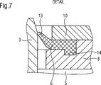
In
In dieser Zeichnung
Demnach werden weiter erfindungsgemäß beschrieben in
In
BezugszeichenlisteLIST OF REFERENCE NUMBERS
- 11
- Vorrichtung zur Befestigung und NiederhaltungDevice for fastening and holding down
- 22
- Dichtungsvorrichtung; Dichtungsring; Wellendichtring, ringförm. DichtelementSealing device; Sealing ring; Shaft seal ring. sealing element
- 33
- gegeneinander verdrehbares Teil; Drehkörperagainst each other rotatable part; rotating body
- 44
- gegeneinander verdrehbares Teil; Drehkörperagainst each other rotatable part; rotating body
- 55
- Aussparungrecess
- 66
- Staub- oder DichtlippeDust or sealing lip
- 77
- Schraubverbindungscrew
- 88th
- Aufnahmeplattemounting plate
- 99
- Materialaussparungmaterial cut
- 1010
- NiederhalteplatteHold-down plate
- 1111
- Ausnehmungrecess
- 1212
- Distanzelementspacer
- 1313
- nicht fixierter Bereich der Staub- oder Dichtlippenon-fixed area of the dust or sealing lip
- 1414
- fixiertes Ende der Staub- oder Dichtlippefixed end of the dust or sealing lip
- 1515
- weitere Schraubverbindungfurther screw connection
- 1616
- DichtungsanlaufflächenSeal contact surfaces
- 1717
- (Gemeinsame) Drehachse(Common) rotation axis
- 1818
- Wälzkörperrolling elements
- 1919
- Einzelne RingscheibeSingle ring disk
- 2020
- Bohrungdrilling
- XX
- Differenzlängelength difference
- I.I.
- Axiale Lage der Dichtungsvorrichtung nach einer ErstmontageAxial position of the sealing device after an initial assembly
- II.II.
- Axiale Lage der Dichtungsvorrichtung nach einer AustauschmontageAxial position of the sealing device after a replacement assembly
- DSDS
- Draufsicht auf Anordnung/Vorrichtung in axialer RichtungTop view of arrangement / device in the axial direction
- TT
- Dicke des DistanzelementesThickness of the spacer element
- DD
- Schmierbohrung zwischen den WellendichtringenLubricating hole between the shaft seals
- D1D1
- Auslassbohrungen zwischen den WellendichtringenOutlet holes between the shaft seals
- D2D2
- Belüftungsbohrungen zwischen den WellendichtringenVentilation holes between the shaft seals
- D3D3
- Schmierbohrungen zwischen Staubdichtung und äußerem WellendichtringLubricating holes between dust seal and outer shaft seal
- KK
- horizontale Hohlraumdefinierendehorizontal cavity defining
- ΔL.DELTA.L
- vertikale Hohlraumdefinierendevertical cavity defining
- MM
- Der axiale Abstand jener Stellen, an denen mehrere ringförmige Dichtelemente jeweils gegen die Dichtungsanlauffläche drückenThe axial distance of those points where press several annular sealing elements in each case against the sealing surface
Zitierte Patentliteratur:Cited patent literature:
-
EP 1927795 A1 EP 1927795 A1
Zitierte Nichtpatentliteratur:Quoted Non-Patent Literature:
-
Katalog des
Jahres 2009 des Dichtungsherstellers JAMES WALKER „Walkersele® Radial Lip Seals” Year 2009 of the seal manufacturer JAMES WALKER "Walkersele® Radial Lip Seals"
ZITATE ENTHALTEN IN DER BESCHREIBUNG QUOTES INCLUDE IN THE DESCRIPTION
Diese Liste der vom Anmelder aufgeführten Dokumente wurde automatisiert erzeugt und ist ausschließlich zur besseren Information des Lesers aufgenommen. Die Liste ist nicht Bestandteil der deutschen Patent- bzw. Gebrauchsmusteranmeldung. Das DPMA übernimmt keinerlei Haftung für etwaige Fehler oder Auslassungen.This list of the documents listed by the applicant has been generated automatically and is included solely for the better information of the reader. The list is not part of the German patent or utility model application. The DPMA assumes no liability for any errors or omissions.
Zitierte PatentliteraturCited patent literature
- EP 1927795 A1 [0003, 0007, 0007] EP 1927795 A1 [0003, 0007, 0007]
Zitierte Nicht-PatentliteraturCited non-patent literature
- JAMES WALKER „Walkersele® Radial Lip Seals” aus dem Jahr 2009. Seite 29 [0004] JAMES WALKER "Walkersele® Radial Lip Seals" from 2009. Page 29 [0004]
Claims (11)
Priority Applications (1)
| Application Number | Priority Date | Filing Date | Title |
|---|---|---|---|
| DE102011011165A DE102011011165A1 (en) | 2011-02-04 | 2011-02-04 | Sealing device i.e. oil seal, for sealing gap between inner ring and nose ring of three-row roller bearing utilized in wind power plant, has stabilization or fastening components whose location within material recess is adjustable |
Applications Claiming Priority (1)
| Application Number | Priority Date | Filing Date | Title |
|---|---|---|---|
| DE102011011165A DE102011011165A1 (en) | 2011-02-04 | 2011-02-04 | Sealing device i.e. oil seal, for sealing gap between inner ring and nose ring of three-row roller bearing utilized in wind power plant, has stabilization or fastening components whose location within material recess is adjustable |
Publications (1)
| Publication Number | Publication Date |
|---|---|
| DE102011011165A1 true DE102011011165A1 (en) | 2012-08-09 |
Family
ID=46547086
Family Applications (1)
| Application Number | Title | Priority Date | Filing Date |
|---|---|---|---|
| DE102011011165A Withdrawn DE102011011165A1 (en) | 2011-02-04 | 2011-02-04 | Sealing device i.e. oil seal, for sealing gap between inner ring and nose ring of three-row roller bearing utilized in wind power plant, has stabilization or fastening components whose location within material recess is adjustable |
Country Status (1)
| Country | Link |
|---|---|
| DE (1) | DE102011011165A1 (en) |
Cited By (17)
| Publication number | Priority date | Publication date | Assignee | Title |
|---|---|---|---|---|
| EP2722544A1 (en) * | 2012-10-19 | 2014-04-23 | Aktiebolaget SKF | Method for replacing sealing elements on a rolling bearing assembly and set of sealing elements |
| DE102013201643A1 (en) * | 2013-01-31 | 2014-07-31 | Aktiebolaget Skf | bearing arrangement |
| WO2015091719A1 (en) | 2013-12-20 | 2015-06-25 | Aktiebolaget Skf | Bearing arrangement |
| DE102014205811A1 (en) * | 2014-03-28 | 2015-10-01 | Aktiebolaget Skf | Bearing arrangement with sealing ring |
| JP2016048105A (en) * | 2014-08-28 | 2016-04-07 | 株式会社椿本チエイン | Side roller and chain with side roller |
| DE102015221412A1 (en) * | 2015-11-02 | 2017-05-04 | Aktiebolaget Skf | Sealing arrangement and wind turbine with the seal assembly |
| DE102013219118B4 (en) * | 2013-09-24 | 2017-05-11 | Schaeffler Technologies AG & Co. KG | Flanged housing unit |
| CN107165944A (en) * | 2017-06-27 | 2017-09-15 | 太仓望虞机械科技有限公司 | A kind of rolling bearing of adjustable sealing |
| DE102016116476A1 (en) * | 2016-09-02 | 2018-03-08 | Thyssenkrupp Ag | Rolling bearing and method for sealing a rolling bearing |
| WO2018174979A1 (en) * | 2017-03-24 | 2018-09-27 | The Timken Company | Seal carrier arrangement for large diameter bearing |
| US20190323559A1 (en) * | 2018-04-24 | 2019-10-24 | Aktiebolaget Skf | Slewing bearing with sealing arrangement |
| GB2573196A (en) * | 2018-04-24 | 2019-10-30 | Skf Ab | Slewing bearing with sealing arrangement |
| CN110513555A (en) * | 2019-08-23 | 2019-11-29 | 江苏腾旋科技股份有限公司 | Rotary joint for wind power generation equipment |
| CN114109833A (en) * | 2021-12-30 | 2022-03-01 | 石家庄通安机械有限公司 | Screw compressors |
| EP3967905A1 (en) * | 2020-09-11 | 2022-03-16 | Siemens Gamesa Renewable Energy A/S | Sealing ring arrangement, bearing and wind turbine |
| CN114658765A (en) * | 2020-12-22 | 2022-06-24 | 斯凯孚公司 | Rolling bearing with detachable sealing module |
| US11486444B2 (en) | 2019-11-12 | 2022-11-01 | Aktiebolaget Skf | Bearing with at least one sealing element and at least one adjusting shim for axially displacing said sealing element |
Citations (1)
| Publication number | Priority date | Publication date | Assignee | Title |
|---|---|---|---|---|
| EP1927795A1 (en) | 2006-11-28 | 2008-06-04 | Darwind Development & Demonstration BV | Oil seal device |
-
2011
- 2011-02-04 DE DE102011011165A patent/DE102011011165A1/en not_active Withdrawn
Patent Citations (1)
| Publication number | Priority date | Publication date | Assignee | Title |
|---|---|---|---|---|
| EP1927795A1 (en) | 2006-11-28 | 2008-06-04 | Darwind Development & Demonstration BV | Oil seal device |
Non-Patent Citations (2)
| Title |
|---|
| Jahres 2009 des Dichtungsherstellers JAMES WALKER "Walkersele(RTM) Radial Lip Seals" |
| JAMES WALKER "Walkersele(RTM) Radial Lip Seals" aus dem Jahr 2009. Seite 29 |
Cited By (30)
| Publication number | Priority date | Publication date | Assignee | Title |
|---|---|---|---|---|
| US9494197B2 (en) | 2012-10-19 | 2016-11-15 | Aktiebolaget Skf | Method for replacing sealing elements on a rolling bearing assembly and set of sealing elements |
| CN103775506A (en) * | 2012-10-19 | 2014-05-07 | Skf公司 | Method for replacing sealing elements on a rolling bearing assembly and set of sealing elements |
| EP2722544A1 (en) * | 2012-10-19 | 2014-04-23 | Aktiebolaget SKF | Method for replacing sealing elements on a rolling bearing assembly and set of sealing elements |
| DE102013201643A1 (en) * | 2013-01-31 | 2014-07-31 | Aktiebolaget Skf | bearing arrangement |
| EP2762738A2 (en) | 2013-01-31 | 2014-08-06 | Aktiebolaget SKF | Bearing assembly with rolling bearing and sealing assembly |
| DE102013201643B4 (en) * | 2013-01-31 | 2014-11-06 | Aktiebolaget Skf | bearing arrangement |
| DE102013219118B4 (en) * | 2013-09-24 | 2017-05-11 | Schaeffler Technologies AG & Co. KG | Flanged housing unit |
| DE102014200588A1 (en) * | 2013-12-20 | 2015-06-25 | Aktiebolaget Skf | bearing arrangement |
| DE102014200588B4 (en) * | 2013-12-20 | 2015-08-27 | Aktiebolaget Skf | bearing arrangement |
| US10107337B2 (en) | 2013-12-20 | 2018-10-23 | Aktiebolaget Skf | Bearing assembly |
| WO2015091719A1 (en) | 2013-12-20 | 2015-06-25 | Aktiebolaget Skf | Bearing arrangement |
| DE102014205811A1 (en) * | 2014-03-28 | 2015-10-01 | Aktiebolaget Skf | Bearing arrangement with sealing ring |
| DE102014205811B4 (en) * | 2014-03-28 | 2021-02-18 | Aktiebolaget Skf | Bearing arrangement with sealing ring |
| JP2016048105A (en) * | 2014-08-28 | 2016-04-07 | 株式会社椿本チエイン | Side roller and chain with side roller |
| DE102015221412A1 (en) * | 2015-11-02 | 2017-05-04 | Aktiebolaget Skf | Sealing arrangement and wind turbine with the seal assembly |
| DE102016116476A1 (en) * | 2016-09-02 | 2018-03-08 | Thyssenkrupp Ag | Rolling bearing and method for sealing a rolling bearing |
| WO2018174979A1 (en) * | 2017-03-24 | 2018-09-27 | The Timken Company | Seal carrier arrangement for large diameter bearing |
| CN107165944A (en) * | 2017-06-27 | 2017-09-15 | 太仓望虞机械科技有限公司 | A kind of rolling bearing of adjustable sealing |
| US11306781B2 (en) | 2018-04-24 | 2022-04-19 | Aktiebolaget Skf | Slewing bearing with sealing arrangement |
| US20190323559A1 (en) * | 2018-04-24 | 2019-10-24 | Aktiebolaget Skf | Slewing bearing with sealing arrangement |
| GB2573196A (en) * | 2018-04-24 | 2019-10-30 | Skf Ab | Slewing bearing with sealing arrangement |
| US10948019B2 (en) * | 2018-04-24 | 2021-03-16 | Aktiebolaget Skf | Slewing bearing with sealing arrangement |
| US11022176B2 (en) | 2018-04-24 | 2021-06-01 | Aktiebolaget Skf | Slewing bearing with sealing arrangement |
| US11022177B2 (en) | 2018-04-24 | 2021-06-01 | Aktiebolaget Skf | Slewing bearing with sealing arrangement |
| GB2573196B (en) * | 2018-04-24 | 2022-07-27 | Skf Ab | Slewing bearing with sealing arrangement |
| CN110513555A (en) * | 2019-08-23 | 2019-11-29 | 江苏腾旋科技股份有限公司 | Rotary joint for wind power generation equipment |
| US11486444B2 (en) | 2019-11-12 | 2022-11-01 | Aktiebolaget Skf | Bearing with at least one sealing element and at least one adjusting shim for axially displacing said sealing element |
| EP3967905A1 (en) * | 2020-09-11 | 2022-03-16 | Siemens Gamesa Renewable Energy A/S | Sealing ring arrangement, bearing and wind turbine |
| CN114658765A (en) * | 2020-12-22 | 2022-06-24 | 斯凯孚公司 | Rolling bearing with detachable sealing module |
| CN114109833A (en) * | 2021-12-30 | 2022-03-01 | 石家庄通安机械有限公司 | Screw compressors |
Similar Documents
| Publication | Publication Date | Title |
|---|---|---|
| DE102011011165A1 (en) | Sealing device i.e. oil seal, for sealing gap between inner ring and nose ring of three-row roller bearing utilized in wind power plant, has stabilization or fastening components whose location within material recess is adjustable | |
| DE102011011163A1 (en) | Device for fixing and holding down circumferential sealing device e.g. sealing ring used for sealing two mutually rotatable components in wind turbine, has receiving plate and hold-down plate fitted mutually in form-fitting manner | |
| EP3014149B1 (en) | Radial shaft seal | |
| EP2694832B1 (en) | Oil-lubricated anti-friction bearing | |
| DE2441520C2 (en) | Shaft seal for the rotors of a screw compressor using water injection | |
| DE909236C (en) | Method of lubricating bearings operating in a high vacuum | |
| DE102007060890A1 (en) | Sealing at least one shaft with at least one hydraulic seal | |
| DE102009014922A1 (en) | Greased double row rolling bearing and bearing system with such a rolling bearing and a lubricating device | |
| AT503578A4 (en) | SEALING ARRANGEMENT | |
| DE102013200356A1 (en) | Composite seal carrier for a direct drive main bearing of a wind turbine | |
| EP4390186B1 (en) | Subsea turbine sealing system | |
| EP3381861B1 (en) | Transmission with a lubrication system and a conveyor | |
| WO2007134576A1 (en) | Shaft seal | |
| DE102019131245B4 (en) | Bearing arrangement and method for mounting such a | |
| DE102012202365A1 (en) | Mounting arrangement for pressing rolling bearing inner ring on conical bearing seat surface of shaft, has push plate engaged with inner ring, and bonnet wing nut whose ball screw thread shoots share same axis of rotation with wing nut | |
| DE102016118052B4 (en) | Rolling bearing, sealing element and wind turbine | |
| DE102018119132A1 (en) | Double row tapered roller bearing | |
| DE102013019911A1 (en) | Fluid-dynamic bearing system for spindle motor to drive hard disk drive, has fixed and rotatable bearing components separated from each other, and sealants formed with air gap measured with flow constant for which preset value is applied | |
| EP4148303B1 (en) | Sealing arrangement with a rod seal, dispensing device for dispensing a fluid medium and rod seal | |
| EP4114572B1 (en) | Fibre treatment device | |
| DE202018102291U1 (en) | sealing unit | |
| EP2837512B1 (en) | Wheel suspension | |
| DE202010012138U1 (en) | rotary | |
| WO2017129578A1 (en) | Rolling bearing, wind turbine, and method for operating a rolling bearing | |
| DE10232443A1 (en) | High pressure seal for high speeds |
Legal Events
| Date | Code | Title | Description |
|---|---|---|---|
| R163 | Identified publications notified | ||
| R163 | Identified publications notified |
Effective date: 20130304 |
|
| R012 | Request for examination validly filed |
Effective date: 20130326 |
|
| R016 | Response to examination communication | ||
| R082 | Change of representative |
Representative=s name: WUESTHOFF & WUESTHOFF, PATENTANWAELTE PARTG MB, DE |
|
| R119 | Application deemed withdrawn, or ip right lapsed, due to non-payment of renewal fee |