DE102011011065A1 - Method and device for the high-precision measurement of surfaces - Google Patents
Method and device for the high-precision measurement of surfaces Download PDFInfo
- Publication number
- DE102011011065A1 DE102011011065A1 DE102011011065A DE102011011065A DE102011011065A1 DE 102011011065 A1 DE102011011065 A1 DE 102011011065A1 DE 102011011065 A DE102011011065 A DE 102011011065A DE 102011011065 A DE102011011065 A DE 102011011065A DE 102011011065 A1 DE102011011065 A1 DE 102011011065A1
- Authority
- DE
- Germany
- Prior art keywords
- distance
- sensor
- holder
- point
- meter
- Prior art date
- Legal status (The legal status is an assumption and is not a legal conclusion. Google has not performed a legal analysis and makes no representation as to the accuracy of the status listed.)
- Granted
Links
- 238000000034 method Methods 0.000 title claims abstract description 17
- 238000005259 measurement Methods 0.000 title claims description 17
- 239000000835 fiber Substances 0.000 description 8
- 238000012937 correction Methods 0.000 description 7
- 238000011156 evaluation Methods 0.000 description 6
- 230000003287 optical effect Effects 0.000 description 6
- 238000006073 displacement reaction Methods 0.000 description 5
- 238000011161 development Methods 0.000 description 4
- 230000008878 coupling Effects 0.000 description 2
- 238000010168 coupling process Methods 0.000 description 2
- 238000005859 coupling reaction Methods 0.000 description 2
- 238000001514 detection method Methods 0.000 description 2
- 238000004519 manufacturing process Methods 0.000 description 2
- 230000003595 spectral effect Effects 0.000 description 2
- BUHVIAUBTBOHAG-FOYDDCNASA-N (2r,3r,4s,5r)-2-[6-[[2-(3,5-dimethoxyphenyl)-2-(2-methylphenyl)ethyl]amino]purin-9-yl]-5-(hydroxymethyl)oxolane-3,4-diol Chemical compound COC1=CC(OC)=CC(C(CNC=2C=3N=CN(C=3N=CN=2)[C@H]2[C@@H]([C@H](O)[C@@H](CO)O2)O)C=2C(=CC=CC=2)C)=C1 BUHVIAUBTBOHAG-FOYDDCNASA-N 0.000 description 1
- 238000010276 construction Methods 0.000 description 1
- 230000001419 dependent effect Effects 0.000 description 1
- 238000013461 design Methods 0.000 description 1
- 230000000694 effects Effects 0.000 description 1
- 238000005516 engineering process Methods 0.000 description 1
- 230000005484 gravity Effects 0.000 description 1
- 238000005305 interferometry Methods 0.000 description 1
- 238000012423 maintenance Methods 0.000 description 1
- 238000000691 measurement method Methods 0.000 description 1
- 238000012986 modification Methods 0.000 description 1
- 230000004048 modification Effects 0.000 description 1
- 238000012544 monitoring process Methods 0.000 description 1
- 238000000275 quality assurance Methods 0.000 description 1
- 239000000523 sample Substances 0.000 description 1
- 238000001228 spectrum Methods 0.000 description 1
- 230000003068 static effect Effects 0.000 description 1
- 238000004441 surface measurement Methods 0.000 description 1
- 238000013519 translation Methods 0.000 description 1
Images

Classifications
-
- G—PHYSICS
- G01—MEASURING; TESTING
- G01B—MEASURING LENGTH, THICKNESS OR SIMILAR LINEAR DIMENSIONS; MEASURING ANGLES; MEASURING AREAS; MEASURING IRREGULARITIES OF SURFACES OR CONTOURS
- G01B21/00—Measuring arrangements or details thereof, where the measuring technique is not covered by the other groups of this subclass, unspecified or not relevant
- G01B21/02—Measuring arrangements or details thereof, where the measuring technique is not covered by the other groups of this subclass, unspecified or not relevant for measuring length, width, or thickness
- G01B21/04—Measuring arrangements or details thereof, where the measuring technique is not covered by the other groups of this subclass, unspecified or not relevant for measuring length, width, or thickness by measuring coordinates of points
-
- G—PHYSICS
- G01—MEASURING; TESTING
- G01B—MEASURING LENGTH, THICKNESS OR SIMILAR LINEAR DIMENSIONS; MEASURING ANGLES; MEASURING AREAS; MEASURING IRREGULARITIES OF SURFACES OR CONTOURS
- G01B11/00—Measuring arrangements characterised by the use of optical techniques
- G01B11/02—Measuring arrangements characterised by the use of optical techniques for measuring length, width or thickness
- G01B11/026—Measuring arrangements characterised by the use of optical techniques for measuring length, width or thickness by measuring distance between sensor and object
-
- G—PHYSICS
- G01—MEASURING; TESTING
- G01B—MEASURING LENGTH, THICKNESS OR SIMILAR LINEAR DIMENSIONS; MEASURING ANGLES; MEASURING AREAS; MEASURING IRREGULARITIES OF SURFACES OR CONTOURS
- G01B11/00—Measuring arrangements characterised by the use of optical techniques
- G01B11/24—Measuring arrangements characterised by the use of optical techniques for measuring contours or curvatures
-
- G—PHYSICS
- G01—MEASURING; TESTING
- G01B—MEASURING LENGTH, THICKNESS OR SIMILAR LINEAR DIMENSIONS; MEASURING ANGLES; MEASURING AREAS; MEASURING IRREGULARITIES OF SURFACES OR CONTOURS
- G01B21/00—Measuring arrangements or details thereof, where the measuring technique is not covered by the other groups of this subclass, unspecified or not relevant
- G01B21/20—Measuring arrangements or details thereof, where the measuring technique is not covered by the other groups of this subclass, unspecified or not relevant for measuring contours or curvatures, e.g. determining profile
Landscapes
- Physics & Mathematics (AREA)
- General Physics & Mathematics (AREA)
- Length Measuring Devices By Optical Means (AREA)
- Length Measuring Devices With Unspecified Measuring Means (AREA)
Abstract
Die vorliegende Erfindung betrifft eine Vorrichtung und ein Verfahren zur Vermessung zumindest eines Oberflächenabschnitts eines auf einem Träger (12) gelagerten Objekts (14), mit:
— zumindest einem gegenüber dem Träger (12) fixierbaren Referenzobjekt (18, 20) und
— einem in zumindest einer ersten Richtung (x, y) gegenüber dem Referenzobjekt (18, 20) beweglichen Halter (26), an welchem ein Referenzkörper (28) sowie ein Abstandsmesser (34, 36) angeordnet sind, die relativ zueinander drehbar gelagert sind, wobei der Abstandsmesser (34, 36) dazu ausgebildet ist, einen ersten Abstand (38) zu einem ersten Punkt (52) des Oberflächenabschnitts des Objekts (14) und einen zweiten Abstand (40) zu einem hiermit korrespondierenden zweiten Punkt (54) des Referenzkörpers (28) zu bestimmen.The present invention relates to an apparatus and a method for measuring at least one surface section of an object (14) mounted on a carrier (12), comprising:
- At least one relative to the carrier (12) fixable reference object (18, 20) and
- A in at least a first direction (x, y) relative to the reference object (18, 20) movable holder (26) on which a reference body (28) and a distance meter (34, 36) are arranged, which are rotatably mounted relative to each other wherein the distance meter (34, 36) is adapted to provide a first distance (38) to a first point (52) of the surface portion of the object (14) and a second distance (40) to a corresponding second point (54) of the object Determine reference body (28).

Description
Die vorliegende Erfindung betrifft ein Verfahren sowie eine Vorrichtung zur hochpräzisen Vermessung der Topologie bzw. der Oberfläche eines beliebigen Objekts auf der Grundlage einer optischen, berührungslosen Abtastung des Objekts.The present invention relates to a method and a device for high-precision measurement of the topology or the surface of any object on the basis of an optical, non-contact scanning of the object.
Stand der TechnikState of the art
Zur Qualitätssicherung als auch zur Überwachung von industriellen Herstellungsprozessen, insbesondere im Bereich der Feinwerktechnik, Optik sowie in der Fertigungstechnik mechanischer und elektrischer Mikrostrukturen besteht ein wachsender Bedarf hinsichtlich einer möglichst hochauflösenden und präzisen Vermessung von Werkstück-Oberflächen.For quality assurance as well as for the monitoring of industrial manufacturing processes, in particular in the field of precision engineering, optics and in the manufacturing technology of mechanical and electrical microstructures, there is an increasing demand for the highest possible and precise measurement of workpiece surfaces.
So ist beispielsweise aus der
Ferner ist aus der
Bei derartigen, etwa in einer Scanbewegung die Oberfläche eines Objektes berührungslos abtastenden Sensors spielt die Bewegung und die Positioniergenauigkeit des Sensors gegenüber dem zu vermessenden Objekt eine entscheidende Rolle.In the case of such a sensor, which scans the surface of an object without contact in a scanning movement, the movement and the positioning accuracy of the sensor relative to the object to be measured plays a decisive role.
Um den Abstand zwischen dem Abstandssensor und der zu vermessenden Oberfläche präzise ermitteln zu können, muss der Sensor im Wesentlichen orthogonal zur zu vermessenden Oberfläche ausgerichtet sein und seine Ausrichtung entsprechend der Kontur des zu vermessenden Objekts anpassen. Für diese Anpassung sind sowohl Translations- als auch Drehbewegungen des Sensors durchzuführen.In order to accurately determine the distance between the distance sensor and the surface to be measured, the sensor must be aligned substantially orthogonal to the surface to be measured and adjust its orientation according to the contour of the object to be measured. For this adjustment both translational and rotational movements of the sensor are to be carried out.
Während eine Translationsbewegung des Sensors mittels weiterer Abstandssensoren gegenüber einer feststehenden Referenz mit ausreichend hoher Genauigkeit ermittelt. werden kann, erweist sich jedoch gerade ein Drehen bzw. Verkippen des Sensors als problematisch.While a translational movement of the sensor determined by means of further distance sensors with respect to a fixed reference with sufficiently high accuracy. However, turning or tilting the sensor proves problematic.
Bei der geforderten Messgenauigkeit im Nanometer- oder Subnanometerbereich bewirkt eine Drehung des Sensors ferner auch stets eine nicht zu vernachlässigende translatorische Verschiebung des Sensors gegenüber der den Sensor tragenden Plattform. So muss das Messsignal des Sensors zumindest um die durch die Drehbewegung des Sensors verursachte Positionsverschiebung des Sensors korrigiert werden. Die mechanischen Toleranzen des Sensor-Lagers verursachen nicht reproduzierbare Positionsveränderungen des Sensors in unterschiedlichen Winkelstellungen. Es ist daher erforderlich, die Position des Sensors für jede mögliche Ausrichtung des Sensors präzise zu bestimmen.In the case of the required measuring accuracy in the nanometer or subnanometer range, rotation of the sensor furthermore always results in a not insignificant translatory displacement of the sensor relative to the platform carrying the sensor. Thus, the measuring signal of the sensor must be corrected at least by the positional displacement of the sensor caused by the rotational movement of the sensor. The mechanical tolerances of the sensor bearing cause irreproducible position changes of the sensor in different angular positions. It is therefore necessary to precisely determine the position of the sensor for each possible orientation of the sensor.
Aufgabetask
Der vorliegenden Erfindung liegt demgegenüber die Aufgabe zugrunde, eine Vorrichtung und ein entsprechendes Verfahren zum hochpräzisen Vermessen von Oberflächen von Objekten bereitzustellen, wobei etwaige, z. B. durch eine Drehbewegung des Sensorkopfs bedingte Positionsungenauigkeiten des Sensors in einfacher Art und Weise bestimmt und entsprechend kompensiert werden sollen. Die Vorrichtung soll sich dabei durch einen möglichst einfachen, platzsparenden sowie kostengünstig zu implementierenden Aufbau auszeichnen. Auch soll sie möglichst widerstandsfähig gegenüber äußeren Störeinflüssen ausgebildet sein.The present invention is based on the object to provide an apparatus and a corresponding method for the high-precision measurement of surfaces of objects, wherein any, z. B. determined by a rotational movement of the sensor head position inaccuracies of the sensor in a simple manner and should be compensated accordingly. The device should be characterized by a simple, space-saving and inexpensive to implement construction. Also, it should be designed as resistant to external interference.
Erfindung und vorteilhafte WirkungenInvention and advantageous effects
Diese Aufgabe wird mit einer Vorrichtung gemäß dem unabhängigen Patentanspruch 1 sowie mit einem Verfahren nach Patentanspruch 14 gelöst, wobei vorteilhafte Ausgestaltungen der Erfindung jeweils Gegenstand abhängiger Ansprüche sind.This object is achieved with a device according to the
Die erfindungsgemäße Vorrichtung ist zur Vermessung zumindest eines Oberflächenabschnitts eines auf einem Träger gelagerten Objekts ausgebildet. Die Vorrichtung weist dabei zumindest ein gegenüber dem Träger fixierbares Referenzobjekt auf. Träger und Referenzobjekt müssen dabei nicht zwingend miteinander verbunden oder mechanisch gekoppelt sein. Es ist grundsätzlich ausreichend, wenn die Schwerpunkte oder Symmetrieachsen des Objektträgers, des Objekts selbst und/oder des Referenzobjekts während einer Vermessungsprozedur nicht zueinander bewegt werden, sondern statisch an ihrer jeweiligen Position verweilen; sozusagen zueinander ortsfixiert sind. Eine Drehbewegung des Objekts, bevorzugt um eine seiner Symmetrieachsen ist dabei zur Vermessung seiner Gesamtoberfläche vorgesehen. Für die Vermessung der Oberfläche des Objekts ist die Ermittlung eines relativen Abstandes zum Referenzobjekt jedoch nicht erforderlich. Die Vorrichtung weist ferner einen in zumindest einer ersten Richtung gegenüber dem Referenzobjekt beweglichen Halter auf. An diesem Halter sind ein Referenzkörper sowie ein Abstandsmesser oder eine Abstandsmesseinrichtung angeordnet. Abstandsmesser und Referenzkörper sind dabei relativ zueinander drehbar gelagert.The device according to the invention is designed to measure at least one surface section of an object mounted on a carrier. In this case, the device has at least one reference object which can be fixed relative to the carrier. Carrier and reference object need not necessarily be connected to each other or mechanically coupled. It is basically sufficient if the centers of gravity or axes of symmetry of the object carrier, of the object itself and / or of the reference object are not moved relative to each other during a surveying procedure, but remain static at their respective positions; are fixed to each other, so to speak. A rotational movement of the object, preferably about one of its axes of symmetry is provided for the measurement of its total surface. For the measurement of the surface of the object, however, the determination of a relative distance to the reference object is not required. The device further has a holder movable in at least a first direction relative to the reference object. On this holder, a reference body and a distance meter or a distance measuring device are arranged. Distance meter and reference body are rotatably mounted relative to each other.
Der Abstandsmesser ist ferner dazu ausgebildet, einen ersten Abstand zu einem ersten Punkt des zu vermessenden Oberflächenabschnitts des Objekts als auch einen zweiten Abstand zu einem hiermit korrespondierenden zweiten Punkt des Referenzkörpers zu bestimmen. Der mittels des Abstandsmessers zu ermittelnde erste Abstand stellt das eigentliche Messsignal dar, während anhand des gemessenen zweiten Abstands eine etwa rotationsbedingte Relativverschiebung zwischen dem Abstandsmesser und dem, ebenfalls am beweglichen Halter angeordneten, Referenzkörper ermittelt werden kann. Anhand des zu messenden zweiten Abstands kann insoweit eine Abstandskorrektur für den ersten gemessenen Abstand erfolgen.The distance meter is further configured to determine a first distance to a first point of the surface section of the object to be measured as well as a second distance to a second point of the reference body corresponding thereto. The first distance to be determined by means of the distance meter represents the actual measurement signal, while on the basis of the measured second distance an approximately rotation-related relative displacement between the distance meter and the reference body also arranged on the movable holder can be determined. On the basis of the second distance to be measured, a distance correction for the first measured distance can be made.
Eine etwa durch die Drehbewegung des Abstandsmessers hervorgerufene nicht reproduzierbare Verschiebung des Sensors und ein daraus resultierende Verfälschung der Messwerte kann durch die Bestimmung des zweiten Abstands gegenüber einem, hinsichtlich seiner Kontur und Position bekannten Referenzkörper kompensiert werden. Ein Offset zwischen einer Drehachse und einer Messachse des Abstandsmessers kann durch Ermittlung der ersten und zweiten Abstände sowie durch eine relative Ausrichtung von Referenzkörper und Abstandsmesser rechnerisch kompensiert werden.A non-reproducible displacement of the sensor caused by the rotational movement of the distance meter and a resulting falsification of the measured values can be compensated for by determining the second distance from a reference body known with regard to its contour and position. An offset between an axis of rotation and a measuring axis of the distance meter can be computationally compensated by determining the first and second distances and by a relative orientation of the reference body and distance meter.
Die Position des beweglichen Halters in Bezug auf das zumindest eine Referenzobjekt wird bevorzugt mit zumindest einem weiteren Abstandsmesser, insbesondere mit einer Anzahl Abstandssensoren ermittelt, um auf mittelbarem Wege die Position des Abstandsmessers gegenüber dem Referenzobjekt bestimmen zu können.The position of the movable holder with respect to the at least one reference object is preferably determined with at least one further distance meter, in particular with a number of distance sensors, in order to indirectly determine the position of the distance meter relative to the reference object.
Nach einer bevorzugten Weiterbildung weist der am beweglichen Halter angeordnete Abstandsmesser einen dem zu vermessenden Objekt zugewandten ersten Abstandssensor und einen zweiten, dem Referenzkörper zugewandten Abstandssensor auf. Der erste Abstandssensor dient einer Abstandsmessung zwischen Abstandsmesser und zu vermessendem Objekt, während der zweite Abstandssensor zur Bestimmung der Position des Abstandsmessers bzw. des ersten Abstandssensors relativ zum beweglichen Halter dient. Die Position des Halters wiederum kann mittels zumindest eines, bevorzugt mittels zweier in unterschiedlichen Richtungen ausgerichteter Sensoren gegenüber dem zumindest einen, bevorzugt gegenüber zwei Referenzobjekten bestimmt werden.According to a preferred development, the distance meter arranged on the movable holder has a first distance sensor facing the object to be measured and a second distance sensor facing the reference body. The first distance sensor serves to measure the distance between the distance meter and the object to be measured, while the second distance sensor serves to determine the position of the distance meter or of the first distance sensor relative to the movable holder. The position of the holder in turn can be determined by means of at least one, preferably by means of two aligned in different directions sensors relative to the at least one, preferably with respect to two reference objects.
In Weiterbildung hiervon ist der Abstandsmesser drehbar am beweglichen Halter gelagert und der Referenzkörper ist drehfest am Halter angeordnet. Die Fixierung des Referenzkörpers am Halter ermöglicht insbesondere eine hochpräzise Bestimmung der Position des Abstandsmessers gegenüber dem Halter selbst.In a further development thereof, the distance meter is rotatably mounted on the movable holder and the reference body is rotatably mounted on the holder. The fixation of the reference body on the holder in particular allows a high-precision determination of the position of the distance blade relative to the holder itself.
In Weiterbildung hiervon weist der Referenzkörper eine auf die Drehbeweglichkeit des Abstandsmessers abgestimmte Referenzfläche auf. Die Referenzfläche ist derart ausgebildet, dass ein vom zweiten Abstandssensor emittiertes Messsignal von der Referenzfläche reflektiert und vom zweiten Abstandssensor wieder detektiert werden kann.In a further development thereof, the reference body has a reference surface tuned to the rotational mobility of the distance meter. The reference surface is designed such that a measurement signal emitted by the second distance sensor can be reflected by the reference surface and detected again by the second distance sensor.
Es ist dabei insbesondere vorgesehen, dass die Referenzfläche als eine Art Hohlspiegel mit einer im Wesentlichen kreissegmentartigen Geometrie ausgebildet ist, wobei der Mittelpunkt des Hohlspiegels im Wesentlichen mit der Drehachse des Abstandsmessers bzw. mit der Drehachse des ersten und/oder des zweiten Abstandssensors zusammenfällt. Die Referenzfläche ist insbesondere hohlzylindrischer Gestalt, wobei sich die gedachte Zylinderachse im Wesentlichen parallel zur Drehachse des Abstandsmessers erstreckt. Abweichend hiervon kann die Referenzfläche auch eine polygonale Form oder eine beliebige, mittels Kalibrierung ermittelbare konkav gekrümmte Formgebung aufweisen.It is provided in particular that the reference surface is formed as a kind of concave mirror with a substantially circular segment-like geometry, wherein the center of the concave mirror coincides substantially with the axis of rotation of the distance meter or with the axis of rotation of the first and / or the second distance sensor. The reference surface is in particular a hollow cylindrical shape, wherein the imaginary cylinder axis extends substantially parallel to the axis of rotation of the distance meter. Notwithstanding this, the reference surface may also have a polygonal shape or any concave curved shape that can be determined by means of calibration.
Nach einer weiteren bevorzugten Ausgestaltung sind der erste und der zweite Abstandssensor des Abstandsmessers diametral entgegengesetzt zueinander ausgerichtet bzw. angeordnet. Der erste Abstandssensor ist bevorzugt derart ausgerichtet, dass seine Messachse bzw. dass die von ihm emittierten optischen Messsignale annähernd orthogonal auf dem zu vermessenden Oberflächenabschnitt auftreffen und dort wieder zum ersten Abstandssensor reflektiert werden. Dadurch, dass der zweite Abstandssensor in die entgegengesetzte Richtung ausgerichtet ist, kann der dabei ermittelte Abstand unmittelbar zur Korrektur des Messsignals des ersten Abstandssensors Verwendung finden.According to a further preferred embodiment, the first and the second distance sensor of the distance meter are aligned or arranged diametrically opposite to each other. Of the The first distance sensor is preferably oriented in such a way that its measuring axis or that of the optical measuring signals emitted by it impinge approximately orthogonally on the surface section to be measured, where they are reflected back to the first distance sensor. Because the second distance sensor is oriented in the opposite direction, the distance determined thereby can be used directly for correcting the measurement signal of the first distance sensor.
Der vom zweiten Abstandssensor gemessene zweite Abstand ist ein direktes Maß für die vorzunehmende Abstandskorrektur für den ersten Abstandssensors. Es ist hierbei lediglich erforderlich, die Kontur bzw. Position und Verlauf der Referenzfläche des Referenzkörpers im Zuge einer Kalibrierung der Vorrichtung einmal präzise zu bestimmen, damit eine entsprechende, der jeweils vorherrschenden Ausrichtung bzw. Winkelstellung des Abstandsmessers entsprechende Längen- oder Abstandskorrektur der ermittelten Messwerte erfolgen kann. Für die Kalibrierung der Vorrichtung ist ein Abgleich des zweiten Abstands zu jeder möglichen Winkelstellung des Abstandsmessers in Bezug auf den Referenzkörper vorzunehmen.The second distance measured by the second distance sensor is a direct measure of the distance correction to be made for the first distance sensor. In this case, it is only necessary to determine the contour or position and course of the reference surface of the reference body once in the course of a calibration of the device, so that a corresponding length or distance correction of the determined measured values corresponding to the respective prevailing orientation or angular position of the distance meter takes place can. For the calibration of the device, an adjustment of the second distance to each possible angular position of the distance meter with respect to the reference body is made.
Nach einer weiteren bevorzugten Ausgestaltung ist der Abstand zwischen dem Referenzobjekt und dem beweglichen Halter mittels zumindest eines dritten Abstandssensors bestimmbar. Der dritte Abstandssensor kann dabei entweder am Referenzobjekt oder am Halter selbst angeordnet sein. Zur Bestimmung des Abstandes bzw. der Position des Halters in Bezug auf das Referenzobjekt weist der Halter bzw. das Referenzobjekt eine entsprechende Mess- oder Spiegelfläche auf. Insbesondere für eine die gesamte Oberfläche des zu vermessenden Objekts abtastende Bewegung des Halters ist ein zweites Referenzobjekt vorgesehen, wobei der Halter auch gegenüber dem zweiten Referenzobjekt beweglich gelagert ist. Eine zweidimensionale Beweglichkeit des Halters gegenüber den sich bevorzugt in einer entsprechenden Ebene erstreckenden Referenzobjekten ermöglicht ein Verfahren des Halters bevorzugt in der Ebene senkrecht zur Drehachse des Abstandsmessers. Insoweit ist es von Vorteil, wenn ein vierter Abstandssensor zur zweidimensionalen Positionsbestimmung des Halters in Bezug auf die Referenzobjekte Verwendung findet.According to a further preferred embodiment, the distance between the reference object and the movable holder can be determined by means of at least one third distance sensor. The third distance sensor can be arranged either on the reference object or on the holder itself. For determining the distance or the position of the holder with respect to the reference object, the holder or the reference object has a corresponding measuring or mirror surface. In particular, for a movement of the holder scanning the entire surface of the object to be measured, a second reference object is provided, wherein the holder is also movably mounted relative to the second reference object. A two-dimensional mobility of the holder relative to the preferably in a corresponding plane extending reference objects allows a method of the holder preferably in the plane perpendicular to the axis of rotation of the distance meter. In that regard, it is advantageous if a fourth distance sensor for two-dimensional position determination of the holder with respect to the reference objects is used.
Weiterhin kann vorgesehen werden, dass der das Objekt lagernde Träger drehbar gelagert ist, um sämtliche zu vermessende Oberflächenpunkte des Objekts in die von der Messeinrichtung vorgegebene Ebene zu verlagern.Furthermore, it can be provided that the carrier supporting the object is rotatably mounted in order to displace all surface points of the object to be measured into the plane predefined by the measuring device.
In einer alternativen Ausgestaltung kann ferner vorgesehen werden, dass der erste Punkt, welcher auf einem zu vermessenden Oberflächenabschnitt des Objektes liegt und der zweite Punkt, der eine der Winkelstellung des Abstandsmessers entsprechende Stelle auf dem Referenzkörper bzw. auf seiner Referenzfläche definiert, auf einer gedachten Linie liegen bzw. eine Linie definieren, entlang derer der erste und der zweite Abstandssensor ausgerichtet sind. Mit anderen Worten sind die beiden diametral entgegengesetzt ausgerichteten Abstandssensoren des Abstandsmessers derart ausgerichtet, dass ein vom ersten Abstandssensor ausgehender Messstrahl im Wesentlichen senkrecht auf die zu vermessende Oberfläche auftrifft. Durch jene Ausrichtung ergibt sich zwangsläufig die Position des zweiten Punkts auf dem Referenzkörper.In an alternative embodiment, it may further be provided that the first point, which lies on a surface section of the object to be measured and the second point, which defines a position corresponding to the angular position of the distance meter on the reference body or on its reference surface, on an imaginary line lie or define a line along which the first and the second distance sensor are aligned. In other words, the two diametrically oppositely oriented distance sensors of the distance meter are aligned in such a way that a measuring beam originating from the first distance sensor impinges substantially perpendicularly on the surface to be measured. By that orientation inevitably results in the position of the second point on the reference body.
Nach einer weiteren bevorzugten Ausgestaltung sind der Träger, welcher der drehbaren Lagerung des zu vermessenden Objekts dient, und das Referenzobjekt voneinander mechanisch entkoppelt, d. h. sie können innerhalb vorgegebener Grenzen beliebig zueinander angeordnet sein. Die Positionierung des Trägers relativ zum Referenzobjekt muss für die Durchführung einer Oberflächenvermessung des Objekts nicht ermittelt werden. Im Zuge einer scannenden oder abtastenden Bewegung wird der bewegliche Halter mit seinem Referenzkörper gegenüber dem Objekt bewegt. Der Abstandsmesser mit seinen beiden entgegengesetzt ausgerichteten Abstandssensoren misst dabei jeweils den Abstand zwischen dem Referenzkörper und der zu vermessenden Oberfläche des Objekts anhand einer Vielzahl einzelner Messpunkte. Aus einem Vergleich der ermittelten Abstandsdaten kann schließlich auf die Kontur und die Oberflächenbeschaffenheit des zu vermessenden Objekts geschlossen werden.According to a further preferred embodiment, the carrier, which serves for the rotatable mounting of the object to be measured, and the reference object are mechanically decoupled from each other, i. H. they can be arranged within given limits arbitrarily to each other. The positioning of the carrier relative to the reference object need not be determined for performing a surface measurement of the object. In the course of a scanning or scanning motion of the movable holder is moved with its reference body relative to the object. The distance meter with its two oppositely oriented distance sensors measures the distance between the reference body and the surface of the object to be measured on the basis of a plurality of individual measuring points. From a comparison of the determined distance data can finally be concluded that the contour and the surface condition of the object to be measured.
Nach einer weiteren bevorzugten Ausgestaltung ist eine Steuereinheit vorgesehen, die dazu ausgebildet ist, zumindest den ersten Abstandssensor entlang der Flächennormalen des ersten Punkts des zu vermessenden Oberflächenabschnitts des Objekts auszurichten. Die Steuereinheit dient bevorzugt einer automatischen Justage und Drehbewegung des Abstandssensors derart, dass die von ihm emittierten Signale vom Objekt zurückreflektiert werden. Bei einer verspiegelten Oberfläche des Objekts erfolgt eine Rückreflexion im Bereich um 180° gegenüber dem emittierten Signal. Je nach Sensorausgestaltung kann auch bis zu 3°, 5°, oder 10° von der Oberflächennormalen des zu untersuchenden Oberflächenabschnitts abgewichen werden. Bei rauen oder streuenden Oberflächen können andere, hiervon abweichende Ausrichtungen des Sensors gegenüber der Flächennormalen erforderlich werden. Beispielsweise kann die Ausrichtung des Sensors von einer Steuereinheit vorgegeben werden.According to a further preferred embodiment, a control unit is provided, which is designed to align at least the first distance sensor along the surface normal of the first point of the surface section of the object to be measured. The control unit preferably serves for automatic adjustment and rotational movement of the distance sensor in such a way that the signals emitted by it are reflected back by the object. In the case of a mirrored surface of the object, a return reflection takes place in the region of 180 ° with respect to the emitted signal. Depending on the sensor design, deviations of up to 3 °, 5 °, or 10 ° from the surface normal of the surface section to be examined may be deviated. In the case of rough or scattering surfaces, other deviations of the sensor from the surface normal may be necessary. For example, the orientation of the sensor can be specified by a control unit.
Es erweist sich als besonders vorteilhaft, dass der zweite, vom zweiten Abstandssensor ermittelbare Abstand zum Referenzkörper unmittelbar zur Korrektur des vom ersten Sensor ermittelbaren Abstandswertes verwendet werden kann. Die Ausrichtung der beiden Sensoren oder des Abstandsmessers in Bezug auf das zumindest eine Referenzobjekt spielt dabei keine Rolle. Für die Korrektur oder Kompensation einer durch Drehung und/oder Verschiebung des Sensors bedingte Änderung des ersten Abstandes müssen insbesondere keine Positionskoordinaten des ersten und/oder des zweiten Sensors ermittelt werden. Die beiden von den zueinander entgegengesetzt ausgerichteten Sensoren ermittelbaren Abstände können einer Steuereinheit zur Durchführung einer unmittelbaren Fehlerkorrektur zugeführt werden.It proves to be particularly advantageous that the second, determinable by the second distance sensor distance to the reference body directly to Correction of the distance value that can be determined by the first sensor can be used. The orientation of the two sensors or the distance meter with respect to the at least one reference object plays no role. In particular, no position coordinates of the first and / or the second sensor need to be determined for the correction or compensation of a change in the first distance caused by rotation and / or displacement of the sensor. The two distances that can be determined by the mutually oppositely oriented sensors can be supplied to a control unit for performing an immediate error correction.
Nach einer weiteren bevorzugten Ausgestaltung sind sämtliche Abstandssensoren faseroptisch mit zumindest einer Lichtquelle gekoppelt. Eine freie Strahlpropagation erfolgt lediglich zwischen den jeweiligen Abstandssensoren und einer jeweils zugeordneten spiegelnden Referenzfläche. Die faseroptische Anbindung ist vergleichsweise wartungsarm und erfordert in aller Regel keine Nachjustage im Betrieb der Vorrichtung.According to a further preferred embodiment, all distance sensors are fiber-optically coupled to at least one light source. A free beam propagation takes place only between the respective distance sensors and a respectively associated specular reference surface. The fiber optic connection is relatively low maintenance and usually requires no readjustment during operation of the device.
Nach einer weiteren vorteilhaften Ausgestaltung ist ferner zumindest der erste, dem Objekt zugewandte Abstandssensor mit mehreren Lichtquellen unterschiedlicher Wellenlänge gekoppelt, um den Abstand zum Objekt mittels eines Mehrwellenlängen-Messprinzips zu bestimmen. Ein solches Mehrwellenlängen-Messverfahren ermöglicht eine hochpräzise Abstandsmessung mit einer Auflösung im Nanometer- oder Subnanometerbereich und kann ferner einen Eindeutigkeitsbereich des Messergebnisses bis in den Millimeterbereich hinein bereitstellen. Bevorzugt werden als Lichtquellen weitgehend monochromatische Laser verwendet, deren Wellenlänge im Bereich zwischen 1520 und 1630 nm liegt. Die verwendeten Laserwellenlängen liegen typischerweise im S-, C- oder L-Band des optischen Telekommunikationsspektrums. Die Laserlichtquellen sind jedoch keineswegs auf den Infrarot-Spektralbereich beschränkt. So können grundsätzlich auch Wellenlängen im sichtbaren oder UV-Spektralbereich Verwendung finden.According to a further advantageous embodiment, furthermore, at least the first distance sensor facing the object is coupled to a plurality of light sources of different wavelengths in order to determine the distance to the object by means of a multi-wavelength measurement principle. Such a multi-wavelength measuring method enables a high-precision distance measurement with a resolution in the nanometer or subnanometer range and can furthermore provide a uniqueness range of the measurement result down to the millimeter range. As light sources, monochromatic lasers whose wavelength is in the range between 1520 and 1630 nm are preferably used. The laser wavelengths used are typically in the S, C or L band of the optical telecommunication spectrum. However, the laser light sources are by no means limited to the infrared spectral range. In principle, wavelengths in the visible or UV spectral range can also be used.
Prinzipiell ist die Erfindung auch für einen mit lediglich einer Wellenlänge operierenden Abstandsmesser implementierbar. Mittels eines Mehrwellenlängen-Messverfahrens kann jedoch der Eindeutigkeitsbereich der empfangenen Signale sichtlich vergrößert werden. Die Abstandsmessung zum zu vermessenden Objekt erfolgt bevorzugt nach dem in der
In einem weiteren, nebengeordneten Aspekt betrifft die Erfindung ferner ein Verfahren zur Vermessung zumindest eines Oberflächenabschnitts eines auf einem Träger gelagerten Objekts. Das Objekt ist dabei zumindest gegenüber einem ortsfesten Referenzobjekt fixiert und ein Halter, an welchem ein Referenzkörper sowie ein Abstandsmesser angeordnet sind, wird in einer das Objekt berührungslos abtastenden Bewegung in zumindest einer ersten Richtung gegenüber dem Referenzobjekt als auch gegenüber dem zu vermessenden Objekt bewegt. Im Zuge dieser abtastenden Bewegung wird mittels des Abstandsmessers ein erster Abstand zu einem ersten Punkt des Oberflächenabschnitts des Objekts sowie ein zweiter Abstand zu einem hiermit korrespondierenden zweiten Punkt des Referenzkörpers bestimmt. Aus der Messung dieser beiden Abstände kann ein Abstand der beiden Punkte präzise bestimmt werden.In a further, independent aspect, the invention further relates to a method for measuring at least one surface section of an object mounted on a carrier. The object is fixed at least to a fixed reference object and a holder on which a reference body and a distance meter are arranged is moved in a non-contact scanning motion object in at least a first direction relative to the reference object and with respect to the object to be measured. In the course of this scanning movement, a first distance to a first point of the surface section of the object as well as a second distance to a second point of the reference body corresponding thereto are determined by means of the distance meter. From the measurement of these two distances, a distance between the two points can be precisely determined.
Da die Position des zweiten Punkts auf dem Referenzkörper bekannt ist und die Lage bzw. relative Position des Referenzkörpers gegenüber dem Referenzobjekt mittels zumindest einem weiteren Abstandssensor gemessen wird, kann auf diese Art und Weise die Position des ersten, auf dem Objekt befindlichen Punktes gegenüber dem bekannten Referenzobjekt eindeutig und mit einer Präzision im Nanometer- oder Subnanometerbereich bestimmt werden.Since the position of the second point on the reference body is known and the position or relative position of the reference body relative to the reference object is measured by means of at least one further distance sensor, in this way the position of the first point located on the object can be compared with the known one Reference object can be determined clearly and with a precision in the nanometer or subnanometer range.
Insoweit ist nach einer Weiterbildung zumindest ein dritter Abstandssensor vorgesehen, der den Abstand zwischen dem Referenzobjekt und dem Halter zumindest entlang einer ersten Richtung bestimmt.In that regard, according to a development, at least one third distance sensor is provided which determines the distance between the reference object and the holder at least along a first direction.
Von Vorteil ist ferner ein zumindest vierter Abstandssensor vorgesehen, der bevorzugt im Wesentlichen senkrecht zum dritten Sensor ausgerichtet ist, um die Position des Halters in der von einem ersten und einem zweiten Referenzobjekt aufgespannten Ebene zu bestimmen.Advantageously, an at least fourth distance sensor is further provided, which is preferably aligned substantially perpendicular to the third sensor to determine the position of the holder in the plane defined by a first and a second reference object level.
Schließlich ist vorgesehen, dass anhand des ersten und des zweiten Abstandes, mithin des Abstandes zwischen Referenzkörper und zu vermessendem Objekt sowie anhand des Abstandes zwischen dem Referenzobjekt und dem beweglichen Halter die Position des ersten Punkts des zu vermessenden Oberflächenabschnitts des Objektes in Bezug auf das Referenzobjekt bestimmt wird. Im Zuge einer abtastenden oder scannenden Bewegung des Halters, bzw. einer hiermit sogar kombinierten Drehung des Referenzobjekts kann dessen gesamte Oberfläche punktweise abgetastet und mit einer Präzision im Nanometer- oder Subnanometerbereich vermessen werden.Finally, it is provided that the position of the first point of the surface section of the object to be measured with respect to the reference object is determined on the basis of the first and the second distance, thus the distance between the reference body and the object to be measured, and the distance between the reference object and the movable holder becomes. In the course of a scanning or scanning movement of the holder, or a hereby even combined rotation of the reference object whose entire surface can be scanned point by point and measured with a precision in the nanometer or subnanometer range.
Kurzbeschreibung der Figuren Brief description of the figures
Weitere Ziele, Merkmale sowie vorteilhafte Anwendungsmöglichkeiten der Erfindung werden in der nachfolgenden Darstellung eines Ausführungsbeispiels näher erläutert. Dabei bilden sämtliche im Text beschriebene als auch in den Figuren bildlich dargestellte Merkmale den Gegenstand der Erfindung. Es zeigen:Other objects, features and advantageous applications of the invention will be explained in more detail in the following description of an embodiment. All the features described in the text as well as depicted in the figures form the subject of the invention. Show it:
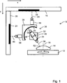
Die in
Ferner weist die Messeinrichtung
Der Halter
Der zwei entgegengesetzt ausgerichtete Abstandssensoren
Die beiden Sensoren
Der Sensor
Indem der zweite Abstandssensor
Erfährt der Sensor
Die Position des Halters
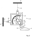
Die Ausrichtung des Abstandsmessers
Der zu dem vorgegebenen Winkel tatsächlich gemessene Abstandswert
In
Die Abstandssensoren
Insbesondere der Haupt-Abstandssensor
Mit einer geeigneten Auswerteelektronik, wie sie zum Beispiel aus der
Es wird schließlich darauf hingewiesen, dass die Anzahl und Art der hier beschriebenen Laser-Lichtquellen sowie die Anordnung einzelner Detektoren nur beispielhaft gezeigt sind. Im Rahmen der Erfindung können vielfältigste Modifikationen hinsichtlich der Art und Anzahl sowie der faseroptischen Kopplung einzelner Lichtquellen und Detektoren vorgenommen werden.It is finally pointed out that the number and type of the laser light sources described here, as well as the arrangement of individual detectors, are shown by way of example only. Within the scope of the invention, the most varied modifications can be made with regard to the type and number as well as the fiber-optic coupling of individual light sources and detectors.
BezugszeichenlisteLIST OF REFERENCE NUMBERS
- 1010
- Messvorrichtungmeasuring device
- 1212
- Trägercarrier
- 1414
- Objektobject
- 1616
- Drehachseaxis of rotation
- 1818
- Referenzobjektreference object
- 2020
- Referenzobjektreference object
- 2222
- Referenzflächereference surface
- 2424
- Referenzflächereference surface
- 2626
- Halterholder
- 2828
- Referenzkörperreference body
- 3030
- Referenzflächereference surface
- 3232
- Lagercamp
- 3434
- Abstandssensordistance sensor
- 3636
- Abstandssensordistance sensor
- 3838
- Abstanddistance
- 4040
- Abstanddistance
- 4242
- Winkelangle
- 4444
- Abstanddistance
- 4646
- Abstanddistance
- 4848
- Drehachseaxis of rotation
- 5050
- Messkopfprobe
- 5252
- Messpunktmeasuring point
- 5454
- Messpunktmeasuring point
- 5656
- Abstandssensordistance sensor
- 5858
- Abstandssensordistance sensor
- 6060
- Lichtquellelight source
- 6262
- Lichtquellelight source
- 6464
- Lichtquellelight source
- 6666
- Lichtquellelight source
- 7070
- Detektordetector
- 7272
- Detektordetector
- 7474
- Detektordetector
- 7676
- Detektordetector
- 7878
- Detektordetector
- 8080
- Detektordetector
- 8282
- Detektordetector
- 8484
- Auswerteeinheitevaluation
- 8686
- Fasersplitter, DemultiplexerFiber splitter, demultiplexer
ZITATE ENTHALTEN IN DER BESCHREIBUNG QUOTES INCLUDE IN THE DESCRIPTION
Diese Liste der vom Anmelder aufgeführten Dokumente wurde automatisiert erzeugt und ist ausschließlich zur besseren Information des Lesers aufgenommen. Die Liste ist nicht Bestandteil der deutschen Patent- bzw. Gebrauchsmusteranmeldung. Das DPMA übernimmt keinerlei Haftung für etwaige Fehler oder Auslassungen.This list of the documents listed by the applicant has been generated automatically and is included solely for the better information of the reader. The list is not part of the German patent or utility model application. The DPMA assumes no liability for any errors or omissions.
Zitierte PatentliteraturCited patent literature
- DE 102008033942 B3 [0003, 0029, 0053] DE 102008033942 B3 [0003, 0029, 0053]
- DE 602004004916 T2 [0004] DE 602004004916 T2 [0004]
Claims (16)
Priority Applications (5)
| Application Number | Priority Date | Filing Date | Title |
|---|---|---|---|
| DE102011011065A DE102011011065B4 (en) | 2011-02-11 | 2011-02-11 | Method and device for the high-precision measurement of surfaces |
| EP12705788.3A EP2673590B1 (en) | 2011-02-11 | 2012-02-08 | Method and device for measuring surfaces in a highly precise manner |
| US13/982,455 US8736850B2 (en) | 2011-02-11 | 2012-02-08 | Method and device for measuring surfaces in a highly precise manner |
| PCT/EP2012/000575 WO2012107225A1 (en) | 2011-02-11 | 2012-02-08 | Method and device for measuring surfaces in a highly precise manner |
| JP2013552884A JP5784150B2 (en) | 2011-02-11 | 2012-02-08 | Method and apparatus for measuring surface with high accuracy |
Applications Claiming Priority (1)
| Application Number | Priority Date | Filing Date | Title |
|---|---|---|---|
| DE102011011065A DE102011011065B4 (en) | 2011-02-11 | 2011-02-11 | Method and device for the high-precision measurement of surfaces |
Publications (2)
| Publication Number | Publication Date |
|---|---|
| DE102011011065A1 true DE102011011065A1 (en) | 2012-08-16 |
| DE102011011065B4 DE102011011065B4 (en) | 2013-04-04 |
Family
ID=45757370
Family Applications (1)
| Application Number | Title | Priority Date | Filing Date |
|---|---|---|---|
| DE102011011065A Expired - Fee Related DE102011011065B4 (en) | 2011-02-11 | 2011-02-11 | Method and device for the high-precision measurement of surfaces |
Country Status (5)
| Country | Link |
|---|---|
| US (1) | US8736850B2 (en) |
| EP (1) | EP2673590B1 (en) |
| JP (1) | JP5784150B2 (en) |
| DE (1) | DE102011011065B4 (en) |
| WO (1) | WO2012107225A1 (en) |
Cited By (5)
| Publication number | Priority date | Publication date | Assignee | Title |
|---|---|---|---|---|
| DE102012017015A1 (en) * | 2012-08-20 | 2014-02-20 | Luphos Gmbh | Method and device for the high-precision measurement of surfaces |
| WO2015180826A3 (en) * | 2014-05-19 | 2016-03-03 | Luphos Gmbh | Device and method for geometrically measuring an object |
| EP3835717A1 (en) | 2019-12-11 | 2021-06-16 | Taylor Hobson Limited | Wavelength reference unit and interferometric measuring device |
| EP3896386A1 (en) | 2020-04-16 | 2021-10-20 | Taylor Hobson Limited | Interferometric measuring device |
| DE102023209643A1 (en) | 2023-09-29 | 2025-04-03 | Carl Zeiss Smt Gmbh | Measuring device, method for operating the measuring device |
Families Citing this family (5)
| Publication number | Priority date | Publication date | Assignee | Title |
|---|---|---|---|---|
| DE102014007203A1 (en) * | 2014-05-19 | 2015-11-19 | Luphos Gmbh | Device and method for geometric measurement of an object |
| DE102014007202A1 (en) | 2014-05-19 | 2015-11-19 | Luphos Gmbh | Device and method for determining the position and position of an object |
| EP3492859A1 (en) | 2017-12-04 | 2019-06-05 | Taylor Hobson Limited | Device and method for geometrically measuring an object |
| EP3608626A1 (en) | 2018-08-10 | 2020-02-12 | Taylor Hobson Limited | Device and method for geometrically measuring an object |
| GB2622565B (en) | 2022-07-15 | 2025-05-28 | Taylor Hobson Ltd | A collision protection apparatus |
Citations (3)
| Publication number | Priority date | Publication date | Assignee | Title |
|---|---|---|---|---|
| DE102006019623B4 (en) * | 2005-04-30 | 2007-05-03 | Hexagon Metrology Gmbh | Method for roundness measurement on a workpiece and coordinate measuring machine for performing a roundness measurement on a workpiece |
| DE602004004916T2 (en) | 2003-09-29 | 2007-11-22 | Nederlandse Organisatie Voor Toegepast-Natuurwetenschappelijk Onderzoek Tno | OPTICAL FREE-FORM SURFACE MEASURING DEVICE AND METHOD |
| DE102008033942B3 (en) | 2008-07-18 | 2010-04-08 | Luphos Gmbh | Fiber-optic multi-wavelength interferometer (MWLI) for the absolute measurement of distances and topologies of surfaces at a large working distance |
Family Cites Families (5)
| Publication number | Priority date | Publication date | Assignee | Title |
|---|---|---|---|---|
| US6008901A (en) | 1997-08-22 | 1999-12-28 | Canon Kabushiki Kaisha | Shape measuring heterodyne interferometer with multiplexed photodetector aaray or inclined probe head |
| FR2862408B1 (en) * | 2003-11-14 | 2006-03-24 | Sagem | OPTICAL IMAGING DEVICE FOR THE FORMATION OF AN IMAGE OF DIGITAL IMPRESSIONS |
| EP1992905A1 (en) * | 2007-05-16 | 2008-11-19 | Nederlandse Organisatie voor toegepast- natuurwetenschappelijk onderzoek TNO | Optical sensor with tilt error correction |
| JP2010204094A (en) * | 2009-02-05 | 2010-09-16 | Mitsutoyo Corp | Noncontact shape measuring machine and measuring method |
| JP5486379B2 (en) * | 2009-10-01 | 2014-05-07 | キヤノン株式会社 | Surface shape measuring device |
-
2011
- 2011-02-11 DE DE102011011065A patent/DE102011011065B4/en not_active Expired - Fee Related
-
2012
- 2012-02-08 US US13/982,455 patent/US8736850B2/en active Active
- 2012-02-08 WO PCT/EP2012/000575 patent/WO2012107225A1/en not_active Ceased
- 2012-02-08 EP EP12705788.3A patent/EP2673590B1/en active Active
- 2012-02-08 JP JP2013552884A patent/JP5784150B2/en active Active
Patent Citations (3)
| Publication number | Priority date | Publication date | Assignee | Title |
|---|---|---|---|---|
| DE602004004916T2 (en) | 2003-09-29 | 2007-11-22 | Nederlandse Organisatie Voor Toegepast-Natuurwetenschappelijk Onderzoek Tno | OPTICAL FREE-FORM SURFACE MEASURING DEVICE AND METHOD |
| DE102006019623B4 (en) * | 2005-04-30 | 2007-05-03 | Hexagon Metrology Gmbh | Method for roundness measurement on a workpiece and coordinate measuring machine for performing a roundness measurement on a workpiece |
| DE102008033942B3 (en) | 2008-07-18 | 2010-04-08 | Luphos Gmbh | Fiber-optic multi-wavelength interferometer (MWLI) for the absolute measurement of distances and topologies of surfaces at a large working distance |
Cited By (12)
| Publication number | Priority date | Publication date | Assignee | Title |
|---|---|---|---|---|
| DE102012017015A1 (en) * | 2012-08-20 | 2014-02-20 | Luphos Gmbh | Method and device for the high-precision measurement of surfaces |
| WO2014029495A1 (en) * | 2012-08-20 | 2014-02-27 | Luphos Gmbh | Method and device for highly-precise measurement of surfaces |
| DE102012017015B4 (en) * | 2012-08-20 | 2015-03-19 | Luphos Gmbh | Method and device for the high-precision measurement of surfaces |
| JP2015529818A (en) * | 2012-08-20 | 2015-10-08 | ルーフオス・ゲゼルシヤフト・ミツト・ベシユレンクテル・ハフツング | Method and device for measuring surfaces very accurately |
| US9772182B2 (en) | 2012-08-20 | 2017-09-26 | Luphos Gmbh | Method and device for highly-precise measurement of surfaces |
| WO2015180826A3 (en) * | 2014-05-19 | 2016-03-03 | Luphos Gmbh | Device and method for geometrically measuring an object |
| US10371511B2 (en) | 2014-05-19 | 2019-08-06 | Taylor Hobson Ltd. | Device and method for geometrically measuring an object |
| EP3835717A1 (en) | 2019-12-11 | 2021-06-16 | Taylor Hobson Limited | Wavelength reference unit and interferometric measuring device |
| WO2021116172A1 (en) | 2019-12-11 | 2021-06-17 | Taylor Hobson Ltd. | Wavelength reference unit and interferometric measuring device |
| EP3896386A1 (en) | 2020-04-16 | 2021-10-20 | Taylor Hobson Limited | Interferometric measuring device |
| WO2021209478A1 (en) | 2020-04-16 | 2021-10-21 | Taylor Hobson Ltd. | Interferometric measuring device |
| DE102023209643A1 (en) | 2023-09-29 | 2025-04-03 | Carl Zeiss Smt Gmbh | Measuring device, method for operating the measuring device |
Also Published As
| Publication number | Publication date |
|---|---|
| JP5784150B2 (en) | 2015-09-24 |
| JP2014508292A (en) | 2014-04-03 |
| US20130308139A1 (en) | 2013-11-21 |
| DE102011011065B4 (en) | 2013-04-04 |
| EP2673590B1 (en) | 2019-10-02 |
| US8736850B2 (en) | 2014-05-27 |
| EP2673590A1 (en) | 2013-12-18 |
| WO2012107225A1 (en) | 2012-08-16 |
Similar Documents
| Publication | Publication Date | Title |
|---|---|---|
| DE102011011065B4 (en) | Method and device for the high-precision measurement of surfaces | |
| DE3886767T3 (en) | CALIBRATION SYSTEM FOR COORDINATE MEASURING DEVICE. | |
| DE102012111008B4 (en) | Optical measuring method and optical measuring device for detecting a surface topography | |
| EP2093537B1 (en) | Process and device for the determination of the alignment of two rotatable machine parts | |
| DE102015217637C5 (en) | Operation of a confocal white light sensor on a coordinate measuring machine and arrangement | |
| EP2762832B1 (en) | Optical single-point measurement | |
| DE102014007203A1 (en) | Device and method for geometric measurement of an object | |
| DE102011012611B4 (en) | Method and device for non-contact measurement of an angle | |
| EP3146293B1 (en) | Device and method for geometrically measuring an object | |
| EP3101385A1 (en) | Device and method for detecting surface topographies | |
| EP3435032B1 (en) | Optical roughness sensor for a coordinate measuring machine | |
| DE102012017015B4 (en) | Method and device for the high-precision measurement of surfaces | |
| DE102007043803A1 (en) | Device and method for determining the spatial position of moving elements of a coordinate measuring machine | |
| DE112018004038T5 (en) | Measurement of the position of objects in space | |
| EP1585938A1 (en) | Optical measuring process and precision measuring machine for determining the deviations from ideal shape of technically polished surfaces | |
| DE10317826B4 (en) | Method and device for interferometric measurement | |
| EP3833930B1 (en) | Device and method for geometrically measuring an object | |
| DE102019134939B4 (en) | Device and method for detecting the position of a body, as well as coordinate measuring machine | |
| DE102008062458A1 (en) | Laser-based measuring device for use during manufacturing process in machine and equipment construction, has polarizing filter provided in radiation, where adjustment of plane corresponds to direction of linear polarization of radiation | |
| DE102024113613A1 (en) | Device and method for measuring wafers | |
| DE102004013521B4 (en) | Curved profile measuring machine has contactless probe using common ray path and confocal imaging system with suitable coated beam splitter | |
| DE102020124704A1 (en) | Device and method for detecting a spatial position of a body | |
| DE202015009405U1 (en) | Arrangement for calibrating a measuring device | |
| DE102017003257A1 (en) | Method for detecting position deviations of an axis system of a machine tool and apparatus for carrying out this method |
Legal Events
| Date | Code | Title | Description |
|---|---|---|---|
| R012 | Request for examination validly filed | ||
| R016 | Response to examination communication | ||
| R016 | Response to examination communication | ||
| R018 | Grant decision by examination section/examining division | ||
| R020 | Patent grant now final |
Effective date: 20130705 |
|
| R081 | Change of applicant/patentee |
Owner name: TAYLOR HOBSON LTD., GB Free format text: FORMER OWNER: LUPHOS GMBH, 55130 MAINZ, DE |
|
| R082 | Change of representative |
Representative=s name: QUERMANN STURM WEILNAU PATENTANWAELTE PARTNERS, DE |
|
| R119 | Application deemed withdrawn, or ip right lapsed, due to non-payment of renewal fee |