DE102010052704A1 - Ceramic assembly for use as e.g. gas-to-gas humidifier in anode gas branch in fuel cell system, has coupling device formed for coupling and decoupling of fluids into groups of flow channels of two ceramic components - Google Patents
Ceramic assembly for use as e.g. gas-to-gas humidifier in anode gas branch in fuel cell system, has coupling device formed for coupling and decoupling of fluids into groups of flow channels of two ceramic components Download PDFInfo
- Publication number
- DE102010052704A1 DE102010052704A1 DE102010052704A DE102010052704A DE102010052704A1 DE 102010052704 A1 DE102010052704 A1 DE 102010052704A1 DE 102010052704 A DE102010052704 A DE 102010052704A DE 102010052704 A DE102010052704 A DE 102010052704A DE 102010052704 A1 DE102010052704 A1 DE 102010052704A1
- Authority
- DE
- Germany
- Prior art keywords
- flow channels
- ceramic
- group
- gas
- fluids
- Prior art date
- Legal status (The legal status is an assumption and is not a legal conclusion. Google has not performed a legal analysis and makes no representation as to the accuracy of the status listed.)
- Withdrawn
Links
- 239000000919 ceramic Substances 0.000 title claims abstract description 129
- 230000008878 coupling Effects 0.000 title claims abstract description 50
- 238000010168 coupling process Methods 0.000 title claims abstract description 50
- 238000005859 coupling reaction Methods 0.000 title claims abstract description 50
- 239000012530 fluid Substances 0.000 title claims abstract description 42
- 239000000446 fuel Substances 0.000 title claims description 16
- 238000000926 separation method Methods 0.000 claims abstract description 33
- 238000007789 sealing Methods 0.000 claims description 22
- 239000007788 liquid Substances 0.000 abstract description 3
- 239000007789 gas Substances 0.000 description 15
- 238000000034 method Methods 0.000 description 5
- 238000012546 transfer Methods 0.000 description 5
- 230000008901 benefit Effects 0.000 description 4
- 239000011159 matrix material Substances 0.000 description 4
- 239000003570 air Substances 0.000 description 3
- 230000000712 assembly Effects 0.000 description 3
- 238000000429 assembly Methods 0.000 description 3
- 230000003750 conditioning effect Effects 0.000 description 2
- 238000013461 design Methods 0.000 description 2
- 238000011161 development Methods 0.000 description 2
- 230000008569 process Effects 0.000 description 2
- BUHVIAUBTBOHAG-FOYDDCNASA-N (2r,3r,4s,5r)-2-[6-[[2-(3,5-dimethoxyphenyl)-2-(2-methylphenyl)ethyl]amino]purin-9-yl]-5-(hydroxymethyl)oxolane-3,4-diol Chemical compound COC1=CC(OC)=CC(C(CNC=2C=3N=CN(C=3N=CN=2)[C@H]2[C@@H]([C@H](O)[C@@H](CO)O2)O)C=2C(=CC=CC=2)C)=C1 BUHVIAUBTBOHAG-FOYDDCNASA-N 0.000 description 1
- 239000012080 ambient air Substances 0.000 description 1
- 229910010293 ceramic material Inorganic materials 0.000 description 1
- 230000001143 conditioned effect Effects 0.000 description 1
- 229910052878 cordierite Inorganic materials 0.000 description 1
- 230000001419 dependent effect Effects 0.000 description 1
- JSKIRARMQDRGJZ-UHFFFAOYSA-N dimagnesium dioxido-bis[(1-oxido-3-oxo-2,4,6,8,9-pentaoxa-1,3-disila-5,7-dialuminabicyclo[3.3.1]nonan-7-yl)oxy]silane Chemical compound [Mg++].[Mg++].[O-][Si]([O-])(O[Al]1O[Al]2O[Si](=O)O[Si]([O-])(O1)O2)O[Al]1O[Al]2O[Si](=O)O[Si]([O-])(O1)O2 JSKIRARMQDRGJZ-UHFFFAOYSA-N 0.000 description 1
- 230000000694 effects Effects 0.000 description 1
- 238000004519 manufacturing process Methods 0.000 description 1
- 239000000463 material Substances 0.000 description 1
- 239000007769 metal material Substances 0.000 description 1
- 229910044991 metal oxide Inorganic materials 0.000 description 1
- 150000004706 metal oxides Chemical class 0.000 description 1
- 238000000465 moulding Methods 0.000 description 1
- TWNQGVIAIRXVLR-UHFFFAOYSA-N oxo(oxoalumanyloxy)alumane Chemical compound O=[Al]O[Al]=O TWNQGVIAIRXVLR-UHFFFAOYSA-N 0.000 description 1
- RVTZCBVAJQQJTK-UHFFFAOYSA-N oxygen(2-);zirconium(4+) Chemical compound [O-2].[O-2].[Zr+4] RVTZCBVAJQQJTK-UHFFFAOYSA-N 0.000 description 1
- 230000009467 reduction Effects 0.000 description 1
- HBMJWWWQQXIZIP-UHFFFAOYSA-N silicon carbide Chemical compound [Si+]#[C-] HBMJWWWQQXIZIP-UHFFFAOYSA-N 0.000 description 1
- 229910010271 silicon carbide Inorganic materials 0.000 description 1
- 238000005245 sintering Methods 0.000 description 1
- 238000012549 training Methods 0.000 description 1
- 230000007704 transition Effects 0.000 description 1
- 229910001928 zirconium oxide Inorganic materials 0.000 description 1
Images




Classifications
-
- H—ELECTRICITY
- H01—ELECTRIC ELEMENTS
- H01M—PROCESSES OR MEANS, e.g. BATTERIES, FOR THE DIRECT CONVERSION OF CHEMICAL ENERGY INTO ELECTRICAL ENERGY
- H01M8/00—Fuel cells; Manufacture thereof
- H01M8/04—Auxiliary arrangements, e.g. for control of pressure or for circulation of fluids
- H01M8/04082—Arrangements for control of reactant parameters, e.g. pressure or concentration
- H01M8/04089—Arrangements for control of reactant parameters, e.g. pressure or concentration of gaseous reactants
- H01M8/04119—Arrangements for control of reactant parameters, e.g. pressure or concentration of gaseous reactants with simultaneous supply or evacuation of electrolyte; Humidifying or dehumidifying
- H01M8/04156—Arrangements for control of reactant parameters, e.g. pressure or concentration of gaseous reactants with simultaneous supply or evacuation of electrolyte; Humidifying or dehumidifying with product water removal
-
- F—MECHANICAL ENGINEERING; LIGHTING; HEATING; WEAPONS; BLASTING
- F28—HEAT EXCHANGE IN GENERAL
- F28F—DETAILS OF HEAT-EXCHANGE AND HEAT-TRANSFER APPARATUS, OF GENERAL APPLICATION
- F28F21/00—Constructions of heat-exchange apparatus characterised by the selection of particular materials
- F28F21/04—Constructions of heat-exchange apparatus characterised by the selection of particular materials of ceramic; of concrete; of natural stone
-
- F—MECHANICAL ENGINEERING; LIGHTING; HEATING; WEAPONS; BLASTING
- F28—HEAT EXCHANGE IN GENERAL
- F28F—DETAILS OF HEAT-EXCHANGE AND HEAT-TRANSFER APPARATUS, OF GENERAL APPLICATION
- F28F9/00—Casings; Header boxes; Auxiliary supports for elements; Auxiliary members within casings
- F28F9/26—Arrangements for connecting different sections of heat-exchange elements, e.g. of radiators
-
- H—ELECTRICITY
- H01—ELECTRIC ELEMENTS
- H01M—PROCESSES OR MEANS, e.g. BATTERIES, FOR THE DIRECT CONVERSION OF CHEMICAL ENERGY INTO ELECTRICAL ENERGY
- H01M8/00—Fuel cells; Manufacture thereof
- H01M8/04—Auxiliary arrangements, e.g. for control of pressure or for circulation of fluids
- H01M8/04007—Auxiliary arrangements, e.g. for control of pressure or for circulation of fluids related to heat exchange
- H01M8/04067—Heat exchange or temperature measuring elements, thermal insulation, e.g. heat pipes, heat pumps, fins
-
- H—ELECTRICITY
- H01—ELECTRIC ELEMENTS
- H01M—PROCESSES OR MEANS, e.g. BATTERIES, FOR THE DIRECT CONVERSION OF CHEMICAL ENERGY INTO ELECTRICAL ENERGY
- H01M8/00—Fuel cells; Manufacture thereof
- H01M8/04—Auxiliary arrangements, e.g. for control of pressure or for circulation of fluids
- H01M8/04082—Arrangements for control of reactant parameters, e.g. pressure or concentration
- H01M8/04089—Arrangements for control of reactant parameters, e.g. pressure or concentration of gaseous reactants
- H01M8/04119—Arrangements for control of reactant parameters, e.g. pressure or concentration of gaseous reactants with simultaneous supply or evacuation of electrolyte; Humidifying or dehumidifying
- H01M8/04126—Humidifying
-
- H—ELECTRICITY
- H01—ELECTRIC ELEMENTS
- H01M—PROCESSES OR MEANS, e.g. BATTERIES, FOR THE DIRECT CONVERSION OF CHEMICAL ENERGY INTO ELECTRICAL ENERGY
- H01M8/00—Fuel cells; Manufacture thereof
- H01M8/04—Auxiliary arrangements, e.g. for control of pressure or for circulation of fluids
- H01M8/04082—Arrangements for control of reactant parameters, e.g. pressure or concentration
- H01M8/04089—Arrangements for control of reactant parameters, e.g. pressure or concentration of gaseous reactants
- H01M8/04119—Arrangements for control of reactant parameters, e.g. pressure or concentration of gaseous reactants with simultaneous supply or evacuation of electrolyte; Humidifying or dehumidifying
- H01M8/04126—Humidifying
- H01M8/04141—Humidifying by water containing exhaust gases
-
- F—MECHANICAL ENGINEERING; LIGHTING; HEATING; WEAPONS; BLASTING
- F28—HEAT EXCHANGE IN GENERAL
- F28F—DETAILS OF HEAT-EXCHANGE AND HEAT-TRANSFER APPARATUS, OF GENERAL APPLICATION
- F28F2280/00—Mounting arrangements; Arrangements for facilitating assembling or disassembling of heat exchanger parts
- F28F2280/06—Adapter frames, e.g. for mounting heat exchanger cores on other structure and for allowing fluidic connections
-
- Y—GENERAL TAGGING OF NEW TECHNOLOGICAL DEVELOPMENTS; GENERAL TAGGING OF CROSS-SECTIONAL TECHNOLOGIES SPANNING OVER SEVERAL SECTIONS OF THE IPC; TECHNICAL SUBJECTS COVERED BY FORMER USPC CROSS-REFERENCE ART COLLECTIONS [XRACs] AND DIGESTS
- Y02—TECHNOLOGIES OR APPLICATIONS FOR MITIGATION OR ADAPTATION AGAINST CLIMATE CHANGE
- Y02E—REDUCTION OF GREENHOUSE GAS [GHG] EMISSIONS, RELATED TO ENERGY GENERATION, TRANSMISSION OR DISTRIBUTION
- Y02E60/00—Enabling technologies; Technologies with a potential or indirect contribution to GHG emissions mitigation
- Y02E60/30—Hydrogen technology
- Y02E60/50—Fuel cells
Landscapes
- Engineering & Computer Science (AREA)
- Chemical Kinetics & Catalysis (AREA)
- Manufacturing & Machinery (AREA)
- Sustainable Development (AREA)
- Sustainable Energy (AREA)
- Chemical & Material Sciences (AREA)
- Life Sciences & Earth Sciences (AREA)
- Electrochemistry (AREA)
- General Chemical & Material Sciences (AREA)
- Physics & Mathematics (AREA)
- Thermal Sciences (AREA)
- Mechanical Engineering (AREA)
- General Engineering & Computer Science (AREA)
- Ceramic Engineering (AREA)
- Physical Or Chemical Processes And Apparatus (AREA)
Abstract
Description
Die Erfindung betrifft eine Keramikbaugruppe mit mindestens einem ersten und einem zweiten Keramikbauteil, wobei die Keramikbauteile jeweils eine Mehrzahl von Strömungskanälen zur Führung von Fluiden aufweisen, mit einer Kopplungseinrichtung, welche eine erste Gruppe der Strömungskanälen des ersten Keramikbauteils mit einer ersten Gruppe der Strömungskanäle des zweiten Keramikbauteils strömungstechnisch verbindet. Die Erfindung betrifft auch ein Brennstoffzellensystem mit dieser Keramikbaugruppe.The invention relates to a ceramic assembly having at least a first and a second ceramic component, wherein the ceramic components each have a plurality of flow channels for guiding fluids, with a coupling device which a first group of the flow channels of the first ceramic component with a first group of the flow channels of the second ceramic component fluidically connects. The invention also relates to a fuel cell system with this ceramic assembly.
Keramikbaugruppen mit Strömungskanälen zur Führung von Fluiden werden beispielsweise bei Brennstoffzellensystemen als Gas-zu-Gas-Befeuchter oder Wärmetauscher eingesetzt. Hier erfüllt die Keramikbaugruppe die Aufgabe, Kathodengas oder Anodengas für die Brennstoffzellen des Brennstoffzellensystems hinsichtlich der Temperatur oder einem Feuchtigkeitsgehalt zu konditionieren. Die Konditionierung erfolgt durch Wärme- oder Feuchtigkeitsübertrag von einem Fluid zu einem anderen.Ceramic assemblies with flow channels for guiding fluids are used, for example, in fuel cell systems as a gas-to-gas humidifier or heat exchanger. Here, the ceramic assembly fulfills the task of conditioning cathode gas or anode gas for the fuel cells of the fuel cell system in terms of temperature or moisture content. The conditioning is carried out by heat or moisture transfer from one fluid to another.
Aus der
Der Erfindung liegt die Aufgabe zugrunde, eine anpassbare Keramikbaugruppe sowie ein Brennstoffzellensystem mit dieser Keramikbaugruppe vorzuschlagen.The invention has for its object to propose an adaptable ceramic assembly and a fuel cell system with this ceramic assembly.
Diese Aufgabe wird durch eine Keramikbaugruppe mit den Merkmalen des Anspruches 1 sowie durch ein Brennstoffzellensystem mit den Merkmalen des Anspruches 12 gelöst. Bevorzugte oder vorteilhafte Ausführungsformen der Erfindung ergeben sich aus den Unteransprüchen, der nachfolgenden Beschreibung sowie den beigefügten Figuren.This object is achieved by a ceramic assembly having the features of claim 1 and by a fuel cell system having the features of
Ein Gegenstand der Erfindung betrifft somit eine Keramikbaugruppe, welche mindestens ein erstes und ein zweites Keramikbauteil umfasst. Bei dem Keramikmaterial der Keramikbauteile kann es sich um eine beliebige Art der Keramik, insbesondere der technischen Keramik, handeln, so zum Beispiel eine Keramik aus Metalloxiden, insbesondere Aluminiumoxid, Zirkonoxid oder Cordierit, oder auch aus Siliziumkarbid. Besonders bevorzugt sind die Keramikbauteile einstückig und/oder als Monolith realisiert. Diese Bauart ist besonders kostengünstig zu fertigen.An object of the invention thus relates to a ceramic assembly comprising at least a first and a second ceramic component. The ceramic material of the ceramic components may be any type of ceramic, in particular technical ceramics, such as a ceramic of metal oxides, in particular aluminum oxide, zirconium oxide or cordierite, or of silicon carbide. Particularly preferably, the ceramic components are in one piece and / or implemented as a monolith. This design is particularly inexpensive to manufacture.
Sowohl in dem ersten Keramikbauteil als auch in dem zweiten Keramikbauteil ist eine Vielzahl von Strömungskanälen eingebracht. Die Strömungskanäle sind bei einer möglichen Ausbildung geradlinig verlaufend ausgebildet, bei anderen Ausführungsformen ist es auch möglich, dass diese kurvenartig oder gewinkelt verlaufen. Die Strömungskanäle sind insbesondere ausgebildet, um Fluide, zum Beispiel Gase oder Flüssigkeiten, zu führen. Insbesondere sind die Strömungskanäle als Mikrokanäle mit einem typischen Durchmesser kleiner als 2 mm realisiert.Both in the first ceramic component and in the second ceramic component, a plurality of flow channels is introduced. The flow channels are formed in a straight line running in a possible training, in other embodiments, it is also possible that these run in a curve or angled. The flow channels are in particular designed to guide fluids, for example gases or liquids. In particular, the flow channels are realized as microchannels with a typical diameter smaller than 2 mm.
Die Keramikbauteile sind vorzugsweise porös ausgebildet, so dass Feuchtigkeit von einem ersten Strömungskanal in einen zweiten, insbesondere benachbarten oder angrenzenden Strömungskanal übergehen kann.The ceramic components are preferably porous, so that moisture can pass from a first flow channel into a second, in particular adjacent or adjacent flow channel.
Eine Kopplungseinrichtung ist vorgesehen, die eine erste Gruppe der Strömungskanäle des ersten Keramikbauteils mit einer ersten Gruppe der Strömungskanäle der zweiten Keramikbauteile strömungstechnisch verbindet oder koppelt. Damit können Fluide, welche in Strömungskanälen der ersten Gruppe des ersten Keramikbauteils geführt werden, über die Kopplungseinrichtung in die Strömungskanäle der ersten Gruppe des zweiten Keramikbauteils weitergeführt werden.A coupling device is provided, which fluidly connects or couples a first group of the flow channels of the first ceramic component with a first group of the flow channels of the second ceramic components. Thus, fluids which are guided in flow channels of the first group of the first ceramic component can be continued via the coupling device into the flow channels of the first group of the second ceramic component.
Im Rahmen der Erfindung wird vorgeschlagen, dass die Kopplungseinrichtung zur Ein- und/oder Auskopplung von Fluiden in eine zweite Gruppe der Strömungskanäle des ersten und/oder des zweiten Keramikbauteils ausgebildet ist. Die Kopplungseinrichtung bildet somit ein Interface zwischen zwei Keramikbauteilen, das es ermöglicht, ein Medium aus der zweiten Gruppe der Strömungskanäle des ersten und/oder zweiten Keramikbauteils zu separieren und zum Beispiel über einen Sammler den Keramikbauteilen zu- bzw. abzuführen. Mit der Erfindung ist es somit möglich, dass ein erstes Fluid durch die erste Gruppe von Strömungskanälen durch die Keramikbaugruppe durchgeführt wird und ein zweites Fluid über die Kopplungseinrichtung in die zweite Gruppe der Strömungskanäle ein- bzw. abgeführt werden kann. Insbesondere ist an jedem Ende der Keramikbauteile eine derartige Kopplungseinrichtung oder – beispielsweise endseitig – eine andere Einrichtung zur Ein- und/oder Auskopplung von Fluiden in die zweite Gruppe der Strömungskanäle des ersten und/oder des zweiten Keramikbausteils angeordnet.In the context of the invention it is proposed that the coupling device is designed for coupling and / or decoupling fluids into a second group of the flow channels of the first and / or the second ceramic component. The coupling device thus forms an interface between two ceramic components, which makes it possible to separate a medium from the second group of flow channels of the first and / or second ceramic component and, for example via a collector to the ceramic components supply or dissipate. With the invention, it is thus possible that a first fluid through the first group of flow channels through the ceramic assembly is performed and a second fluid via the coupling device in the second group of the flow channels can be introduced or removed. In particular, at each end of the ceramic components, such a coupling device or - for example, end side - arranged another means for coupling and / or decoupling fluids in the second group of flow channels of the first and / or the second ceramic component.
Durch die Erfindung ergibt sich der Vorteil, dass bei gekoppelten Keramikbauteilen in verschiedenen Keramikbauteilen das Fluid in der zweiten Gruppe der Strömungskanäle beliebig gewählt werden kann. So können in unterschiedlichen Keramikbauteilen unterschiedliche Fluide und/oder Fluide mit unterschiedlichen Parametern, wie z. B. Temperatur, Druck, Feuchtigkeitsgehalt und/oder Strömungsrichtung, in der zweiten Gruppe der Strömungskanäle geführt werden. Durch die erfindungsgemäße Keramikbaugruppe können somit Fluide wahlfrei eingesetzt werden.The invention provides the advantage that in coupled ceramic components in various ceramic components, the fluid in the second group of flow channels can be chosen arbitrarily. Thus, in different ceramic components different fluids and / or fluids with different parameters, such as. As temperature, pressure, moisture content and / or flow direction, in the second group of the flow channels be guided. The ceramic assembly according to the invention thus fluids can be used optionally.
Bei mehr als zwei Keramikbauteilen ist es auch möglich, mehrere Kopplungseinrichtungen so auszuführen, dass eine erste Kopplungseinrichtung zur Ein- und/oder Auskopplung von Fluiden in die zweite Gruppe der Strömungskanäle ausgebildet ist und die Fluide in der ersten Gruppe der Strömungskanäle durchführt und eine weitere Kopplungseinrichtung gegengleich aufgebaut ist und zur Ein- und/oder Auskopplung von Fluiden in die erste Gruppe der Strömungskanäle ausgebildet ist und die Fluide in der zweiten Gruppe der Strömungskanäle durchführt.In the case of more than two ceramic components, it is also possible to design a plurality of coupling devices such that a first coupling device is designed for coupling and / or decoupling fluids into the second group of flow channels and carries out the fluids in the first group of flow channels and a further coupling device is constructed opposite and is designed for coupling and / or decoupling fluids in the first group of flow channels and performs the fluids in the second group of flow channels.
Bei einer besonders bevorzugten Ausführungsform werden die Strömungskanäle der ersten Gruppe des ersten Keramikbauteils mit den Strömungskanälen der ersten Gruppe des zweiten Keramikbauteils selektiv verbunden. Eine selektive Verbindung erfolgt insbesondere dadurch, dass Strömungskanäle n:n verbunden werden, wobei n eine ganze natürliche Zahl darstellt. Im einfachsten und bevorzugten Fall werden die Strömungskanäle 1:1 verbunden. Es ist jedoch auch möglich, die Strömungskanäle beispielsweise 2:2, 3:3 oder 4:4 zu verbinden, wobei im letztgenannten Fall es bevorzugt ist, dass die zu verbindenden Strömungskanäle quadratisch angeordnet sind. Um die Feuchtigkeitsübertragungsfläche bzw. Wärmeübertragungsfläche in als Gas-zu-Gas-Befeuchtern bzw. Wärmetauscher ausgebildeten Keramikbaugruppen zu optimieren, ist es nämlich besonders vorteilhaft, wenn die Anströmung mit Fluiden, insbesondere gasförmigen Medien, in den zwei Gruppen der Strömungskanäle abwechselnd erfolgt. Das bedeutet, dass es bevorzugt ist, dass sich in unmittelbarer Nachbarschaft eines mit einem Medium A durchströmten Strömungskanals ausschließlich Strömungskanäle befinden, die mit einem anderen Medium B durchströmt werden. Im Idealfall kann der Stoff- und/oder Wärmetransport über alle Kanalwandungen des Strömungskanals erfolgen. Bei rechteckigen oder quadratischen Kanalquerschnitten können dies bis zu vier Kanalwandungen sein.In a particularly preferred embodiment, the flow channels of the first group of the first ceramic component are selectively connected to the flow channels of the first group of the second ceramic component. In particular, a selective connection is made by connecting flow channels n: n, where n represents an integer natural number. In the simplest and preferred case, the flow channels are connected 1: 1. However, it is also possible to connect the flow channels, for example 2: 2, 3: 3 or 4: 4, wherein in the latter case it is preferred that the flow channels to be connected are arranged square. In order to optimize the moisture transfer surface or heat transfer surface in ceramic assemblies designed as gas-to-gas humidifiers or heat exchangers, it is particularly advantageous if the flow of fluids, in particular gaseous media, takes place alternately in the two groups of flow channels. This means that it is preferred that exclusively flow channels are located in the immediate vicinity of a flow channel through which a medium A flows, through which another medium B flows. Ideally, the mass and / or heat transport can take place over all channel walls of the flow channel. With rectangular or square channel cross sections, this can be up to four channel walls.
In einer bevorzugten Weiterbildung der Erfindung ist die Kopplungseinrichtung so ausgebildet, dass die Strömungskanäle der zweiten Gruppe des ersten Keramikbauteils mit einer ersten Schnittstelle und/oder die Strömungskanäle der zweiten Gruppe des zweiten Keramikbauteils mit einer zweiten Schnittstelle verbunden sind. Die Schnittstelle ist insbesondere als eine extern zugängliche Schnittstelle ausgebildet, so dass über diese Schnittstelle bzw. Schnittstellen Fluide zu- oder abgeführt werden können. Mit dieser Ausgestaltung ist es folglich möglich, am Ende eines Keramikbauteils ein Fluid in der zweiten Gruppe der Strömungskanäle ein- bzw. auszukoppeln.In a preferred development of the invention, the coupling device is designed such that the flow channels of the second group of the first ceramic component are connected to a first interface and / or the flow channels of the second group of the second ceramic component are connected to a second interface. The interface is designed, in particular, as an externally accessible interface, so that fluids can be added or removed via this interface or interfaces. With this configuration, it is consequently possible to connect or uncouple a fluid in the second group of flow channels at the end of a ceramic component.
Bei einer bevorzugten, konstruktiven Realisierung der Erfindung weist die Kopplungseinrichtung mindestens eine Separationsplatte auf, die die erste und die zweite Gruppe von Strömungskanälen trennt oder separiert. Insbesondere ist die Separationsplatte ausgebildet, gemischt oder abwechselnd angeordnete Strömungskanäle der ersten und der zweiten Gruppe zu separieren.In a preferred, constructive realization of the invention, the coupling device has at least one separation plate which separates or separates the first and the second group of flow channels. In particular, the separation plate is designed to separate mixed or alternately arranged flow channels of the first and the second group.
In einer bevorzugten Ausführungsform der Erfindung weist die Separationsplatte Verbindungsdurchbrüche auf, die insbesondere selektiv den Strömungskanälen des angrenzenden Keramikbauteils zugeordnet sind. In einer praxisnahen Ausführungsform kann vorgesehen sein, dass die Verbindungsdurchbrüche und/oder die Strömungskanäle rasterartig oder matrixartig, insbesondere in Spalten und Zeilen, angeordnet sind, wobei das Rastermaß der Strömungskanäle in dem angrenzenden Keramikbauteil und das Rastermaß der Verbindungsdurchbrüche in der Separationsplatte gleich gewählt ist. Anders ausgedrückt, werden durch die Separationsplatte die Strömungskanäle strömungstechnisch verlängert. Selbstverständlich ist auch möglich, dass sowohl die Strömungskanäle in dem Keramikbauteil als auch die Verbindungsdurchbrüche in der Separationsplatte eine andere räumliche Aufteilung haben, die jedoch eine Weiterführung der Fluide von den Strömungskanälen der ersten und der zweiten Gruppe durch die Separationsplatte erlaubt.In a preferred embodiment of the invention, the separation plate on connection openings, which are assigned in particular selectively to the flow channels of the adjacent ceramic component. In a practical embodiment it can be provided that the connection openings and / or the flow channels are arranged like a grid or matrix, in particular in columns and rows, wherein the grid dimension of the flow channels in the adjacent ceramic component and the grid dimension of the connection openings in the separation plate is chosen to be the same. In other words, the flow channels are fluidly extended by the separation plate. Of course, it is also possible that both the flow channels in the ceramic component as well as the connection openings in the separation plate have a different spatial distribution, but which allows a continuation of the fluids from the flow channels of the first and the second group through the separation plate.
In einer Weiterbildung der Erfindung umfasst die Keramikbaugruppe eine Abdichtungsplatte, die eine Mehrzahl von Öffnungen aufweist, wobei die Öffnungen deckungsgleich mit den Verbindungsdurchbrüchen der Separationsplatte angeordneten sind, die den Strömungskanälen der ersten Gruppe zugeordnet sind. Funktionell betrachtet, erlaubt die Abdichtungsplatte ein Durchfließen von Fluiden, welche in den Strömungskanälen der ersten Gruppe geführt werden.In one development of the invention, the ceramic assembly comprises a sealing plate having a plurality of openings, wherein the openings are arranged congruently with the connection openings of the separation plate, which are associated with the flow channels of the first group. Functionally, the sealing plate allows fluids to flow through it, which are guided in the flow channels of the first group.
Dagegen ist vorzugsweise vorgesehen, dass die Abdichtungsplatte für die Strömungskanäle der zweiten Gruppe eine Begrenzung eines Medienraums bildet, wobei über den Medienraum die Ein- und/oder Auskopplung von Fluiden in die zweite Gruppe der Strömungskanäle erfolgen kann. Damit bildet die Abdichtungsplatte für die Strömungskanäle der ersten Gruppe ein durchlassendes Element und für die Strömungskanäle der zweiten Gruppe ein Begrenzungselement.In contrast, it is preferably provided that the sealing plate for the flow channels of the second group forms a boundary of a media space, wherein via the media space, the input and / or decoupling of fluids in the second group of the flow channels can be done. Thus, the sealing plate forms a passage element for the flow channels of the first group and a limiting element for the flow channels of the second group.
Betrachtet man die Abdichtung und die Separationsplatte als zwei voneinander beabstandet angeordnete Platten, so wird vorzugsweise vorgeschlagen, die Verbindung zwischen den Verbindungsdurchbrüchen der Separationsplatte für die erste Gruppe von Strömungskanälen und den Öffnungen in der Abdichtungsplatte über eine Mehrzahl von Röhren oder Hohlzylindern zu realisieren. Die Röhren oder Hohlzylinder bilden somit die Verlängerungen der Strömungskanäle der ersten Gruppe. Der zwischen der Separationsplatte und der Abdichtungsplatte verbleibende Raum, welcher nicht durch die Röhren bzw. Hohlzylinder eingenommen ist, bildet einen Teil des Medienraums, über den die Ein- und/oder Auskopplung von Fluiden in die zweite Gruppe der Strömungskanäle erfolgen kann.Considering the seal and the separation plate as two spaced-apart plates, it is preferably proposed that the connection between the connection openings of the separation plate for the first group of flow channels and the openings in the sealing plate over a plurality of To realize tubes or hollow cylinders. The tubes or hollow cylinders thus form the extensions of the flow channels of the first group. The remaining space between the separation plate and the sealing plate, which is not occupied by the tubes or hollow cylinders, forms a part of the media space through which the input and / or outcoupling of fluids in the second group of flow channels can take place.
Bei einer bevorzugten Realisierung der Erfindung ist vorgesehen, dass beidseitig der Abdichtungsplatte eine Separationsplatte angeordnet ist. Damit wird erreicht, dass die Strömungskanäle der ersten Gruppe durch die Kopplungseinrichtung durchgeschleift werden und dass beidseitig zu der Abdichtungsplatte ein Medienraum (mit-)gebildet wird, der die Ein- und/oder Auskopplung von Fluiden in die zweite Gruppe des ersten Keramikbauteils bzw. des zweiten Keramikbauteils ermöglicht.In a preferred embodiment of the invention, it is provided that a separation plate is arranged on both sides of the sealing plate. This ensures that the flow channels of the first group are looped through the coupling device and that on both sides of the sealing plate a media space (mit-) is formed, the input and / or decoupling of fluids in the second group of the first ceramic component or the second ceramic component allows.
In einer bevorzugten konstruktiven Ausgestaltung der Erfindung ist der Medienraum über eine Hutze mit der Schnittstelle abgeschlossen. Die Hutze ist vorzugsweise als ein trichterförmiges Bauteil ausgebildet, welche den Medienraum zusammen mit der Abdichtungsplatte bildet. Zur Ein- und/oder Auskopplung weist die Hutze die Schnittstelle, zum Beispiel ausgebildet als ein Stutzen oder dergleichen, auf.In a preferred structural embodiment of the invention, the media space is closed by a scoop with the interface. The scoop is preferably formed as a funnel-shaped component, which forms the media space together with the sealing plate. For coupling and / or decoupling, the scoop has the interface, for example designed as a connecting piece or the like.
Bei einer besonders bevorzugten Realisierung der Erfindung ist die Keramikbaugruppe als ein Gas-zu-Gas-Befeuchter und/oder einen Wärmetauscher für ein Brennstoffzellensystem ausgebildet. In dieser Ausbildungsform zeigen sich weitere Vorteile der Erfindung: Zur Realisierung eines Gas-zu-Gas-Befeuchters oder Wärmetauschers ist es nicht mehr notwendig, einen sehr großen Keramikkörper zu verwenden, sondern der Gas-zu-Gas-Befeuchter bzw. der Wärmetauscher kann durch mindestens zwei oder mehr Keramikbauteile realisiert werden, welche über die Kopplungseinrichtung verbunden werden. Insbesondere ist es möglich, in die Strömungskanäle der zweiten Gruppe selektiv in jedem Keramikbauteil ein Fluid ein- bzw. auszukoppeln.In a particularly preferred embodiment of the invention, the ceramic assembly is designed as a gas-to-gas humidifier and / or a heat exchanger for a fuel cell system. In this embodiment, further advantages of the invention show: To realize a gas-to-gas humidifier or heat exchanger, it is no longer necessary to use a very large ceramic body, but the gas-to-gas humidifier or the heat exchanger can at least two or more ceramic components are realized, which are connected via the coupling device. In particular, it is possible to selectively inject or disengage a fluid into the flow channels of the second group in each ceramic component.
Folglich ermöglicht die Erfindung auch, dass über Kopplungseinrichtungen verbundene Keramikbauteile unterschiedliche Funktionen einnehmen. So ist es beispielsweise möglich, dass durch die erste Gruppe der Strömungskanäle das Arbeitsgas für Brennstoffzellen des Brennstoffzellensystems geführt wird und über die zweite Gruppe der Strömungskanäle im Gleich- oder Gegenstrom pro Keramikbauteil wechselnde Fluide fließen zu lassen.Consequently, the invention also makes it possible for ceramic components connected via coupling devices to assume different functions. For example, it is possible for the working gas for fuel cells of the fuel cell system to be guided through the first group of flow channels and to allow fluids flowing in cocurrent or countercurrent per ceramic component to flow through the second group of flow channels.
Darüber hinaus ist es auch möglich, keramische Bauteile mit metallischen Baugruppen zu kombinieren. Hierbei wird ein Keramikbauteil durch eine metallische Baugruppe, wie z. B. einen aus metallischen Einzelplatten geschichteten Plattenstapel, substituiert. Besonders vorteilhaft bei dieser Anordnung ist, dass eine bedarfsgerechte Werkstoffauswahl ermöglicht wird, z. B. keramische, poröse Strukturen für den Stoffaustausch (z. B. für die Befeuchtung eines Fluids) und metallische Werkstoffe mit einer sehr guten Wärmeleitfähigkeit für den Wärmeaustausch.In addition, it is also possible to combine ceramic components with metallic assemblies. Here, a ceramic component by a metallic assembly such. As a layer of metallic single plates stacked plate stack substituted. Particularly advantageous in this arrangement is that a needs-based material selection is possible, for. As ceramic, porous structures for mass transfer (eg., For the humidification of a fluid) and metallic materials with a very good thermal conductivity for heat exchange.
Ein weiterer Gegenstand der Erfindung bildet ein Brennstoffzellensystem zur Erzeugung von elektrischer Energie, insbesondere für ein Mobil, gekennzeichnet durch eine Keramikbaugruppe nach einem der vorhergehenden Ansprüche bzw. gemäß der vorhergehenden Beschreibung. Bevorzugt ist die Keramikbaugruppe als ein Gas-zu-Gas-Befeuchter und/oder ein Wärmetauscher im Anoden- oder im Kathodengaszweig ausgebildet. Bei dieser Ausgestaltung wird beispielsweise in der ersten Gruppe der Strömungskanäle die zu konditionierende Umgebungsluft zur Zuführung in Richtung der Brennstoffzellen und in der zweiten Gruppe der Strömungskanäle feuchte Abluft aus den Brennstoffzellen geführt, so dass ein Feuchtigkeitsübertrag von der Abluft zu der Zuluft erfolgen kann. Weitere Einsatzgebiete der Keramikbaugruppe sind zum Beispiel bei Wärmetauschern zu sehen.Another object of the invention is a fuel cell system for generating electrical energy, in particular for a mobile, characterized by a ceramic assembly according to one of the preceding claims or according to the preceding description. Preferably, the ceramic assembly is designed as a gas-to-gas humidifier and / or a heat exchanger in the anode or in the cathode gas branch. In this embodiment, for example, in the first group of flow channels the ambient air to be conditioned for feeding in the direction of the fuel cell and in the second group of the flow channels moist exhaust air from the fuel cells, so that a moisture transfer from the exhaust air to the supply air can take place. Further fields of application of the ceramic module can be seen, for example, in heat exchangers.
Weitere Merkmale, Vorteile und Wirkungen der Erfindung ergeben sich aus der nachfolgenden Beschreibung eines bevorzugten Ausführungsbeispiels der Erfindung sowie den beigefügten Figuren. Dabei zeigen:Further features, advantages and effects of the invention will become apparent from the following description of a preferred embodiment of the invention and the accompanying drawings. Showing:
Einander entsprechende oder gleiche Teile sind jeweils mit einander entsprechenden oder gleichen Bezugszeichen versehen. Corresponding or identical parts are each provided with the same or the same reference numerals.
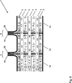
Die
Die Keramikbaugruppe
Zwischen den Keramikbauteilen
Eine erste Ausführungsform der strömungstechnischen Ankopplung der Keramikbaugruppe
Eine zweite Gruppe II der Strömungskanäle
Wie später noch erläutert wird, werden jeweils endseitig von den Keramikbauteilen
Die
Die
Die
In der Ausführungsalternative in der
Die
Nachfolgend ist eine Abdichtungsplatte
Die Strömungskanäle
Während die Öffnungen der Strömungskanäle
In der
Die Abdichtungsplatte
Nach der Abdichtungsplatte
Im zusammengebauten Zustand werden somit Strömungskanäle
Die
BezugszeichenlisteLIST OF REFERENCE NUMBERS
- 11
- Keramikbaugruppeceramic assembly
- 2a–d2a-d
- Keramikbauteileceramic components
- 33
- Strömungskanäleflow channels
- 44
- Kopplungseinrichtungencoupling devices
- 5a–b5a-b
- Schnittstelleninterfaces
- 66
- Medienräumemedia rooms
- 77
- Hutzescoop
- 88th
- Separationsplatteseparation plate
- 99
- Abdichtungsplattesealing plate
- 1010
- VerbindungsdurchbrücheConnection breakthroughs
- 1111
- Öffnungenopenings
- 1212
- Verbindungselementefasteners
- 1313
- Fensterwindow
- 1414
- Nutgroove
ZITATE ENTHALTEN IN DER BESCHREIBUNG QUOTES INCLUDE IN THE DESCRIPTION
Diese Liste der vom Anmelder aufgeführten Dokumente wurde automatisiert erzeugt und ist ausschließlich zur besseren Information des Lesers aufgenommen. Die Liste ist nicht Bestandteil der deutschen Patent- bzw. Gebrauchsmusteranmeldung. Das DPMA übernimmt keinerlei Haftung für etwaige Fehler oder Auslassungen.This list of the documents listed by the applicant has been generated automatically and is included solely for the better information of the reader. The list is not part of the German patent or utility model application. The DPMA assumes no liability for any errors or omissions.
Zitierte PatentliteraturCited patent literature
- US 20020155328 A1 [0003] US 20020155328 A1 [0003]
Claims (12)
Priority Applications (1)
| Application Number | Priority Date | Filing Date | Title |
|---|---|---|---|
| DE102010052704A DE102010052704A1 (en) | 2010-11-26 | 2010-11-26 | Ceramic assembly for use as e.g. gas-to-gas humidifier in anode gas branch in fuel cell system, has coupling device formed for coupling and decoupling of fluids into groups of flow channels of two ceramic components |
Applications Claiming Priority (1)
| Application Number | Priority Date | Filing Date | Title |
|---|---|---|---|
| DE102010052704A DE102010052704A1 (en) | 2010-11-26 | 2010-11-26 | Ceramic assembly for use as e.g. gas-to-gas humidifier in anode gas branch in fuel cell system, has coupling device formed for coupling and decoupling of fluids into groups of flow channels of two ceramic components |
Publications (1)
| Publication Number | Publication Date |
|---|---|
| DE102010052704A1 true DE102010052704A1 (en) | 2012-05-31 |
Family
ID=46049658
Family Applications (1)
| Application Number | Title | Priority Date | Filing Date |
|---|---|---|---|
| DE102010052704A Withdrawn DE102010052704A1 (en) | 2010-11-26 | 2010-11-26 | Ceramic assembly for use as e.g. gas-to-gas humidifier in anode gas branch in fuel cell system, has coupling device formed for coupling and decoupling of fluids into groups of flow channels of two ceramic components |
Country Status (1)
| Country | Link |
|---|---|
| DE (1) | DE102010052704A1 (en) |
Cited By (2)
| Publication number | Priority date | Publication date | Assignee | Title |
|---|---|---|---|---|
| DE102013004637A1 (en) * | 2013-03-16 | 2014-09-18 | Volkswagen Aktiengesellschaft | Humidifying device for humidifying a process gas, fuel cell assembly comprising such and vehicle |
| CN113161581A (en) * | 2021-03-17 | 2021-07-23 | 天津大学 | Humidifier |
Citations (1)
| Publication number | Priority date | Publication date | Assignee | Title |
|---|---|---|---|---|
| US20020155328A1 (en) | 2001-04-20 | 2002-10-24 | Smith T. Paul | Method and apparatus for water vapor transfer |
-
2010
- 2010-11-26 DE DE102010052704A patent/DE102010052704A1/en not_active Withdrawn
Patent Citations (1)
| Publication number | Priority date | Publication date | Assignee | Title |
|---|---|---|---|---|
| US20020155328A1 (en) | 2001-04-20 | 2002-10-24 | Smith T. Paul | Method and apparatus for water vapor transfer |
Cited By (2)
| Publication number | Priority date | Publication date | Assignee | Title |
|---|---|---|---|---|
| DE102013004637A1 (en) * | 2013-03-16 | 2014-09-18 | Volkswagen Aktiengesellschaft | Humidifying device for humidifying a process gas, fuel cell assembly comprising such and vehicle |
| CN113161581A (en) * | 2021-03-17 | 2021-07-23 | 天津大学 | Humidifier |
Similar Documents
| Publication | Publication Date | Title |
|---|---|---|
| WO2002008680A1 (en) | Heat transfer device | |
| EP2228615A2 (en) | Plate heat exchanger, in particular for heat recovery from exhaust gases of a motor vehicle | |
| DE102017203058A1 (en) | Heat exchanger and reactor | |
| EP2955111A1 (en) | Device for precooling and purification of engine bleed air | |
| DE102020134182A1 (en) | MOISTURE EXCHANGERS, IN PARTICULAR HUMIDIFIER FOR A FUEL CELL AND FUEL CELL SYSTEM | |
| EP2863157A1 (en) | Heat exchanger | |
| DE102014006464A1 (en) | Humidifying device, for example, for a fuel cell | |
| DE102015005099A1 (en) | Hollow-fiber membrane arrangement and device with at least one hollow-fiber membrane arrangement | |
| DE102015204984A1 (en) | Heat exchanger, in particular for a waste heat utilization device | |
| DE102010052704A1 (en) | Ceramic assembly for use as e.g. gas-to-gas humidifier in anode gas branch in fuel cell system, has coupling device formed for coupling and decoupling of fluids into groups of flow channels of two ceramic components | |
| EP3105431A1 (en) | Pipe assembly for a charge air cooler | |
| EP1563239B1 (en) | Heat exchanger | |
| WO2016146294A1 (en) | Heat exchanger, in particular for a motor vehicle | |
| DE10213543A1 (en) | Heat exchanger for gases, has entire cross section taken up by parallel channels with no gaps in between | |
| DE112015003901B4 (en) | Collection chamber for a heat exchanger, connection system and heat exchanger | |
| EP2936030A1 (en) | Heat exchanger | |
| WO2013120996A1 (en) | Evaporator, in particular for an exhaust-gas heat utilisation device | |
| EP3239641A1 (en) | Flat tube for a heat exchanger | |
| DE102021112082A1 (en) | Degassing device and traction battery and motor vehicle with such | |
| EP3066407A1 (en) | Heat exchanger | |
| EP3161402B1 (en) | Heat exchanger | |
| DE10056229B4 (en) | Heat exchanger for indirect heat exchange | |
| DE102008039911A1 (en) | Tube for use as e.g. humidifier, in fuel cell system, has separation wall for limiting interior space of tube together with external wall, where separation wall is water permeable and/or water vapor permeable | |
| DE102010052707A1 (en) | Ceramic component for use as e.g. gas-to-gas exchanger for fuel cell system to generate electrical energy for automobile, has separation devices connected to coupling region and formed to guide flow channels in fluid regions, respectively | |
| DE102009025046A1 (en) | Device for the use of electric waste heat and method for producing a device for the use of electrical waste heat |
Legal Events
| Date | Code | Title | Description |
|---|---|---|---|
| R005 | Application deemed withdrawn due to failure to request examination | ||
| R079 | Amendment of ipc main class |
Free format text: PREVIOUS MAIN CLASS: H01M0008040000 Ipc: H01M0008041190 |