DE102010050964B3 - Underfloor bay - Google Patents
Underfloor bay Download PDFInfo
- Publication number
- DE102010050964B3 DE102010050964B3 DE201010050964 DE102010050964A DE102010050964B3 DE 102010050964 B3 DE102010050964 B3 DE 102010050964B3 DE 201010050964 DE201010050964 DE 201010050964 DE 102010050964 A DE102010050964 A DE 102010050964A DE 102010050964 B3 DE102010050964 B3 DE 102010050964B3
- Authority
- DE
- Germany
- Prior art keywords
- parts
- cable passage
- posts
- cable
- main body
- Prior art date
- Legal status (The legal status is an assumption and is not a legal conclusion. Google has not performed a legal analysis and makes no representation as to the accuracy of the status listed.)
- Expired - Fee Related
Links
- 238000009412 basement excavation Methods 0.000 claims abstract description 21
- 239000002184 metal Substances 0.000 claims description 30
- 229910052751 metal Inorganic materials 0.000 claims description 30
- 238000000034 method Methods 0.000 claims description 8
- 230000002787 reinforcement Effects 0.000 claims description 3
- 238000007789 sealing Methods 0.000 claims description 3
- 239000003351 stiffener Substances 0.000 claims description 3
- 238000003780 insertion Methods 0.000 claims 1
- 230000037431 insertion Effects 0.000 claims 1
- 239000004567 concrete Substances 0.000 abstract description 3
- 239000007787 solid Substances 0.000 abstract description 2
- 239000000463 material Substances 0.000 description 5
- 239000002689 soil Substances 0.000 description 5
- XLYOFNOQVPJJNP-UHFFFAOYSA-N water Substances O XLYOFNOQVPJJNP-UHFFFAOYSA-N 0.000 description 5
- 238000004519 manufacturing process Methods 0.000 description 4
- 238000002347 injection Methods 0.000 description 2
- 239000007924 injection Substances 0.000 description 2
- 238000009434 installation Methods 0.000 description 2
- 229910001018 Cast iron Inorganic materials 0.000 description 1
- 229910000831 Steel Inorganic materials 0.000 description 1
- 238000005452 bending Methods 0.000 description 1
- 230000001419 dependent effect Effects 0.000 description 1
- 238000006073 displacement reaction Methods 0.000 description 1
- 238000009826 distribution Methods 0.000 description 1
- 239000013013 elastic material Substances 0.000 description 1
- 239000006260 foam Substances 0.000 description 1
- 230000013011 mating Effects 0.000 description 1
- 239000007769 metal material Substances 0.000 description 1
- 238000005192 partition Methods 0.000 description 1
- 230000000149 penetrating effect Effects 0.000 description 1
- 230000035515 penetration Effects 0.000 description 1
- 230000002093 peripheral effect Effects 0.000 description 1
- 238000004382 potting Methods 0.000 description 1
- 239000011150 reinforced concrete Substances 0.000 description 1
- 239000004576 sand Substances 0.000 description 1
- 239000007921 spray Substances 0.000 description 1
- 230000006641 stabilisation Effects 0.000 description 1
- 238000011105 stabilization Methods 0.000 description 1
- 239000010959 steel Substances 0.000 description 1
Images


Classifications
-
- H—ELECTRICITY
- H02—GENERATION; CONVERSION OR DISTRIBUTION OF ELECTRIC POWER
- H02G—INSTALLATION OF ELECTRIC CABLES OR LINES, OR OF COMBINED OPTICAL AND ELECTRIC CABLES OR LINES
- H02G9/00—Installations of electric cables or lines in or on the ground or water
- H02G9/10—Installations of electric cables or lines in or on the ground or water in cable chambers, e.g. in manhole or in handhole
Landscapes
- Laying Of Electric Cables Or Lines Outside (AREA)
- Underground Structures, Protecting, Testing And Restoring Foundations (AREA)
- Supports For Pipes And Cables (AREA)
Abstract
Anstatt Unterflurschächte für Erdkabel als massive Betonteile herzustellen, werden sie erfindungsgemäß aus einer Vielzahl von leichten, nach innen verrippten, Kunststoffteilen zusammengesetzt, und zwar erst in der Ausschachtung im Erdboden. Auch das Hindurchführen der dort bereits vorstehenden Erdkabel durch die Kabeldurchgangsvertiefungen ist leicht möglich indem diese halbschalenförmig von unten und oben die entsprechenden Erdkabel angesetzt und dann der Rest des Wandaufbaus darüber und darunter erstellt wird. Die einzelnen Teile des Hauptkörpers greifen formschlüssig ineinander und erhalten ihre Stabilität durch vertikale Zuganker in den Innenecken, die die Bodenplatten gegenüber dem oben umlaufenden Abschlussrahmen verspannen. Aus einem entsprechenden Bausatz können Hauptkörper unterschiedlicher Abmessungen hergestellt werden.Instead of producing underfloor manholes for underground cables as solid concrete parts, according to the invention they are assembled from a large number of light, internally ribbed, plastic parts, and only in the excavation in the ground. It is also easy to lead the underground cables already protruding there through the cable passage recesses by attaching the corresponding underground cables in a half-shell shape from below and above and then creating the rest of the wall structure above and below. The individual parts of the main body interlock positively and maintain their stability through vertical tie rods in the inner corners, which brace the base plates in relation to the end frame that runs all around. Main bodies of different dimensions can be produced from a corresponding kit.
Description
Die Erfindung betrifft einen meist ebenerdig im Untergrund angeordneten Unterflurschacht, wie er benötigt wird, um Erdkabel in den Unterflurschacht seitlich hinein und wieder heraus zu führen und in der Regel in dem Unterflurschacht die an- und abgehenden Kabel miteinander zu verbinden und gegen Außenfeuchtigkeit mittels einer Muffe, meist einer Verguss-Muffe, abzudichten.The invention relates to a usually arranged at ground level in the underground underfloor shaft, as it is needed to lead underground cables in the subfloor shaft laterally in and out and usually in the underfloor shaft connecting the incoming and outgoing cables and against external moisture by means of a sleeve , usually a potting sleeve, seal.
Ein solcher Unterflurschacht besitzt einen wannenförmigen Hauptkörper, der im Untergrund eingelassen ist und mit seinem oberen Rand etwa bündig mit der Erdoberfläche endet, und in dem die Kabelverbindungen untergebracht sind. Die die gesamte Oberseite des Hauptkörpers bildende Öffnung wird von einem aufgesetzten massiven Deckel verschlossen, der meist aus Metall besteht.Such underfloor shaft has a trough-shaped main body, which is embedded in the ground and ends with its upper edge approximately flush with the earth's surface, and in which the cable connections are housed. The entire top of the main body forming opening is closed by an attached solid lid, which is usually made of metal.
Der wannenförmige Hauptkörper dagegen besteht derzeit in aller Regel meist aus Beton oder manchmal aus Metall, beispielsweise Guss, und ist in der Regel einstückig gefertigt.The trough-shaped main body, however, currently usually consists mostly of concrete or sometimes metal, such as cast iron, and is usually made in one piece.
Das Problem ist dabei, die bereits im Untergrund verlegten Erdkabel, die folglich in einer provisorisch erstellten Ausschachtung des Erdbodens frei enden, in den Hauptkörper durch entsprechende Kabeldurchlässe in seinen Wänden einzuführen.The problem is to introduce the underground cables already laid underground, which consequently terminate freely in a provisionally created excavation of the ground, into the main body by means of corresponding cable passages in its walls.
Da diese Erdkabel häufig relativ dick und damit biegesteif sind, lassen sie sich nicht einfach mit ihren freien Enden soweit umbiegen, dass sie leicht durch die Kabeldurchgangsvertiefungen eines solchen wannenförmigen Hauptkörpers hindurch gesteckt und dieser anschließend in die Ausschachtung hinein abgesenkt werden könnte, zumal die Erdkabel meist aus unterschiedlichen Richtungen in die Ausschachtung hineinragen.Since these underground cables are often relatively thick and thus rigid, they can not simply bend with their free ends so far that they could easily be inserted through the cable passage recesses of such a trough-shaped main body and this could then be lowered into the excavation into it, especially the underground cables usually protrude from different directions in the excavation.
Je biegesteifer die Erdkabel sind, umso größer muss die Ausschachtung angefertigt werden, um dies mit dem Hauptkörper zu bewerkstelligen.The more rigid the underground cables are, the larger the excavation must be made to accomplish this with the main body.
Ein weiteres Problem ist, dass fast an jeder Einsatzstelle die Anzahl und auch der Durchmesser der vorhandenen Erdkabel, die in den Unterflurschacht hineingeführt werden müssen, eine andere ist. Um von einem einstückig hergestellten Hauptkörper nicht zu viele Varianten des Hauptkörpers vorhalten zu müssen, sind darin relativ viele Kabeldurchgangsvertiefungen hinsichtlich Anzahl und Verschiedenartigkeit der Durchmesser vorhanden. Dies führt jedoch dazu, dass die nicht benötigten Kabeldurchgangsvertiefungen ausreichend abgedichtet werden müssen.Another problem is that at almost every job site, the number and also the diameter of the existing underground cables that must be led into the underfloor shaft is different. In order not to have to provide too many variants of the main body of an integrally manufactured main body, there are relatively many cable passage recesses in terms of number and diversity of diameter present. However, this leads to the fact that the unused cable passage recesses must be sufficiently sealed.
Zwar soll der Unterflurschacht nicht vollständig wasserdicht sein, um eingedrungenes Sickerwasser nach unten abfließen zu lassen, jedoch muss eine ausreichende Dichtigkeit gegen Eindringen des Erdreichs und große Wassermengen vorhanden sein, vor allem im oberen Bereich.Although the underfloor shaft should not be completely waterproof in order to drain seepage water that has penetrated downwards, however, there must be sufficient impermeability to the penetration of the soil and large quantities of water, especially in the upper area.
In diesem Zusammenhang ist es bereits bekannt, den wannenförmigen Hauptkörper eines solchen Unterflurschachtes zusammengesetzt aus mehreren Teilen aufzubauen:
So ist es beispielsweise aus der deutschen Patentanmeldung
It is for example from the German patent application
Weiterhin ist es aus dem erteilten deutschen Patent
Den nachstreichenden Stand der Technik bildet das deutsche Gebrauchsmuster
Solche gegeneinander gelegten hälftigen Kabeldurchgangsteile sind zwar aus der
Es ist daher die Aufgabe gemäß der Erfindung, einen Unterflurschacht sowie einen Bausatz zu seiner Herstellung und ein Verfahren zum Einbau des Unterflurschachtes zur Verfügung zu stellen, die gegenüber den bisher verwendeten Unterflurschächten Vorteile bei der Herstellung und Handhabung bietet.It is therefore an object of the invention to provide an underfloor shaft and a kit for its production and a method for installing the underfloor shaft available, which offers over the previously used underfloor shafts advantages in the production and handling.
Diese Aufgabe wird durch die Merkmale der Ansprüche 1, 15 und 18 gelöst. Vorteilhafte Ausführungsformen ergeben sich aus den Unteransprüchen.This object is solved by the features of
Da der wannenförmige Hauptkörper dieses Unterflurschachtes aus mehreren Teilen zusammengesetzt ist, kann er aus diesen Einzelteilen erst in der Ausschachtung im Erdboden zusammengebaut werden, was wesentliche Vorteile dadurch hat, dass die Einzelteile sehr viel leichter in die Ausschachtung eingebracht und auch unter die in die Ausschachtung vorstehenden Erdkabel eingebracht werden können.Since the trough-shaped main body of this underfloor shaft is composed of several parts, it can be assembled from these items only in the excavation in the ground, which has significant advantages in that the items much easier inserted into the excavation and under the protruding into the excavation Earth cable can be inserted.
Indem die Einzelteile verrippte Kunststoffteile sind – bis auf die Zuganker und eventuelle weitere Versteifungen, die aus Metall bestehen – sind sie relativ leicht und auch in der Ausschachtung und in ungünstiger Körperhaltung gut zu handhaben, was angesichts der Tatsache, dass ein solcher Unterflurschacht in der Aufsicht betrachtet durchaus eine Größe von 0,8 auf 1,5 Meter besitzen kann, ein wesentlicher Vorteil ist. Entsprechend große Betonteile könnten nur mit einem Hebegerät bewegt werden, während einzelne Wandteile oder die Pfosten aus Kunststoff von Hand bewegt und eingesetzt werden können. By the fact that the items are finned plastic parts - except for the tie rods and any other stiffeners, which are made of metal - they are relatively light and easy to handle in the excavation and unfavorable posture, which is given the fact that such a sub-shaft in the supervision Considered quite a size of 0.8 to 1.5 meters, a significant advantage is. Correspondingly large concrete parts could only be moved with a lifting device, while individual wall parts or the posts made of plastic can be moved and used by hand.
Durch die nach innen weisende Verrippung besitzen die Bodenteile und Wandteile eine glatte Außenfläche, so dass im eingebauten Zustand das Erdreich später nicht in die offenen Vertiefungen zwischen nach außen weisenden Verschleppungen nachrutschen kann, was regelmäßig ein Absenken der Oberfläche um den Schacht herum zur Folge hat, und Vertiefungen des Unterflurschachtes verhaken kann, was ein späteres Ausbauen und Entnehmen wesentlich erschwert.By inwardly facing ribbing the bottom parts and wall parts have a smooth outer surface, so that when installed the soil can not later slip into the open recesses between outward-pointing carry-over, which regularly has a lowering of the surface around the shaft around, and pits the underfloor shaft can get caught, which makes a subsequent removal and removal much more difficult.
Vor allem jedoch erleichtern die Kabeldurchgangsteile mit ihren halbrunden Kabeldurchgangsvertiefungen das Erstellen der Kabeldurchgänge:
Zum einen können die Kabeldurchgangsteile an derjenigen Stelle hinsichtlich Umfang und Höhe des Hauptkörpers angeordnet werden, an denen sie aufgrund der Austrittsstelle der Erdkabel auch tatsächlich benötigt werden, so dass ein weiteres Ausgraben, Verbiegen und ähnliches der Erdkabel im wesentlichen vermieden wird. Da die Kabeldurchgangsteile halbrunde Durchgangsöffnungen aufweisen – nach Herausschlagen der Sollbruch-Platte aus der entsprechenden Kabeldurchgangsvertiefung, die entlang einer halbrunden Sollbruchstelle sauber herausbricht – und immer zwei Kabeldurchgangsteile von oben und unten gegen die Erdkabel spiegelbildlich gegeneinander gelegt werden müssen, um runde Kabeldurchgänge zu schaffen, können diese an die Erdkabel angelegt werden, ohne die freien Enden der Kabel durch geschlossene, runde Durchgangsöffnungen hindurch zu fädeln.Above all, however, the cable passage parts with their semicircular cable passage depressions facilitate the creation of the cable passages:
On the one hand, the cable passage parts can be arranged at the point in terms of circumference and height of the main body, where they are actually required due to the exit point of the underground cables, so that further excavation, bending and the like of the underground cable is substantially avoided. Since the cable passage parts have semicircular through openings - after knocking out the break plate from the corresponding cable passage recess which breaks out clean along a semicircular break point - and always two cable passage parts from top and bottom against the ground cable mirror image must be placed against each other to create round cable passages can these are applied to the underground cables without threading the free ends of the cables through closed, round through openings.
Da die Wandteile und die Kabeldurchgangsteile in vertikaler Richtung zu den vertikalen Pfosten vorerst verschiebbar sind, können auch umgekehrt zunächst die horizontalen Teile, vor allem die Kabeldurchgangsteile und ein eventuell darunter liegendes Wandteil, angeordnet werden – nach dem als erstes die Bodenplatte auf den Boden der Ausschachtung gelegt wurde – und dann die Pfosten vertikal von oben eingeschoben werden.Since the wall parts and the cable passage parts are initially displaceable in the vertical direction to the vertical post, the horizontal parts, especially the cable passage parts and a possibly underlying wall part can be reversed first arranged - after the first floor plate to the bottom of the excavation was placed - and then the posts are inserted vertically from above.
In der Praxis werden meist als erstes die benötigten Kabeldurchgangsteile an die Kabel angelegt und paarweise gegeneinander mit Spannschrauben fixiert, und vorher oder nachher ein darunter benötigtes geschlossenes Wandteil positioniert. Dann werden die Pfosten vertikal von oben eingeschoben und anschließend die übrigen geschlossenen Wandteile von oben zwischen die Pfosten eingeschoben.In practice, the required cable passage parts are usually applied to the cables first and fixed in pairs against each other with clamping screws, and before or after positioned below a required closed wall part. Then the posts are inserted vertically from above and then pushed the remaining closed wall parts from above between the posts.
Bei den Bodenplatten hat es sich als vorteilhaft erwiesen, dass diese sowohl nach oben als auch nach unten offene Verrippungen und dazwischen eine – bis auf einige wenige Wasserablauföffnungen geschlossene – Platte aufweist, da dann mittels der nach unten gerichteten Verrippungen durch hin und herschieben ein nivellieren und gezieltes Eingraben in den Boden der Ausschachtung vorgenommen werden kann. Die Verrippung nach oben ist in der Lage, kleine Wassermengen aufzunehmen, so dass ein Monteur trockenen Fußes auf den Verrippungen steht.In the floor slabs, it has proven to be advantageous that this has both upwardly and downwardly open ribs and between a - closed except for a few water drain holes - plate, then then by means of the downward ribbing by back and forth a leveling and targeted digging into the ground of the excavation can be made. The ribbing upwards is able to absorb small amounts of water, so that a fitter stands dry on the ribs.
Zu diesem Zweck besitzen die Pfosten vertikal verlaufende, in Wandrichtung vorstehende, auf der Innenseite und Außenseite vorhandene Führungsvorsprünge, an oder zwischen denen die Enden der Wandteile und Kabeldurchgangsteile gehalten werden und vertikal verschoben werden können.For this purpose, the posts have vertically extending, in the wall direction projecting, on the inside and outside existing guide projections on or between which the ends of the wall parts and cable passage parts are held and can be moved vertically.
Auf diese Art und Weise wird eine Wand erstellt, indem mehrere Wandteile und ggf. Kabeldurchgangsteile übereinander angeordnet werden und seitlich in den Pfosten laufen, die in den Ecken und bei größerer Längserstreckung einer Wand auch in deren mittleren Bereich vorhanden sind.In this way, a wall is created by several wall parts and possibly cable passage parts are arranged one above the other and run laterally in the post, which are present in the corners and at greater longitudinal extent of a wall in the central region.
Die Länge der Wandteile in Umfangsrichtung des Hauptkörpers kann gleichgroß oder für Längs- und Querseiten auch unterschiedlich groß sein, insbesondere in Längsrichtung ein mehrfaches der Erstreckung in Querrichtung betragen, so dass Wandteile mit immer der gleichen Länge mit Zwischenpfosten dazwischen verwendet werden können, was die Anzahl benötigter unterschiedlicher Einzelteile weiter reduziert.The length of the wall parts in the circumferential direction of the main body may be the same size or for longitudinal and transverse sides also vary in size, in particular in the longitudinal direction a multiple of the extension in the transverse direction, so that wall parts can be used with always the same length with intermediate posts therebetween, which is the number required different items further reduced.
In den Kabeldurchgangsteilen sind in der Regel halbrunde, nach oben oder unten offene, Kabeldurchgangsvertiefungen für immer den gleichen Kabeldurchmesser nebeneinander vorhanden, die zunächst alle mittels Sollbruch-Platten verschlossen sind, aber es gibt Kabeldurchgangsteile für unterschiedliche Kabeldurchmesser und bei Bedarf können auch Kabeldurchgangsteile erstellt werden, in denen nebeneinander Öffnungen für unterschiedliche Kabeldurchmesser vorhanden sind, je nach Gegebenheiten am Einbauort.In the cable passage parts semi-circular, upwardly or downwardly open, cable passage depressions for the same always the same cable diameter are present side by side, which are initially all closed by break plates, but there are cable passage parts for different cable diameters and if necessary, cable passage parts can be created in which adjacent openings for different cable diameters are available, depending on the circumstances at the installation.
Bei nicht benötigten Kabeldurchgangsvertiefungen werden diese Sollbruch-Platten nicht entfernt.For unused cable pass wells these break plates are not removed.
Für die Höhe der Einzelteile gibt es ein Rastermaß, welches vorgegeben wird durch die Höhe der Kabeldurchgangsteile für den geringsten Kabeldurchmesser. Alle anderen Kabeldurchgangsteile als auch geschlossenen Wandteile besitzen eine Höhe, die dieser Höhe entspricht oder ein ganzzahliges Mehrfaches davon beträgt.For the height of the items there is a grid, which is given by the height the cable passage parts for the smallest cable diameter. All other cable passage parts as well as closed wall parts have a height equal to this height or an integer multiple thereof.
Auch die Pfosten, die Eckpfosten ebenso wie die Zwischenpfosten, können aus übereinander angeordneten und formschlüssig ineinandergreifenden Pfostenelementen zusammengesetzt sein, deren Höhe ebenfalls wiederum diesem Rastermaß entspricht oder einem ganzzahligen Mehrfachen davon.The posts, the corner posts as well as the intermediate posts may be composed of stacked and positively interlocking mating elements whose height also in turn corresponds to this grid or an integer multiple thereof.
Die Pfosten oder auch Pfosten-Elemente können im inneren eine hohle Durchgangsöffnung von oben nach unten aufweisen, in die zur Stabilisierung ein Versteifungsprofil, meist aus Metall bestehend, in der Regel ein Metallrohr mit rundem Querschnitt, eingeschoben werden kann, welches sich dann vorzugsweise über die gesamte Höhe des Pfostens erstreckt.The posts or post elements may have inside a hollow passage opening from top to bottom, in the stabilization a stiffening profile, usually made of metal, usually a metal tube with a round cross-section, can be inserted, which then preferably on the entire height of the post extends.
Um auch die Bodenplatte einerseits nicht zu schwer werden zu lassen und andererseits gut in die Ausschachtung einbringen zu können, was in der Regel heißt, unter darin vorstehende Erdkabel einbringen zu können, ist die Bodenplatte geteilt, beispielsweise in der Längsmitte halbiert, oder noch stärker unterteilt, so dass die Einzelteile gut handhabbar und einbringbar sind.In order not to let the bottom plate on the one hand too heavy and on the other hand to be able to bring well into the excavation can, which is usually to be able to bring under it protruding underground cables, the bottom plate is divided, for example, halved in the longitudinal center, or even more divided , so that the items are easy to handle and insert.
Die Einzelteile der Bodenplatte werden gegeneinander verbunden, entweder zusammengesteckt oder vorzugsweise mittels außen an den Schmalseiten aufgeschraubter Verstärkungen meist aus Metall, etwa eines Flachmaterials aus Metall, gegeneinander fixiert.The individual parts of the bottom plate are connected to one another, either plugged together or preferably fixed by means of externally on the narrow sides screwed reinforcements mostly made of metal, such as a sheet of metal, against each other.
Um dem Hauptkörper eine ausreichende Stabilität zu geben, wird der obere Abschluss durch einen vorzugsweise geschlossen umlaufenden oberen Abschlussrahmen realisiert, und der Zusammenhalt aller Teile des Hauptkörpers wird dadurch gesichert, dass dieser obere Abschlussrahmen mittels vertikal im Inneren des Hauptkörpers verlaufender Zuganker, die meist aus Metall bestehen, gegen die Bodenplatte des Hauptkörpers verspannt wird.In order to give sufficient stability to the main body, the upper end is realized by a preferably closed upper upper end frame, and the cohesion of all parts of the main body is ensured by the upper end frame by means of vertically extending inside the main body tie rods, which are usually made of metal consist, is braced against the bottom plate of the main body.
Die Bodenplatte weist dabei vorzugsweise einen außen umlaufenden erhöhten Rand auf, dessen Höhe vorzugsweise wiederum dem Höhen-Rastermaß des Hauptkörpers entspricht, und dessen Breite beispielsweise dem Abstand zweier benachbarter Verrippungen entsprechen kann. Dadurch wird die Stabilität der Bodenplatte verbessert. Bei einer Bodenplatte, die aus mehreren Teil-Bodenplatten zusammengesetzt ist, verläuft die Erhöhung nur an den Seiten, die später den äußeren Rand der gesamten Bodenplatte bilden.The bottom plate in this case preferably has an outer peripheral raised edge, whose height preferably in turn corresponds to the height grid of the main body, and whose width may correspond, for example, the distance between two adjacent ribs. As a result, the stability of the bottom plate is improved. For a floor panel composed of several sub-floor panels, the elevation is only on the sides which later form the outer edge of the entire floor panel.
Um für Bodenplatten nur eine einzige Spritzform zu benötigen, egal ob sie als einzelne Bodenplatte oder als Teil-Bodenplatte verwendet wird, kann in einem Spritz-Werkzeug ein beweglicher Schieber oder ein Zusatz-Werkzeugteil angeordnet sein, um die Erhöhung beispielsweise auf der vierten Randseite der Bodenplatte ebenfalls anzubringen oder wegzulassen.To require only a single injection mold for floor slabs, whether it is used as a single floor slab or as a partial floor slab, a movable slide or an additional tool part can be arranged in a spray tool to the increase, for example, on the fourth edge side of Floor plate also to install or omit.
Zur weiteren Versteifung kann der obere Abschlussrahmen, dessen Verrippung nach unten offen ist und an den übrigen drei Seiten glatte Außenseiten aufweist, auf seiner Unterseite ebenfalls durch Flachmaterialien aus Metall versteift sein, die dort aufgeschraubt werden.For further stiffening of the upper end frame, the ribbing is open at the bottom and on the other three sides has smooth outer sides, on its underside also be stiffened by metal flat materials, which are screwed there.
Ebenso können diese Versteifungen beim Herstellen des oberen Abschlussrahmens als Spritzteil als Einlegeteile mit eingespritzt werden.Likewise, these stiffeners can be injected in the manufacture of the upper end frame as a molded part as inserts.
Da die Pfosten sowohl im oberen Rahmen als auch in der Bodenplatte formschlüssig gehalten sind, in dem ihre Enden dort formschlüssig eingesteckt sind, bewirkt das Verspannen von Boden gegen den oberen Abschlussrahmen, dass der gesamte Hauptkörper formschlüssig zusammengehalten wird und spätestens ab diesem Zeitpunkt kein vertikales Verschieben der Wandteile einer tief zu dem Pfosten mehr möglich ist.Since the posts are held positively in both the upper frame and in the bottom plate, in which their ends are inserted there form-fitting, causes the bracing of soil against the upper end frame that the entire main body is held together form fit and no later than this point, no vertical displacement the wall parts of a deep to the post is more possible.
Die Zuganker sind meist Metallstäbe, wobei das untere Ende beispielsweise hakenförmig doppelt gekröpft sein kann und unter eine Metalllasche greift, die mittels zwei oder mehr beabstandeter Schrauben von oben in die Verrippungen und dort vorgesehene Schraubkanäle der Bodenplatten verschraubt sind. Der Zuganker kann also mit seinem unteren hakenförmigen Ende unter die Metalllasche geführt werden, während sein oberes Ende durch einen seitlich offenen Schlitz oder eine gewöhnlich geschlossene Durchgangsöffnung in einer horizontalen Verstrebung in den Innenecken des Rahmens hindurchgeführt wird, und auf das obere, mit einem Außengewinde versehene Ende des Zugankers eine Spannmutter aufgeschraubt wird.The tie rods are usually metal rods, wherein the lower end, for example, hook-shaped double cranked and engages under a metal tab, which are screwed by means of two or more spaced screws from above into the ribs and provided there screw channels of the bottom plates. The tie rod can therefore be guided with its lower hook-shaped end under the metal tab, while its upper end is passed through a laterally open slot or a normally closed passage opening in a horizontal bracing in the inner corners of the frame, and on the upper, provided with an external thread End of the tie rod, a clamping nut is screwed.
Um die paarweise von oben und unten an die Erdkabel angelegten Kabeldurchgangsteile mit ihren halbschalen-förmigen Durchgangsöffnungen vorzufixieren, können sie mittels vertikal durch das Paar hindurchgesteckter Fixierschrauben gegeneinander gehalten werden, was die Handhabung erleichtert, bis der entsprechende Wandteil vollständig erstellt und die begrenzenden vertikalen Pfosten eingebracht sind.In order to pre-fix the cable passage parts, which are fitted in pairs from above and below to the ground cables, with their half-shell-shaped passage openings, they can be held against one another by means of fixing screws inserted vertically through the pair, which facilitates handling until the corresponding wall part has been completely created and the limiting vertical posts inserted are.
Um ein Scheuern des Mantels des Kabels an den Durchgangsöffnung hin zu vermeiden und auch das Eindringen von Schmutz in den Hauptkörper zu verhindern, wird eine Dichtung aus einem elastischen Material, beispielsweise einem Schaumstoff, zwischen Kabel und Durchgangsöffnung eingebracht, vorzugsweise in Längsrichtung des Kabels eingeschoben, wenn es sich um eine C-förmige Dichtungs-Muffe handelt.To prevent rubbing of the jacket of the cable to the through hole and to prevent the ingress of dirt into the main body, a seal of a elastic material, such as a foam, introduced between the cable and passage opening, preferably inserted in the longitudinal direction of the cable, if it is a C-shaped sealing sleeve.
Bausatz:kit:
Es ist offensichtlich, dass durch die Erstellung des Hauptkörpers aus Einzelteilen mittels ein und derselben Einzelteile auch unterschiedlich große Hauptkörper erstellt werden können:
Bei entsprechender Dimensionierung der Teile kann mit einer Teil-Bodenplatte ein Hauptkörper mit geringer Grundfläche, mit zwei hintereinander gesetzten Teil-Bodenplatten einer mit demgegenüber doppelter Grundfläche usw. erstellt werden, sofern die dafür notwendigen Wandteile und Kabeldurchgangsteile die entsprechende Erstreckung in ihrer Länge besitzen.It is obvious that the creation of the main body from individual parts by means of one and the same items also different sized main body can be created:
With appropriate dimensioning of the parts can be created with a partial bottom plate a main body with a small footprint, with two consecutively set part-bottom plates with a double base area, etc., provided that the necessary wall parts and cable passage parts have the appropriate extent in their length.
Ebenso ist klar, dass mittels vertikaler Pfosten unterschiedlicher Länge auch unterschiedlich tiefe Hauptkörper erstellt werden können.It is also clear that by means of vertical posts of different lengths, it is also possible to produce differently deep main bodies.
Ein Bausatz umfasst beispielsweise folgende Teile als Minimum:
- – wenigstens eine Sorte von Bodenplatten,
- – wenigstens eine Sorte von vertikalen Pfosten in Form von Eckpfosten,
- – wenigstens eine Sorte von vertikalen Pfosten in der Bauform als Zwischenpfosten,
- – wenigstens eine Sorte von geschlossenen Wandteilen,
- – wenigstens eine Sorte von Kabeldurchgangsteilen,
- – wenigstens eine Sorte von einem oberen Abschlussrahmen,
- – wenigstens eine Sorte von Zugankern und Spannmuttern.
- - at least one type of floor slab,
- - at least one variety of vertical posts in the form of corner posts,
- At least one type of vertical post in the form of an intermediate post,
- - at least one sort of closed wall parts,
- At least one kind of cable passage parts,
- At least one kind from an upper end frame,
- - at least one type of tie rods and locknuts.
Damit können Hauptkörper unterschiedlicher Tiefe und unterschiedlicher Grundflächen erstellt werden, wobei zusätzlich die Kabeldurchlässe an unterschiedlichen Stellen des Umfanges und auf unterschiedlichen Höhen eingebaut werden können und natürlich entsprechend der Anzahl und dem Durchmesser der dort mündenden Erdkabel.Thus, main body of different depth and different footprints can be created, in addition, the cable ducts can be installed at different locations on the circumference and at different heights and, of course, according to the number and diameter of the grounding cables opening there.
Bei nicht benötigten Kabeldurchgangsvertiefungen wird die diese verschließen der Sollbruch-Platte nicht entfernt.For unneeded cable passage recesses, this closing the break plate is not removed.
Montageverfahren:Assembly procedure:
Der Hauptvorteil des aus diesen Einzelteilen erstellten Hauptkörpers besteht in der Montagefreundlichkeit, denn um in einer Ausschachtung im Boden, in die seitlich Erdkabel hinein vorstehen, einen solchen Hauptkörper zu erstellen, sollte dies so schnell wie möglich, mit geringem Kraftaufwand und möglichst ohne Hilfswerkzeuge möglich sein. Beim Austausch eines alten Schachtes sollte dies auch möglich sein, ohne die im Schacht untergebrachte Kabelverbindung zu lösen.The main advantage of the prepared from these items main body is in the ease of installation, because in an excavation in the ground, in the laterally projecting earth cables in to create such a main body, this should be possible as quickly as possible, with little effort and possible without auxiliary tools , When replacing an old shaft this should also be possible without loosening the cable connection housed in the shaft.
Dies ist mit dem vorliegenden Bausatz möglich, indem zunächst die Bodenplatte oder die Teilbodenplatten auf den Boden der Ausschachtung gelegt, dort nivelliert und auf die richtige Höhe gebracht werden durch entsprechendes Unterfüllen. Die einzelnen Teilbodenplatten werden dann gegeneinander fixiert, beispielsweise verrastet und/oder durch außen angesetzte, die Fugen übergreifende Metallstreifen, die in die Teilbodenplatten hineinverschraubt wenden, versteift.This is possible with the present kit, by first placing the bottom plate or the partial bottom plates on the floor of the excavation, leveled there and brought to the correct height by appropriate underfilling. The individual part of the bottom plates are then fixed against each other, for example, locked and / or staked by the outside, the joints cross metal strips that turn screwed into the part of the bottom plates stiffened.
Dann werden als erstes die Wandbereiche erstellt, in denen Kabeldurchgangsöffnungen mit hindurch tretenden, bereits von der Seite her in die Ausschachtung vorstehenden, Erdkabeln erstellt werden. müssen. Hierzu werden die entsprechenden Kabeldurchgangsteile mit den benötigten, geöffneten halbschalen-förmigen Kabeldurchgangs-Vertiefungen, die vorzugsweise eine Höhe wie die dazu passenden geschlossenen Wandteile besitzen, paarweise von oben und unten an die meist in einer horizontalen Ebene nebeneinander mündenden Erdkabel angelegt und mittels vertikal durch jedes Paar von Kabeldurchgangsteilen hindurch gesteckte und verschraubte Spannschrauben vorfixiert.Then, first, the wall areas are created in which cable passage openings are created with passing, already from the side into the excavation protruding, underground cables. have to. For this purpose, the corresponding cable passage parts with the required, open half-shell-shaped cable passage depressions, which preferably have a height like the matching closed wall parts, created in pairs from above and below to the usually in a horizontal plane side by side opening earth cable and by vertically through each Pair of cable grommets inserted and screwed through pre-fixed clamping screws.
Da sich diese Kabeldurchgangsteile meist im mittleren Höhenbereich befinden, muss häufig darunter ein geschlossenes Wandteil angeordnet werden.Since these cable passage parts are usually in the middle height range, often a closed wall part must be arranged underneath.
Nun sind als nächstes die vertikalen Pfosten auf den Ecken und entlang der Außenkanten auf die Bodenplatte aufzusetzen und dort formschlüssig zu verrasten.Next, the vertical posts on the corners and along the outer edges of the bottom plate are set up next and lock there form-fitting.
Auch darüber können nun geschlossene Wandteile aufgesetzt werden, bis die gesamte Wandhöhe erstellt ist.Also over it now closed wall parts can be placed until the entire wall height is created.
Auf diese Art und Weise werden nacheinander alle Wandbereiche erstellt, in denen Kabeldurchgänge vorhanden sein sollen.In this way, all wall areas are created in succession, in which cable passages should be present.
Anschließend werden die übrigen Wandbereiche erstellt, bei denen dann umgekehrt vorgegangen werden kann, nämlich erst die entsprechenden Pfosten auf der Bodenplatte aufsetzen und dann die geschlossenen Wandteile von oben her zwischen zwei benachbarte Pfosten einzuschieben.Subsequently, the remaining wall areas are created, which can then be reversed, namely first place the corresponding posts on the bottom plate and then insert the closed wall parts from above between two adjacent posts.
Dann wird von oben her der obere Abschlussrahmen auf die oberen Stirnflächen der Wandbereiche aufgesetzt, ggf. nachdem er durch Aufschrauben einer Metallverstärkung gegen seine nach unten offene Verrippung von unten her versteift wurde.Then the upper end frame is placed on the upper end faces of the wall areas from above, if necessary by screwing it on a metal reinforcement was stiffened against its downwardly open ribbing from below.
Der letzte Arbeitsschritt ist dann das Montieren der Zuganker in den Innenecken des Hauptkörpers und Verspannen der Bodenplatten gegenüber dem oberen Abschlussrahmen.The final step is to mount the tie rods in the inside corners of the main body and tie the bottom plates to the top end frame.
Dies erfolgt beispielsweise, indem zunächst in den Inneneckenbereichen auf der Oberseite der Bodenplatten Metalllaschen in die dort vorgesehenen Schraubkanäle hinein verschraubt werden, die in ihrem mittleren Bereich frei und untergreifbar sind.This is done, for example, by first screwing metal tabs into the screw channels provided therein in the inner corner areas on the upper side of the floor panels, which are free and under reach in their middle area.
Anschließend wird jeder Zuganker mit seinem hakenförmigen unteren Ende unter eine solche Zuglasche geführt und mit seinem oberen Ende in einen seitlich offenen Schlitz oder eine umfänglich geschlossene Durchgangsöffnung in einer Horizontalverstrebung des oberen Abschlussrahmens in dessen Innenecke geführt, wofür bei Bedarf der Abschlussrahmen in diesem Eckbereich nochmals angehoben werden kann.Subsequently, each tie rod is guided with its hook-shaped lower end under such a pull tab and guided with its upper end in a laterally open slot or a circumferentially closed passage opening in a horizontal strut of the upper end frame in the inner corner, for which, if necessary, raised the end frame in this corner again can be.
Das über die horizontale Verstrebung des Abschlussrahmens vorstehende obere Ende des Zugankers ist mit einem Außengewinde ausgestattet, auf den dann eine Spannmutter aufgeschraubt wird, die die benötigte Zugspannung aufbringt.The upper end of the tie rod projecting beyond the horizontal strut of the end frame is equipped with an external thread, onto which a clamping nut is then screwed, which applies the required tension.
Auch andere Arten von Zugankern und Verspannungen des Bodens gegenüber dem oberen Abschlussrahmen sind möglich.Other types of tie rods and tensions of the floor over the upper end frame are possible.
Auf diese Art und Weise wird ein Hauptkörper erstellt, der zwar nicht vollständig wasserdicht ist, aber zumindest gegen eindringendes Erdreich und Schmutz ausreichend dicht ist und gegenüber Wasser dennoch das Abfließen von eingedrungenem Sickerwasser durch die immer vorhandenen Restspalte zwischen den zusammengefügten Bauteilen hindurch nach außen ermöglicht.In this way, a main body is created, which is not completely waterproof, but is sufficiently tight at least against penetrating soil and dirt and yet allows drainage of infiltrated leachate water through the ever-present residual gaps between the assembled components through to the outside.
Anschließend kann in dem so erstellten und stabilisierten Hauptkörper die Verbindung der Erdkabel durch Muffen etc. vorgenommen werden und anschließend die obere Öffnung des Hauptkörpers durch einen aufgesetzten Deckel verschlossen werden.Subsequently, in the thus created and stabilized main body, the connection of the underground cables through sleeves, etc. are made and then the upper opening of the main body are closed by an attached lid.
Ausführungsformen gemäß der Erfindung sind im Folgenden beispielhaft näher beschrieben. Es zeigen:Embodiments according to the invention are described in more detail below by way of example. Show it:
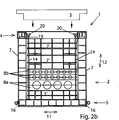
Der wannenförmige, oben offene Hauptkörper
Der Hauptkörper
Von unten nach oben besteht dieser Hauptkörper
Dabei können als Schrauben insbesondere Ösenschrauben verwendet werden, die anstelle eines normalen Schraubenkopfes eine Öse besitzen, so dass an diesen Ösen später ein Hebezeug eingehängt und der gesamte Hauptkörper
Auf die Oberseite der Bodenplatte
In den Eckbereichen stecken in dieser Bodenplatte
Zu diesem Zweck weisen die Pfosten, also Eckpfosten
Das Wesentliche des Hauptkörpers
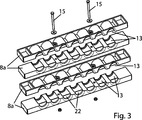
In den Kabeldurchgangsteilen
Durch Gegeneinanderlegen von zwei gleichen Kabeldurchgangsteilen z. B.
Da in jedem Anwendungsfall eines solchen Unterflurschachtes
Deshalb gibt es beispielsweise Kabeldurchgangsteile
Auf der Außenseite oder Innenseite oder in der Mitte, der Kabeldurchgangsteile, ist dabei die Kabeldurchgangsvertiefung
Das übereinander gelegte Paar oder mehrere übereinander gelegte Paare von Kabeldurchgangsteilen
Wenn auf diese Art und Weise die umlaufenden Wände des Hauptkörpers
Der Zuganker
Wie
Bei den Bodenplatten
Auf diese Art und Weise ist sichergestellt, dass diese Teile mit den geschlossenen glatten Seiten eine glatte, geschlossene Außenfläche des Hauptkörpers
In die nach oben offenen Schraubkanäle
Der obere Rahmen
Durch Aufschrauben der Spannmutter
Das Vorgehen bei der Herstellung des Hauptkörpers
Deshalb wird beim Einbau des Hauptkörpers
Bei mehreren Teil-Bodenplatten
Anschließend werden um die häufig auch nebeneinander mündenden Erdkabel, die sich auf gleicher Höhe befinden, von unten und oben her jeweils ein Kabeldurchgangsteil z. B.
Erst danach werden gegebenenfalls unterhalb der Kabeldurchgangsteile noch benötigte geschlossene Wandteile
Danach werden von oben her vertikal Eckpfosten
Dann werden die Wände des Hauptkörpers
Da auch die Kabeldurchgangsteile
Zusätzlich kann ein Bodenblech oder eine dünne Kunststoffplatte auf die nach oben offene Verrippung der Bodenplatte
Vor dem Aufsetzen des oberen Rahmens
Vorzugsweise wird diese Art der Versteifung auf den beiden Längsseiten des Rahmens
Die
Das niedrigere Wandteil
The lower wall part
Die Höhe der Kabeldurchgangsteile
In der Darstellung der langen Seite des Hauptkörpers
Das niedrige Wandteil
Dies zeigt die nach innen offene Verrippung und nach außen durchgehend geschlossene Fläche der Wandteile
Unter diesem Bereich mit Kabeldurchgangsteilen
Der Bereich der Kabeldurchgangsteile
Ferner besitzt die Bodenplatte einen erhöhten, umlaufenden Rand in der Höhe z. B. des Höhenrastermasses und der Breite eines Gefaches der Verrippung, um die Stabilität zu verbessern.Furthermore, the bottom plate has a raised, circumferential edge in the height z. As the height of the raster and the width of a trough of the ribbing to improve the stability.
BezugszeichenlisteLIST OF REFERENCE NUMBERS
- 11
- UnterflurschachtUnderfloor bay
- 22
- Hauptkörpermain body
- 33
- Deckelcover
- 44
- Rahmenframe
- 55
- Bodenplattebaseplate
- 5a, b5a, b
- Teil-BodenplattenPartial bottom plates
- 6a, b6a, b
- Pfostenpost
- 6'6 '
- Pfostenelementpost member
- 77
- Wandteilewall parts
- 8a, b8a, b
- KabeldurchgangsteileCable passage parts
- 99
- Kabeldurchlässecable outlets
- 1010
- Längsrichtung, LängserstreckungLongitudinal direction, longitudinal extent
- 1111
- Querrichtungtransversely
- 1212
- vertikale Richtungvertical direction
- 1313
- KabeldurchgangsvertiefungenCable passage grooves
- 1414
- Zugankertie rods
- 1515
- Spannschraubenturnbuckles
- 1616
- Flachmaterial aus StahlFlat material made of steel
- 16'16 '
- Flachmaterial aus MetallFlat material of metal
- 1717
- Schraubkanälescrew channels
- 1818
- Metalllaschemetal tab
- 1919
- horizontale Verstrebunghorizontal bracing
- 2020
- Spannmutterlocknut
- 2121
- Führungsvorsprüngeguide projections
- 2222
- Sollbruch-PlatteThe break-away plate
- 2323
- Versteifungsrohrstiffening tube
Claims (20)
Priority Applications (2)
| Application Number | Priority Date | Filing Date | Title |
|---|---|---|---|
| DE201010050964 DE102010050964B3 (en) | 2010-11-10 | 2010-11-10 | Underfloor bay |
| EP11188359.1A EP2453544A3 (en) | 2010-11-10 | 2011-11-09 | Underfloor shaft |
Applications Claiming Priority (1)
| Application Number | Priority Date | Filing Date | Title |
|---|---|---|---|
| DE201010050964 DE102010050964B3 (en) | 2010-11-10 | 2010-11-10 | Underfloor bay |
Publications (1)
| Publication Number | Publication Date |
|---|---|
| DE102010050964B3 true DE102010050964B3 (en) | 2012-02-16 |
Family
ID=45350405
Family Applications (1)
| Application Number | Title | Priority Date | Filing Date |
|---|---|---|---|
| DE201010050964 Expired - Fee Related DE102010050964B3 (en) | 2010-11-10 | 2010-11-10 | Underfloor bay |
Country Status (2)
| Country | Link |
|---|---|
| EP (1) | EP2453544A3 (en) |
| DE (1) | DE102010050964B3 (en) |
Cited By (7)
| Publication number | Priority date | Publication date | Assignee | Title |
|---|---|---|---|---|
| DE102012101366B3 (en) * | 2012-02-21 | 2013-04-18 | Berthold Sichert Gmbh | Under-floor shaft for arranging in under floor pit for protecting underground cables against e.g. ingress of soil, has wall strips and frames fixed against each other via sash fasteners, which lock and unlock rotation around specific degree |
| EP3605763A1 (en) * | 2018-07-30 | 2020-02-05 | Langmatz GmbH | Underfloor shaft, in particular for energy distribution and/or telecommunication |
| EP3919686A1 (en) * | 2020-06-03 | 2021-12-08 | Langmatz GmbH | Rectangular shaft |
| DE102020003345A1 (en) | 2020-06-03 | 2021-12-09 | Langmatz Gmbh | Manhole |
| CN114156785A (en) * | 2021-11-30 | 2022-03-08 | 南京苏秦电力设备安装有限公司 | Power cable laying process |
| DE102023112638A1 (en) | 2023-05-12 | 2024-11-14 | Belden Sichert GmbH | Earth shaft with a holder for distribution boxes and method for arranging an earth shaft in a footpath |
| DE102023112636A1 (en) | 2023-05-12 | 2024-11-14 | Belden Sichert GmbH | Device for limiting a cavity in the ground |
Families Citing this family (5)
| Publication number | Priority date | Publication date | Assignee | Title |
|---|---|---|---|---|
| CN111779032B (en) * | 2020-07-08 | 2025-08-19 | 国网江苏省电力有限公司连云港供电分公司 | Assembled combined octagonal cable well and construction method thereof |
| GB2618067A (en) * | 2022-04-19 | 2023-11-01 | Nal Ltd | Modular foundation chamber apparatus |
| AU2022303304A1 (en) * | 2021-06-28 | 2024-02-08 | Nal Limited | Modular electric vehicle charging foundation system |
| CN113833028B (en) * | 2021-10-15 | 2023-06-20 | 杭州金盟道路设施有限公司 | Spliced wiring wall body for underground operation |
| CN114665414B (en) * | 2022-01-26 | 2024-06-25 | 河南省资源环境调查三院有限公司 | Large-caliber drilling and cabling process |
Citations (4)
| Publication number | Priority date | Publication date | Assignee | Title |
|---|---|---|---|---|
| DE2549547A1 (en) * | 1975-11-05 | 1977-05-12 | Albert Stewing | Prefabricated cable shaft of reinforced concrete - has shaft trough split in longitudinal direction and both halves form seam |
| DE10314897B3 (en) * | 2003-04-01 | 2004-10-14 | Lic Langmatz Gmbh | Housing system for copper and/or glass fibre cable distributors has water-tight housing received in shaft embedded in ground |
| DE202007014465U1 (en) * | 2007-10-16 | 2007-12-20 | Frei Netzwerk Ausstattung Gmbh | Underfloor bay |
| DE102008012460B3 (en) * | 2008-03-04 | 2009-10-22 | Berthold Sichert Gmbh | Base plate with sealing blocks |
Family Cites Families (1)
| Publication number | Priority date | Publication date | Assignee | Title |
|---|---|---|---|---|
| DE9208786U1 (en) * | 1992-07-01 | 1992-09-10 | LIC Langmatz GmbH, 8100 Garmisch-Partenkirchen | Plastic cable duct |
-
2010
- 2010-11-10 DE DE201010050964 patent/DE102010050964B3/en not_active Expired - Fee Related
-
2011
- 2011-11-09 EP EP11188359.1A patent/EP2453544A3/en not_active Withdrawn
Patent Citations (4)
| Publication number | Priority date | Publication date | Assignee | Title |
|---|---|---|---|---|
| DE2549547A1 (en) * | 1975-11-05 | 1977-05-12 | Albert Stewing | Prefabricated cable shaft of reinforced concrete - has shaft trough split in longitudinal direction and both halves form seam |
| DE10314897B3 (en) * | 2003-04-01 | 2004-10-14 | Lic Langmatz Gmbh | Housing system for copper and/or glass fibre cable distributors has water-tight housing received in shaft embedded in ground |
| DE202007014465U1 (en) * | 2007-10-16 | 2007-12-20 | Frei Netzwerk Ausstattung Gmbh | Underfloor bay |
| DE102008012460B3 (en) * | 2008-03-04 | 2009-10-22 | Berthold Sichert Gmbh | Base plate with sealing blocks |
Cited By (10)
| Publication number | Priority date | Publication date | Assignee | Title |
|---|---|---|---|---|
| DE102012101366B3 (en) * | 2012-02-21 | 2013-04-18 | Berthold Sichert Gmbh | Under-floor shaft for arranging in under floor pit for protecting underground cables against e.g. ingress of soil, has wall strips and frames fixed against each other via sash fasteners, which lock and unlock rotation around specific degree |
| EP3605763A1 (en) * | 2018-07-30 | 2020-02-05 | Langmatz GmbH | Underfloor shaft, in particular for energy distribution and/or telecommunication |
| EP3919686A1 (en) * | 2020-06-03 | 2021-12-08 | Langmatz GmbH | Rectangular shaft |
| DE102020003345A1 (en) | 2020-06-03 | 2021-12-09 | Langmatz Gmbh | Manhole |
| DE102020003343A1 (en) | 2020-06-03 | 2021-12-30 | Langmatz Gmbh | Rectangular shaft |
| CN114156785A (en) * | 2021-11-30 | 2022-03-08 | 南京苏秦电力设备安装有限公司 | Power cable laying process |
| DE102023112638A1 (en) | 2023-05-12 | 2024-11-14 | Belden Sichert GmbH | Earth shaft with a holder for distribution boxes and method for arranging an earth shaft in a footpath |
| DE102023112636A1 (en) | 2023-05-12 | 2024-11-14 | Belden Sichert GmbH | Device for limiting a cavity in the ground |
| WO2024238488A1 (en) | 2023-05-12 | 2024-11-21 | Ppc Broadband, Inc. | Ground shaft including a side wall portion |
| WO2024238490A1 (en) | 2023-05-12 | 2024-11-21 | Ppc Broadband, Inc. | Street cabinet arrangement with underground base portion |
Also Published As
| Publication number | Publication date |
|---|---|
| EP2453544A3 (en) | 2014-07-02 |
| EP2453544A2 (en) | 2012-05-16 |
Similar Documents
| Publication | Publication Date | Title |
|---|---|---|
| DE102010050964B3 (en) | Underfloor bay | |
| DE112012004108T5 (en) | CONSTRUCTION BOX SYSTEM AND METHOD | |
| DE4206682C2 (en) | Housing, in particular cable junction boxes | |
| EP2921599B1 (en) | Element for the construction of a channel and method for laying elements | |
| DE102012101366B3 (en) | Under-floor shaft for arranging in under floor pit for protecting underground cables against e.g. ingress of soil, has wall strips and frames fixed against each other via sash fasteners, which lock and unlock rotation around specific degree | |
| EP2631370B1 (en) | Underfloor shaft | |
| DE69703959T2 (en) | CONTINUOUSLY REINFORCED PARTITION, RELATED PRODUCTION PROCESSES AND SHUTTERING | |
| DE102012217689A1 (en) | Wall formwork and wall formwork system | |
| DE202012002653U1 (en) | Prefabricated concrete component for creating sidewalls for silos and sidewall for a silo | |
| DE19739920A1 (en) | Method and shoring device for pipe installation | |
| DE19631275C1 (en) | Flood wall for building protection | |
| WO2008141620A2 (en) | Formwork devices and method for producing monolithic concrete structures | |
| DE202009003683U1 (en) | Apparatus for casting concrete wall elements | |
| DE19803074C2 (en) | Press shaft and method for creating one | |
| DE202017107261U1 (en) | Prefabricated concrete element with at least one load-bearing component | |
| CH713190A2 (en) | Device and method for connecting two components in a specific relative orientation and thus created concrete structure. | |
| DE202012100568U1 (en) | Underfloor bay | |
| DE2612048A1 (en) | PRE-FABRICATED ELEMENTS IN MODULAR DESIGN | |
| DE2336482A1 (en) | Prefabricated steel-skeleton room cell units - with frames of hollow sections covered by inner and outer insulating panels | |
| DE9407247U1 (en) | Trench stiffening element | |
| DE59504380C5 (en) | shoring | |
| EP2426264B1 (en) | Casing | |
| DE3115653C2 (en) | Energy distribution station | |
| DE19847672C1 (en) | One-piece drainage component for installation beneath edge area of road surface has load accommodation points, which define locating surface on one side of component | |
| DE4432306A1 (en) | Shuttering to support stepped walls of trench |
Legal Events
| Date | Code | Title | Description |
|---|---|---|---|
| R016 | Response to examination communication | ||
| R018 | Grant decision by examination section/examining division | ||
| R020 | Patent grant now final |
Effective date: 20120517 |
|
| R082 | Change of representative |
Representative=s name: WEICKMANN & WEICKMANN PATENTANWAELTE - RECHTSA, DE Representative=s name: PATENTANWAELTE WEICKMANN & WEICKMANN, DE |
|
| R119 | Application deemed withdrawn, or ip right lapsed, due to non-payment of renewal fee |