DE102010043723B4 - time-of-flight camera system - Google Patents
time-of-flight camera system Download PDFInfo
- Publication number
- DE102010043723B4 DE102010043723B4 DE102010043723.9A DE102010043723A DE102010043723B4 DE 102010043723 B4 DE102010043723 B4 DE 102010043723B4 DE 102010043723 A DE102010043723 A DE 102010043723A DE 102010043723 B4 DE102010043723 B4 DE 102010043723B4
- Authority
- DE
- Germany
- Prior art keywords
- time
- flight camera
- camera system
- reception
- photosensor
- Prior art date
- Legal status (The legal status is an assumption and is not a legal conclusion. Google has not performed a legal analysis and makes no representation as to the accuracy of the status listed.)
- Active
Links
Images


Classifications
-
- G—PHYSICS
- G01—MEASURING; TESTING
- G01S—RADIO DIRECTION-FINDING; RADIO NAVIGATION; DETERMINING DISTANCE OR VELOCITY BY USE OF RADIO WAVES; LOCATING OR PRESENCE-DETECTING BY USE OF THE REFLECTION OR RERADIATION OF RADIO WAVES; ANALOGOUS ARRANGEMENTS USING OTHER WAVES
- G01S7/00—Details of systems according to groups G01S13/00, G01S15/00, G01S17/00
- G01S7/48—Details of systems according to groups G01S13/00, G01S15/00, G01S17/00 of systems according to group G01S17/00
- G01S7/481—Constructional features, e.g. arrangements of optical elements
- G01S7/4814—Constructional features, e.g. arrangements of optical elements of transmitters alone
-
- G—PHYSICS
- G01—MEASURING; TESTING
- G01S—RADIO DIRECTION-FINDING; RADIO NAVIGATION; DETERMINING DISTANCE OR VELOCITY BY USE OF RADIO WAVES; LOCATING OR PRESENCE-DETECTING BY USE OF THE REFLECTION OR RERADIATION OF RADIO WAVES; ANALOGOUS ARRANGEMENTS USING OTHER WAVES
- G01S17/00—Systems using the reflection or reradiation of electromagnetic waves other than radio waves, e.g. lidar systems
- G01S17/88—Lidar systems specially adapted for specific applications
- G01S17/89—Lidar systems specially adapted for specific applications for mapping or imaging
- G01S17/894—Three-dimensional [3D] imaging with simultaneous measurement of time-of-flight at a two-dimensional [2D] array of receiver pixels, e.g. time-of-flight cameras or flash lidar
-
- G—PHYSICS
- G01—MEASURING; TESTING
- G01S—RADIO DIRECTION-FINDING; RADIO NAVIGATION; DETERMINING DISTANCE OR VELOCITY BY USE OF RADIO WAVES; LOCATING OR PRESENCE-DETECTING BY USE OF THE REFLECTION OR RERADIATION OF RADIO WAVES; ANALOGOUS ARRANGEMENTS USING OTHER WAVES
- G01S7/00—Details of systems according to groups G01S13/00, G01S15/00, G01S17/00
- G01S7/48—Details of systems according to groups G01S13/00, G01S15/00, G01S17/00 of systems according to group G01S17/00
- G01S7/481—Constructional features, e.g. arrangements of optical elements
- G01S7/4814—Constructional features, e.g. arrangements of optical elements of transmitters alone
- G01S7/4815—Constructional features, e.g. arrangements of optical elements of transmitters alone using multiple transmitters
-
- G—PHYSICS
- G01—MEASURING; TESTING
- G01S—RADIO DIRECTION-FINDING; RADIO NAVIGATION; DETERMINING DISTANCE OR VELOCITY BY USE OF RADIO WAVES; LOCATING OR PRESENCE-DETECTING BY USE OF THE REFLECTION OR RERADIATION OF RADIO WAVES; ANALOGOUS ARRANGEMENTS USING OTHER WAVES
- G01S17/00—Systems using the reflection or reradiation of electromagnetic waves other than radio waves, e.g. lidar systems
- G01S17/02—Systems using the reflection of electromagnetic waves other than radio waves
- G01S17/06—Systems determining position data of a target
- G01S17/08—Systems determining position data of a target for measuring distance only
- G01S17/32—Systems determining position data of a target for measuring distance only using transmission of continuous waves, whether amplitude-, frequency-, or phase-modulated, or unmodulated
- G01S17/36—Systems determining position data of a target for measuring distance only using transmission of continuous waves, whether amplitude-, frequency-, or phase-modulated, or unmodulated with phase comparison between the received signal and the contemporaneously transmitted signal
Landscapes
- Engineering & Computer Science (AREA)
- Physics & Mathematics (AREA)
- Computer Networks & Wireless Communication (AREA)
- General Physics & Mathematics (AREA)
- Radar, Positioning & Navigation (AREA)
- Remote Sensing (AREA)
- Electromagnetism (AREA)
- Optical Radar Systems And Details Thereof (AREA)
Abstract
Lichtlaufzeitkamerasystem (1),mit einer Lichtlaufzeit-Kamera (20) zur Erfassung eines Empfangsbereichs (EB), die einen Photosensor (22), mit mehreren, Empfangspixeln und eine Empfangsoptik (25) aufweist,mit mehreren Beleuchtungsmodulen (10) zur Beleuchtung eines Sendebereichs (SB), das eine Beleuchtungslichtquelle (12) und eine Strahlformungsoptik (15) aufweist, und mit einem Modulator (30) zur Bereitstellung einer Modulationsfrequenz, der mit dem Photosensor (22) und den Beleuchtungslichtquellen (12) verbunden ist,dadurch gekennzeichnet,dass das Lichtlaufzeitkamerasystem (1) gegenüber einem Überwachungsbereich (SB, EB) gekippt ausgerichtet ist,dass eine Lichtstärke (IS) von mehreren Beleuchtungsmodulen (10) emittierten Strahlung derart vorgegeben ist,dass ein Lichtstrom (ϕi) für alle Empfangspixel des Photosensor (22) innerhalb tolerierter Grenzen im Wesentlichen konstant ist.Time-of-flight camera system (1), with a time-of-flight camera (20) for capturing a reception area (EB), which has a photo sensor (22) with a plurality of reception pixels and reception optics (25), with a plurality of lighting modules (10) for illuminating a transmission area (SB) having an illumination light source (12) and beam shaping optics (15), and having a modulator (30) for providing a modulation frequency, which is connected to the photosensor (22) and the illumination light sources (12), characterized in that the time-of-flight camera system (1) is aligned tilted in relation to a surveillance area (SB, EB), that a light intensity (IS) of radiation emitted by a number of lighting modules (10) is specified in such a way that a luminous flux (ϕi) for all reception pixels of the photosensor (22) within tolerated limits is essentially constant.
Description
Die Erfindung betrifft ein Lichtlaufzeitkamerasystem und ein Verfahren zum Betreiben eines solchen Systems nach Gattung der unabhängigen Ansprüche.The invention relates to a time-of-flight camera system and a method for operating such a system according to the species of the independent claims.
Mit Lichtlaufzeit-Kamerasystem sollen nicht nur Systeme umfasst sein, die Entfernungen direkt aus der Lichtlaufzeit ermitteln, sondern insbesondere auch alle Lichtlaufzeit bzw. 3D-TOF-Kamerasysteme, die eine Laufzeitinformation aus der Phasenverschiebung einer emittierten und empfangenen Strahlung gewinnen. Als Lichtlaufzeit bzw. 3D-TOF-Kameras sind insbesondere PMD-Kameras mit Photomischdetektoren (PMD) geeignet, wie sie u.a. in den Anmeldungen
Aus der
Die
Aufgabe der Erfindung ist es, die Vorrichtung im Hinblick einer Funktionssicherheit weiter zu gestalten.The object of the invention is to further develop the device with regard to functional reliability.
Die Aufgabe wird in vorteilhafter Weise durch das erfindungsgemäße Lichtlaufzeitkamerasystem und das Verfahren zum Betreiben eines solchen Systems entsprechend der unabhängigen Ansprüche gelöst.The object is advantageously achieved by the time-of-flight camera system according to the invention and the method for operating such a system according to the independent claims.
Vorgesehen ist ein Lichtlaufzeitkamerasystem, mit einer Lichtlaufzeitkamera zur Erfassung eines Empfangsbereichs, mit mehreren Beleuchtungsmodulen zur Beleuchtung eines Sendebereichs und einem Modulator zur Bereitstellung einer Modulationsfrequenz. Die Lichtlaufzeitkamera weist eine Empfangsoptik und einen Photosensor auf, der insbesondere als Photomischdetektor mit mehreren Empfangspixeln ausgebildet ist. Die Beleuchtungslichtquelle ist im Weiteren mit einer Strahlformungsoptik zur Beeinflussung der Beleuchtung auf. Ferner sind der Photosensor und die Beleuchtungslichtquelle mit dem Modulator verbunden.A time-of-flight camera system is provided, with a time-of-flight camera for detecting a reception area, with a plurality of lighting modules for illuminating a transmission area and a modulator for providing a modulation frequency. The time-of-flight camera has receiving optics and a photosensor, which is designed in particular as a photomixing detector with a plurality of receiving pixels. The illumination light source is also equipped with beam-shaping optics for influencing the illumination. Furthermore, the photosensor and the illumination light source are connected to the modulator.
Vorteilhaft ist es vorgesehen, eine Sendelichtstärke einer von den Beleuchtungsmodulen emittierten Strahlung derart vorzugeben, dass ein aus dem Empfangsbereich vom Photosensor empfangener Lichtstrom für alle Empfangspixel innerhalb tolerierter Grenzen im Wesentlichen konstant ist.Provision is advantageously made to specify a transmitted light intensity of a radiation emitted by the lighting modules in such a way that a luminous flux received from the receiving area by the photosensor is essentially constant for all receiving pixels within tolerable limits.
Dieses Vorgehen hat den Vorteil, dass in Reaktion auf bestimmte Einbausituationen der Lichtlaufzeitkamera die Beleuchtungen so angepasst werden können, dass am Photosensor vorzugsweise für alle Empfangspixel eine innerhalb gewisser Grenzen im Wesentlichen konstante Empfangsintensität vorliegt. Dies hat insbesondere den Vorteil, dass im Wesentlichen für alle Empfangspixel ein vergleichbarer Signal-Rauschabstand vorliegt und die Messergebnisse eine höhere Zuverlässigkeit aufweisen. Darüber hinaus vereinfacht sich aufgrund der geringeren Dynamik auf Empfangsseite auch die Signalverarbeitung und ferner wird durch dieses Vorgehen eine geringere Lichtleistung benötigt.This procedure has the advantage that, in response to certain installation situations of the time-of-flight camera, the lighting can be adjusted in such a way that the reception intensity is essentially constant within certain limits for all reception pixels at the photosensor. This has the particular advantage that there is a comparable signal-to-noise ratio for essentially all receiving pixels and the measurement results are more reliable. In addition, due to the lower dynamics on the receiving side, the signal processing is also simplified and this procedure also requires a lower light output.
Vorteilhaft wird die Sendeintensität beispielsweise durch Anpassung der Strahlformungsoptik vorgegeben und /oder durch einen Einsatz mehrerer Beleuchtungsmodule und/oder durch eine Zusammenfassung mehrerer Beleuchtungslichtquellen.The transmission intensity is advantageously specified, for example, by adapting the beam-shaping optics and/or by using a plurality of illumination modules and/or by combining a plurality of illumination light sources.
Nachfolgend wird die Erfindung anhand von Ausführungsbeispielen unter Bezugnahme auf die Zeichnungen näher erläutert.The invention is explained in more detail below using exemplary embodiments with reference to the drawings.
Es zeigen schematisch:
-
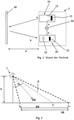
1 das Grundprinzip einer Lichtlaufzeitkamera nach dem PMD-Prinzip, -
2 ein erfindungsgemäßes Lichtlaufzeitkamerasystem.
-
1 the basic principle of a time-of-flight camera based on the PMD principle, -
2 a time-of-flight camera system according to the invention.
Bei der nachfolgenden Beschreibung der bevorzugten Ausführungsformen bezeichnen gleiche Bezugszeichen gleiche oder vergleichbare Komponenten.In the following description of the preferred embodiments, the same reference symbols designate the same or comparable components.
Das Lichtlaufzeit-Kamerasystem 1 umfasst eine Sendeeinheit bzw. ein Beleuchtungsmodul 10 mit einer Beleuchtungslichtquelle 12 und einer dazugehörigen Strahlformungsoptik 15 sowie eine Empfangseinheit bzw. Lichtlaufzeit-Kamera 20 mit einer Empfangsoptik 25 und einem Photosensor 22. Der Photosensor 22 weist mindestens ein Pixel, vorzugsweise jedoch ein Pixel-Array, auf und ist insbesondere als Photomischdetektor ausgebildet. Die Empfangsoptik 25 besteht typischerweise zur Verbesserung der Abbildungseigenschaften aus mehreren optischen Elementen. Die Strahlformungsoptik 15 der Sendeeinheit 10 ist vorzugsweise als Reflektor ausgebildet. Es können jedoch auch diffraktive Elemente oder Kombinationen aus reflektierenden und diffraktiven Elementen eingesetzt werden.The time-of-
Das Messprinzip dieser Anordnung basiert im Wesentlichen darauf, dass ausgehend von der Phasenverschiebung des emittierten und empfangenen Lichts die Laufzeit des emittierten und reflektierten Lichts ermittelt werden kann. Zu diesem Zwecke werden die Lichtquelle 12 und der Photosensor 22 über einen Modulator 30 gemeinsam mit einer bestimmten Modulationsfrequenz mit einer ersten Phasenlage a beaufschlagt. Entsprechend der Modulationsfrequenz sendet die Lichtquelle 12 ein amplitudenmoduliertes Signal mit der Phaselage a aus. Dieses Signal bzw. die elektromagnetische Strahlung wird im dargestellten Fall von einem Objekt 40 reflektiert und trifft aufgrund der zurückgelegten Wegstrecke entsprechend phasenverschoben mit einer zweiten Phasenlage b auf den Photosensor 22. Im Photosensor 22 wird das Signal der ersten Phasenlage a des Modulators 30 mit dem empfangenen Signal, das die laufzeitbedingte zweiten Phasenlage b aufweist, gemischt, wobei aus dem resultierenden Signal die Phasenverschiebung bzw. die Objektentfernung d ermittelt wird.The measuring principle of this arrangement is essentially based on the fact that the propagation time of the emitted and reflected light can be determined based on the phase shift of the emitted and received light. For this purpose, the
In
Der Einfachheit sei hier angenommen, dass der Sendebereich SB der Beleuchtung 10 im Wesentlichen mit dem Empfangsbereich EB der Lichtlaufzeitkamera 20 übereinstimmt.For the sake of simplicity, it is assumed here that the transmission range SB of the
Typischerweise ist für die Überwachung von Türen und Toren, Sicherheitszellen, Gängen etc. die Lichtlaufzeitkamera 20 bzw. das Lichtlaufzeitkamerasystem 1 ortfest installiert, so dass keine dynamischen Änderungen der Kameraposition zu berücksichtigen sind.The time-of-
Die Distanzen der Objekte und des Hintergrundes in dem Empfangsbereich EB werden wie unter
Zu Vermeidung dieser Nachteile ist es erfindungsgemäß vorgesehen, die Lichtstärke der Beleuchtung an den Sichtbereich bzw. Empfangsbereich EB der Lichtlaufzeitkamera 10 anzupassen.In order to avoid these disadvantages, it is provided according to the invention to adapt the light intensity of the illumination to the field of view or reception area EB of the time-of-
Aufgrund der gegenüber dem Überwachungs- bzw. Sende- und Empfangsbereich SB, EB gekippten Ausrichtung der Lichtlaufzeitkamera 20 bzw. des Lichtlaufzeitkamerasystems 1 gibt es Bereiche, die relativ nah und entsprechend weiter von der Kamera entfernt sind. Womit das erfasste Nutzsignal und der erzielbare Signal-Rauschabstand bei einer zur Kamerablickrichtung BR symmetrischen Ausleuchtung immer vom Detektionsort abhängen werden. Darüber hinaus ist aufgrund der über den Sende- bzw. Empfangsbereich SB, EB variierende Intensität des Nutzsignals auch keine konstante Genauigkeit der Entfernungsmessung gewährleistet.Because the orientation of the time-of-
Die erfindungsgemäße Optimierung der Beleuchtung für einen stationären Einsatz des Lichtlaufzeitkamerasystems 1 hebt im Wesentlich auf eine detaillierte Analyse der Einbausituation des Lichtlaufzeitkamerasystems 1 ab. Zu berücksichtigen sind vornehmlich die Einbauhöhe h, der Blickwinkel, die Umgebung, die Spezifikation der Objekte und welche Genauigkeit der Messung gewünscht ist. Gegebenenfalls können auch eine Helligkeitsübertragungsfunktion des eingesetzten Objektivs 25 berücksichtigt werden.The optimization of the lighting according to the invention for stationary use of the time-of-
Nach Analyse der Einbau- bzw. Einsatzsituation kann für jeden Ort des Überwachungsbereichs bzw. des Sichtbereichs SB der Lichtlaufzeitkamera 22 beispielsweise eine Mindestlichtleistung/-menge, -intensität oder ein Mindestlichtstrom bestimmt werden. After analyzing the installation or use situation, a minimum light output/amount, intensity or a minimum luminous flux can be determined for each location of the monitored area or the viewing area SB of the time-of-
Der vom Photosensor 22 erfasste Lichtstrom ϕE hängt im Wesentlichen von der Beleuchtungsstärke E im erfassten Bereichs EB ab, die wiederum in bekannter Weise proportional zur Lichtstärke Is der Lichtquelle 22 und umgekehrt proportional zum Quadrat des Abstandes d ist, also:
Dies gilt für alle Blickwinkel αi, auch für die auf der Bilddiagonalen, die hier nicht gezeigt sind. Eine entsprechende Intensitätsverteilung lässt sich vorzugsweise durch Anpassung der Strahlformungsoptik 15 beispielsweise durch Vorsatzlinsen, diffraktive optische Elemente, Spiegelflächen, Totalreflexionsflächen etc. erreichen.This applies to all viewing angles αi, including those on the image diagonal that are not shown here. A corresponding intensity distribution can preferably be achieved by adapting the beam-
Die obige Rechnung geht von einem Objektiv mit über den Objektwinkel konstanter Helligkeit aus. Dies ist in der Realität meistens nicht der Fall, und kann beim Design der Beleuchtungsoptik mit berücksichtigt werden.The above calculation is based on a lens with constant brightness over the object angle. In reality, this is usually not the case and can be taken into account when designing the lighting optics.
Ist die relative Helligkeit des Objektivs bzw. das winkelabhängige Transmissionsverhalten fObj(αi) bekannt, so gilt für den am Sensor erforderlichen Lichtstrom ϕs(αi):
Selbstverständlich können hierbei noch weitere beeinflussende Faktoren berücksichtigt werden, wie beispielsweise das Reflektionsverhalten der Objekte im Erfassungsbereich.Of course, other influencing factors can also be taken into account here, such as the reflection behavior of the objects in the detection area.
Dem ersten Diagramm ist zu entnehmen, dass eine unkompensierte Beleuchtung in allen Raumrichtungen αi im Wesentlichen mit einer konstanten Intensität Strahlung emittiert.The first diagram shows that uncompensated illumination emits radiation in all spatial directions α i essentially with a constant intensity.
Der Lichtstrom ϕE am Photosensor 22 bzw. die Beleuchtungsstärke E im Empfangsbereich EB hängt jedoch wie zuvor beschrieben insbesondere von der Einbausituation des Lichtlaufzeitkamerasystems 1 sowie unter anderem auch von den Eigenschaften des Objektivs 25 der Lichtlaufzeitkamera 20.The luminous flux ϕ E at the
Das zweite Diagramm der


Wie im ersten Diagramm der
Im Ergebnis weist dann der Lichtstrom ϕE(αi) am Photosensor 22 über den Empfangsbereich EB einen im Wesentlichen konstanten Verlauf auf.As a result, the luminous flux φ E (α i ) at the
Wie bereits eingangs beschrieben, hat dieses Vorgehen den Vorteil, dass das elektrische Verhalten des Photosensors über die gesamte Sensorfläche im Wesentlichen konstant ist und die elektrische Auswertung wesentlich vereinfacht und zuverlässiger macht.As already described at the outset, this procedure has the advantage that the electrical behavior of the photosensor is essentially constant over the entire sensor surface and makes the electrical evaluation significantly easier and more reliable.
Darüber hinaus bietet ein solches Vorgehen insbesondere auch für sicherheitskritische Anwendungen Vorteile. Ist das Beleuchtungssystem erfindungsgemäß kompensiert, so erhält jeder Photosensor einen im Wesentlichen gleichen Lichtstrom, so dass auch das Amplitudenbild des Photosensors im Wesentlichen für alle Empfangspixel die gleiche Helligkeit aufweist. Dringt nun ein Objekt in den Erfassungsbereich ein, so ist das Objekt leicht aufgrund seiner vom Hintergrund abweichenden Helligkeit zu unterscheiden. Gegebenfalls können dann die weiteren Entfernungsmessungen auf das eindringende Objekt beschränkt werden.In addition, such a procedure offers advantages in particular for safety-critical applications. If the illumination system is compensated according to the invention, each photo sensor receives essentially the same luminous flux, so that the amplitude image of the photo sensor also has essentially the same brightness for all receiving pixels. If an object enters the detection area, the object can be easily distinguished due to its brightness, which differs from the background. If necessary, the further distance measurements can then be limited to the penetrating object.
Eine Einstellung des Lichtstroms am Photosensor kann beispielsweise durch eine geeignete Gestaltung der Strahlformungsoptik 15 der Beleuchtung 10 durchgeführt werden. Erfindungsgemäß ist es vorgesehen, ein System mit mehreren Beleuchtungen 10 bzw. Beleuchtungsmodulen vorzusehen, wobei die Beleuchtungsmodule so ausgerichtet werden, dass für den jeweiligen Anwendungsfall das Beleuchtungsprofil bzw. die winkelabhängige Lichtstärke erfindungsgemäß angepasst ist.The luminous flux at the photosensor can be adjusted, for example, by suitably designing the beam-shaping
Eine weitere Ausgestaltung geht von einem Beleuchtungsarray aus, bei dem jede einzelne Beleuchtung 10 eine Lichtquelle 12 und ein Strahlformungsoptik 15 aufweist oder bei der ggf. auch mehrere Lichtquellen 12 einer Strahlformungsoptik 15 zugeordnet sind. Die winkelabhängige Lichtstärke kann dann zusätzlich oder alternativ durch eine unterschiedliche elektrische Ansteuerung der Belichtungsquellen selbst eingestellt werden. A further configuration is based on an illumination array in which each
BezugszeichenlisteReference List
- 1010
- Sendeeinheittransmitter unit
- 1212
- Beleuchtungslichtquelleillumination light source
- 1515
- Strahlformungsoptikbeam shaping optics
- 2020
- Empfangseinheitreceiving unit
- 2222
- Photosensorphotosensor
- 2525
- Empfangsoptik für NutzlichtReceiving optics for useful light
- 3030
- Modulator, ModulationsgeneratorModulator, modulation generator
- 4040
- Objektobject
Claims (4)
Priority Applications (1)
| Application Number | Priority Date | Filing Date | Title |
|---|---|---|---|
| DE102010043723.9A DE102010043723B4 (en) | 2010-11-10 | 2010-11-10 | time-of-flight camera system |
Applications Claiming Priority (1)
| Application Number | Priority Date | Filing Date | Title |
|---|---|---|---|
| DE102010043723.9A DE102010043723B4 (en) | 2010-11-10 | 2010-11-10 | time-of-flight camera system |
Publications (2)
| Publication Number | Publication Date |
|---|---|
| DE102010043723A1 DE102010043723A1 (en) | 2012-05-10 |
| DE102010043723B4 true DE102010043723B4 (en) | 2022-03-10 |
Family
ID=45970970
Family Applications (1)
| Application Number | Title | Priority Date | Filing Date |
|---|---|---|---|
| DE102010043723.9A Active DE102010043723B4 (en) | 2010-11-10 | 2010-11-10 | time-of-flight camera system |
Country Status (1)
| Country | Link |
|---|---|
| DE (1) | DE102010043723B4 (en) |
Families Citing this family (6)
| Publication number | Priority date | Publication date | Assignee | Title |
|---|---|---|---|---|
| DE102013007743A1 (en) | 2012-05-08 | 2013-11-14 | Vision Tools Bildanalyse Systeme Gmbh | Method for unloading objects with sensor system, involves generating depth picture in pose and another pose, where poses are calculated from rough calculation of position of one or more objects |
| DE102012208995B4 (en) * | 2012-05-29 | 2017-12-07 | pmdtechnologies ag | Time of flight camera system with data channel |
| DE102014009143B4 (en) | 2014-06-20 | 2018-04-05 | Audi Ag | Motor vehicle camera device with controllable active illumination, motor vehicle with a camera device and method for generating camera images |
| DE102015115101A1 (en) * | 2015-09-08 | 2017-03-09 | Huf Hülsbeck & Fürst Gmbh & Co. Kg | Sensor system of a sensor device of a motor vehicle |
| DE102016202181A1 (en) * | 2016-02-12 | 2017-08-17 | pmdtechnologies ag | Lighting for a 3D camera |
| CN114556136A (en) * | 2019-10-24 | 2022-05-27 | 索尼半导体解决方案公司 | Illumination device, light detection device and method |
Citations (5)
| Publication number | Priority date | Publication date | Assignee | Title |
|---|---|---|---|---|
| US3815994A (en) | 1972-03-31 | 1974-06-11 | Kaman Sciences Corp | System and method for measuring distance |
| DE19704496A1 (en) | 1996-09-05 | 1998-03-12 | Rudolf Prof Dr Ing Schwarte | Method and device for determining the phase and / or amplitude information of an electromagnetic wave |
| DE19914962A1 (en) | 1999-04-01 | 2000-10-26 | Leuze Electronic Gmbh & Co | Optoelectronic device |
| US6587186B2 (en) | 2000-06-06 | 2003-07-01 | Canesta, Inc. | CMOS-compatible three-dimensional image sensing using reduced peak energy |
| EP1777747A1 (en) | 2005-10-19 | 2007-04-25 | CSEM Centre Suisse d'Electronique et de Microtechnique SA | Device and method for the demodulation of modulated electromagnetic wave fields |
-
2010
- 2010-11-10 DE DE102010043723.9A patent/DE102010043723B4/en active Active
Patent Citations (5)
| Publication number | Priority date | Publication date | Assignee | Title |
|---|---|---|---|---|
| US3815994A (en) | 1972-03-31 | 1974-06-11 | Kaman Sciences Corp | System and method for measuring distance |
| DE19704496A1 (en) | 1996-09-05 | 1998-03-12 | Rudolf Prof Dr Ing Schwarte | Method and device for determining the phase and / or amplitude information of an electromagnetic wave |
| DE19914962A1 (en) | 1999-04-01 | 2000-10-26 | Leuze Electronic Gmbh & Co | Optoelectronic device |
| US6587186B2 (en) | 2000-06-06 | 2003-07-01 | Canesta, Inc. | CMOS-compatible three-dimensional image sensing using reduced peak energy |
| EP1777747A1 (en) | 2005-10-19 | 2007-04-25 | CSEM Centre Suisse d'Electronique et de Microtechnique SA | Device and method for the demodulation of modulated electromagnetic wave fields |
Also Published As
| Publication number | Publication date |
|---|---|
| DE102010043723A1 (en) | 2012-05-10 |
Similar Documents
| Publication | Publication Date | Title |
|---|---|---|
| DE102015205826B4 (en) | Distance measuring system with time-of-flight pixel line | |
| DE102010043723B4 (en) | time-of-flight camera system | |
| DE102013207649B4 (en) | Time of flight camera system | |
| DE102016204140B3 (en) | Apparatus and method for calibrating a light runtime camera | |
| DE102009029364A1 (en) | Measuring device for measuring a distance between the measuring device and a target object by means of optical measuring radiation | |
| DE102009045323A1 (en) | Optical distance measuring device with calibration device | |
| DE10222797C5 (en) | distance determination | |
| EP3029494A1 (en) | Optoelectronic sensor | |
| DE10217294A1 (en) | sensor orientation | |
| DE102019005060A1 (en) | Distance measuring device that detects an optical system abnormality | |
| DE102009046108B4 (en) | camera system | |
| DE102016221184B4 (en) | Calibration device and calibration procedure for a camera system | |
| DE102013203088A1 (en) | Light running time camera system has lighting elements which are operated with different phases, and integration time varies in length for various phase positions, while integration time lasts longer than modulation time of illumination | |
| EP1211480A2 (en) | Electro-optical measuring device to determine the relative position of workpieces or their surfaces | |
| DE102016219518B4 (en) | Time of flight camera system | |
| DE602004003912T2 (en) | Device and method for measuring the visibility | |
| DE102006013340A1 (en) | Apparatus and method for detecting optical systems in a terrain area | |
| DE102013007859B3 (en) | Time-of-flight system with spatially separated transmitters and distance measurement method of an object | |
| DE4422886C2 (en) | Method and device for the optical determination of spatial positions of individual reflecting objects | |
| DE102016219516B4 (en) | Time of flight camera system | |
| DE102020208104A1 (en) | LiDAR sensor, especially vertical flash LiDAR sensor | |
| DE102016202181A1 (en) | Lighting for a 3D camera | |
| DE102016219510A1 (en) | Time of flight camera system | |
| DE102009045553B4 (en) | Time of flight measurement system | |
| DE102019124141A1 (en) | Time-of-flight camera system |
Legal Events
| Date | Code | Title | Description |
|---|---|---|---|
| R081 | Change of applicant/patentee |
Owner name: PMDTECHNOLOGIES AG, DE Free format text: FORMER OWNER: IFM ELECTRONIC GMBH, 45128 ESSEN, DE |
|
| R012 | Request for examination validly filed | ||
| R081 | Change of applicant/patentee |
Owner name: PMDTECHNOLOGIES AG, DE Free format text: FORMER OWNER: PMDTECHNOLOGIES AG, 57076 SIEGEN, DE |
|
| R082 | Change of representative |
Representative=s name: SCHUHMANN, JOERG, DIPL.-PHYS. DR. RER. NAT., DE |
|
| R016 | Response to examination communication | ||
| R018 | Grant decision by examination section/examining division | ||
| R020 | Patent grant now final |