DE102010028764A1 - Heel unit for a binding, in particular touring ski binding - Google Patents
Heel unit for a binding, in particular touring ski binding Download PDFInfo
- Publication number
- DE102010028764A1 DE102010028764A1 DE102010028764A DE102010028764A DE102010028764A1 DE 102010028764 A1 DE102010028764 A1 DE 102010028764A1 DE 102010028764 A DE102010028764 A DE 102010028764A DE 102010028764 A DE102010028764 A DE 102010028764A DE 102010028764 A1 DE102010028764 A1 DE 102010028764A1
- Authority
- DE
- Germany
- Prior art keywords
- heel
- main body
- heel unit
- control
- normal position
- Prior art date
- Legal status (The legal status is an assumption and is not a legal conclusion. Google has not performed a legal analysis and makes no representation as to the accuracy of the status listed.)
- Ceased
Links
- 230000027455 binding Effects 0.000 title claims abstract description 12
- 238000009739 binding Methods 0.000 title claims abstract description 12
- 230000033001 locomotion Effects 0.000 claims description 40
- 230000005540 biological transmission Effects 0.000 claims description 35
- 230000007246 mechanism Effects 0.000 description 18
- 230000008859 change Effects 0.000 description 3
- 230000009194 climbing Effects 0.000 description 3
- 238000010276 construction Methods 0.000 description 2
- 238000003754 machining Methods 0.000 description 2
- 238000004519 manufacturing process Methods 0.000 description 2
- 238000007493 shaping process Methods 0.000 description 2
- 230000007480 spreading Effects 0.000 description 2
- 238000003892 spreading Methods 0.000 description 2
- BUHVIAUBTBOHAG-FOYDDCNASA-N (2r,3r,4s,5r)-2-[6-[[2-(3,5-dimethoxyphenyl)-2-(2-methylphenyl)ethyl]amino]purin-9-yl]-5-(hydroxymethyl)oxolane-3,4-diol Chemical compound COC1=CC(OC)=CC(C(CNC=2C=3N=CN(C=3N=CN=2)[C@H]2[C@@H]([C@H](O)[C@@H](CO)O2)O)C=2C(=CC=CC=2)C)=C1 BUHVIAUBTBOHAG-FOYDDCNASA-N 0.000 description 1
- 230000002411 adverse Effects 0.000 description 1
- 230000000712 assembly Effects 0.000 description 1
- 238000000429 assembly Methods 0.000 description 1
- 230000008901 benefit Effects 0.000 description 1
- 230000008878 coupling Effects 0.000 description 1
- 238000010168 coupling process Methods 0.000 description 1
- 238000005859 coupling reaction Methods 0.000 description 1
- 238000006073 displacement reaction Methods 0.000 description 1
- 230000009977 dual effect Effects 0.000 description 1
- 210000003746 feather Anatomy 0.000 description 1
- 238000012423 maintenance Methods 0.000 description 1
- 239000002184 metal Substances 0.000 description 1
- 230000002093 peripheral effect Effects 0.000 description 1
Images


Classifications
-
- A—HUMAN NECESSITIES
- A63—SPORTS; GAMES; AMUSEMENTS
- A63C—SKATES; SKIS; ROLLER SKATES; DESIGN OR LAYOUT OF COURTS, RINKS OR THE LIKE
- A63C9/00—Ski bindings
- A63C9/08—Ski bindings yieldable or self-releasing in the event of an accident, i.e. safety bindings
- A63C9/0807—Ski bindings yieldable or self-releasing in the event of an accident, i.e. safety bindings for both towing and downhill skiing
-
- A—HUMAN NECESSITIES
- A63—SPORTS; GAMES; AMUSEMENTS
- A63C—SKATES; SKIS; ROLLER SKATES; DESIGN OR LAYOUT OF COURTS, RINKS OR THE LIKE
- A63C9/00—Ski bindings
- A63C9/08—Ski bindings yieldable or self-releasing in the event of an accident, i.e. safety bindings
- A63C9/082—Ski bindings yieldable or self-releasing in the event of an accident, i.e. safety bindings with swivel heel-plate
-
- A—HUMAN NECESSITIES
- A63—SPORTS; GAMES; AMUSEMENTS
- A63C—SKATES; SKIS; ROLLER SKATES; DESIGN OR LAYOUT OF COURTS, RINKS OR THE LIKE
- A63C9/00—Ski bindings
- A63C9/08—Ski bindings yieldable or self-releasing in the event of an accident, i.e. safety bindings
- A63C9/084—Ski bindings yieldable or self-releasing in the event of an accident, i.e. safety bindings with heel hold-downs, e.g. swingable
- A63C9/0845—Ski bindings yieldable or self-releasing in the event of an accident, i.e. safety bindings with heel hold-downs, e.g. swingable the body or base or a jaw pivoting about a vertical axis, i.e. side release
-
- A—HUMAN NECESSITIES
- A63—SPORTS; GAMES; AMUSEMENTS
- A63C—SKATES; SKIS; ROLLER SKATES; DESIGN OR LAYOUT OF COURTS, RINKS OR THE LIKE
- A63C9/00—Ski bindings
- A63C9/08—Ski bindings yieldable or self-releasing in the event of an accident, i.e. safety bindings
- A63C9/086—Ski bindings yieldable or self-releasing in the event of an accident, i.e. safety bindings using parts which are fixed on the shoe of the user and are releasable from the ski binding
Landscapes
- Footwear And Its Accessory, Manufacturing Method And Apparatuses (AREA)
Abstract
Die vorliegende Erfindung stellt eine Ferseneinheit (10) für eine Bindung bereit, welche umfasst: einen am Ski zu befestigenden Basiskörper (18), der eine Vorwärtsrichtung (X) definiert, einen zwischen einer Normalstellung und einer Seitenauslösestellung verschwenkbar am Basiskörper (18) montierten Hauptkörper (22), zwei nebeneinander angeordnete Ferseneingriffsvorsprünge (26a, 26b) für den Eingriff in Ausnehmungen eines Fersenabschnitts eines Schuhs, um den Schuh an der Ferseneinheit (10) zu fixieren, wobei die Ferseneingriffsvorsprünge (26a, 26b) in der Normalstellung des Hauptkörpers (22) im Wesentlichen in Vorwärtsrichtung (X) von dem Hauptkörper (22) vorstehen, eine erste Spannvorrichtung (44a, 44b, 32, 38), welche die Ferseneingriffsvorsprünge (26a, 26b) zueinander hin vorspannt, eine zweite Spannvorrichtung (44a, 44b, 32, 60), welche den Hauptkörper (22) zu der Normalstellung hin vorspannt, wobei ein elastisches Element (44a, 44b) vorgesehen ist, welches sowohl Spannkraft für die erste Spannvorrichtung als auch Spannkraft für die zweite Spannvorrichtung bereitstellt.The present invention provides a heel unit (10) for a binding comprising: a base body (18) to be secured to the ski defining a forward direction (X), a main body pivotally mounted between a normal position and a side release position on the base body (18) (22), two juxtaposed heel engaging projections (26a, 26b) for engaging recesses of a heel portion of a shoe to fix the shoe to the heel unit (10), the heel engaging projections (26a, 26b) in the normal position of the main body (22 ) protrude substantially forwardly from the main body (22), a first tensioning device (44a, 44b, 32, 38) biasing the heel engaging projections (26a, 26b) toward each other, a second tensioning device (44a, 44b, 32) , 60), which biases the main body (22) towards the normal position, wherein an elastic element (44a, 44b) is provided, which is both Spa nnkraft for the first clamping device as well as clamping force for the second clamping device provides.
Description
Die vorliegende Erfindung betrifft eine Ferseneinheit für eine Bindung, umfassend einen an einem Brett zu befestigenden Basiskörper, welcher eine Vorwärtsrichtung definiert, einen zwischen einer Normalstellung und einer Seitenauslösestellung beweglich am Basiskörper montierten Hauptkörper, zwei nebeneinander angeordnete Ferseneingriffsvorsprünge für den Eingriff in Ausnehmungen eines Fersenabschnitts eines Schuhs, um den Schuh an der Ferseneinheit zu fixieren, wobei die Ferseneingriffsvorsprünge in der Normalstellung des Hauptkörpers im Wesentlichen in Vorwärtsrichtung von dem Hauptkörper vorstehen und mindestens einer der Ferseneingriffsvorsprünge relativ zu dem anderen Ferseneingriffsvorsprung zwischen einer Normalstellung und einer Frontalauslösestellung beweglich ist, eine erste Spannvorrichtung, welche den mindestens einen der Ferseneingriffsvorsprünge zu seiner Normalstellung hin vorspannt, und eine zweite Spannvorrichtung, welche den Hauptkörper zu seiner Normalstellung hin vorspannt.The present invention relates to a heel unit for a binding comprising a base body to be fixed to a board defining a forward direction, a main body movably mounted to a base body between a normal position and a side release position, two side-by-side heel engaging projections for engaging recesses of a heel portion of a shoe in order to fix the shoe to the heel unit, wherein the heel engaging projections in the normal position of the main body project substantially forwardly from the main body and at least one of the heel engaging projections is movable relative to the other heel engaging projection between a normal position and a frontal release position, a first tensioning device the at least one of the heel engaging projections biasing to its normal position, and a second tensioning device, which the main body to its normal pretension.
Die in der vorliegenden Offenbarung behandelten Ferseneinheiten sind insbesondere Ferseneinheiten für Tourenskibindungen, deren Basiskörper an einem Tourenski zu befestigten ist. Als Brett, an dem eine Ferseneinheit der Erfindung zu befestigen ist, kommen jedoch gleichermaßen Split-Boards (in Längsrichtung teilbare Snowboards, deren Hälften wie Tourenski verwendbar sind) oder Schneeschuhe in Betracht, so dass die Erfindung auch Ferseneinheiten für Bindungen solcher Bretter betrifft, wenn gleich nachfolgend ohne Einschränkung des Erfindungsgegenstands hauptsächlich auf Tourenskibindungen Bezug genommen wird.The heel units treated in the present disclosure are in particular heel units for touring ski bindings whose base body is to be attached to a touring ski. As a board to which a heel unit of the invention is to be attached, however, split boards (longitudinally divisible snowboards, the halves of which are used as touring skis) or snowshoes are equally contemplated, so that the invention also relates to heel units for bindings of such boards, when will be referred to hereinafter mainly without reference to the subject invention on touring ski bindings.
Eine gattungsgemäße Ferseneinheit der eingangs beschriebenen Art ist beispielsweise aus der
Eine weitere Ferseneinheit für eine Tourenskibindung ist aus der
In den aus dem Stand der Technik bekannten Ferseneinheiten sind die Ferseneingriffsvorsprünge sowie der Hauptkörper jeweils elastisch in eine Normalstellung vorgespannt, in welcher ein Fersenabschnitt des Schuhs in fahrbereiter Position am Ski fixiert ist. Die Bewegung der Ferseneingriffsvorsprünge voneinander weg gegen eine elastische Spannkraft erlaubt eine Frontalauslösung, d. h. ein Freigeben oder Auslösen des Skischuhs bei Einwirkung eines Drehmoments um eine Skiquerachse (Y-Achse), wenn dieses Drehmoment ein My-Auslösedrehmoment überschreitet. Andererseits ermöglicht die Schwenkbewegung des Hauptkörpers gegen die elastisches Kraft der zweiten Spannrichtung eine Seitenauslösung, d. h. ein Freigeben oder Auslösen des Skischuhs aus der Ferseneinheit bei Einwirkung eines Drehmoments um eine vertikale Achse (Z-Achse), welches größer ist als ein Mz-Auslösedrehmoment.In the heel units known from the prior art, the heel-engaging projections and the main body are each elastically biased into a normal position, in which a heel portion of the shoe is fixed in the running position on the ski. The movement of the heel engaging projections away from each other against an elastic biasing force permits frontal deployment, i. H. releasing or releasing the ski boot upon application of a torque about a ski axis (Y-axis) when this torque exceeds a My-release torque. On the other hand, allows the pivoting movement of the main body against the elastic force of the second clamping direction, a side release, d. H. releasing or releasing the ski boot from the heel unit upon application of a torque about a vertical axis (Z axis) greater than an Mz release torque.
Gattungsgemäße Ferseneinheiten erlauben somit sowohl Mz-Auslösung als auch My-Auslösung, wobei eine derartige Sicherheitsbindung mit entsprechend großem konstruktivem Aufwand für die Bereitstellung der beiden Auslösemechanismen verbunden ist.Generic heel units thus allow both Mz-tripping and My-triggering, with such a security bond is associated with a correspondingly large design effort for the provision of the two trigger mechanisms.
Aufgabe der Erfindung ist es, eine Ferseneinheit für eine Bindung bereitzustellen, welche sowohl My-Auslösung als auch Mz-Auslösung erlaubt, welche jedoch mit reduziertem Konstruktionsaufwand oder reduzierter Baugröße/Baugewicht herstellbar ist.The object of the invention is to provide a heel unit for a binding, which allows both My-triggering and Mz-triggering, but which can be produced with reduced design complexity or reduced size / weight.
Zur Lösung dieser Aufgabe schlägt die Erfindung eine Ferseneinheit der gattungsgemäßen Art vor, welche erfindungsgemäß eine elastisches Element aufweist, das sowohl Spannkraft für die erste Spannvorrichtung als auch Spannkraft für die zweite Spannvorrichtung bereitstellt. Die Erfindung sieht somit ein elastisches Element mit Doppelfunktion vor, welches einerseits Spannkraft für die Frontalauslösung und andererseits auch Spannkraft für die Seitenauslösung bereitstellt, so dass auf die Bereitstellung separater elastischer Elemente sowie auf die Abstützung und Ankopplung separater elastischer Elemente für das Vorspannen der Ferseneingriffsvorsprünge einerseits und das Vorspannen des Hauptkörpers andererseits verzichtet werden kann. Erfindungsgemäß können also der Frontalauslösemechanismus und der Seitenauslösemechanismus ein wichtiges Funktionsteil, nämlich eine Kraftquelle für die Auslösekraft, gemeinsam verwenden. Im Ergebnis kann eine Ferseneinheit der Erfindung mit geringerem Konstruktionsaufwand und damit kleiner bzw. leichter hergestellt werden.To achieve this object, the invention proposes a heel unit of the generic type, which according to the invention has an elastic element which provides both clamping force for the first clamping device and clamping force for the second clamping device. The invention thus provides an elastic element with double function, which on the one hand provides clamping force for the frontal release and on the other hand clamping force for the side release, so that on the provision of separate elastic elements and on the support and coupling separate elastic elements for biasing the heel-engaging projections on the one hand and the biasing of the main body on the other hand can be dispensed with. Thus, according to the invention, the frontal release mechanism and the side release mechanism can share an important functional part, namely a force source for the deployment force. As a result, a heel unit of the invention can be used with less design effort and thus be made smaller or lighter.
In einer bevorzugten Ausführungsform der Erfindung ist vorgesehen, dass die erste Spannvorrichtung eine erste Kraftübertragungsanordnung umfasst, welche Spannkraft von dem elastischen Element auf den mindestens einen der Ferseneingriffsvorsprünge, vorzugsweise auf beide Ferseneingriffsvorsprünge, überträgt, und dass die zweite Spannvorrichtung eine zweite Kraftübertragungsanordnung umfasst, welche Spannkraft von dem elastischen Element auf den Hauptkörper überträgt. Durch Bereitstellung einer ersten und einer zweiten Kraftübertragungsanordnung gemäß dieser Ausführungsform kann eine Kraftwirkungsrichtung des elastischen Elements von einer Bewegungsrichtung der Ferseneingriffsvorsprünge sowie einer Bewegungsrichtung des Hauptkörpers entkoppelt werden, so dass die Konstruktionsfreiheit hinsichtlich der Gestaltung und Orientierung des elastischen Elements gesteigert werden kann. Die Bewegung des Hauptkörpers zur Seitenauslösung ist vorzugsweise eine Schwenkbewegung.In a preferred embodiment of the invention, it is provided that the first tensioning device comprises a first power transmission arrangement, which transfers tensioning force from the elastic element to the at least one of the heel engagement projections, preferably to both heel engagement projections, and the second tensioning device comprises a second power transmission arrangement, which tensioning force transmits from the elastic member to the main body. By providing a first and a second power transmission arrangement according to this embodiment, a force acting direction of the elastic member can be decoupled from a moving direction of the heel engaging protrusions and a moving direction of the main body, so that the freedom of design with regard to the design and orientation of the elastic member can be increased. The movement of the main body for side release is preferably a pivoting movement.
Das elastische Element kann einen festgelegten Abschnitt und einen beweglichen Abschnitt umfassen, zwischen denen die elastische Spannkraft des elastischen Elements wirkt. Der festgelegte Abschnitt kann dabei am Hauptkörper direkt festgelegt sein, wodurch eine besonders einfache Konstruktion entsteht. Alternativ kann der festgelegte Abschnitt an einem in einstellbarer Position zum Hauptkörper festgelegten Stützelement abgestützt sein, woraus sich der Vorteil ergeben kann, dass sich durch Einstellung der Position des Stützelements eine Vorspannkraft des elastischen Elements, insbesondere zur Einstellung eines Auslösedrehmoments, verändern lässt. Außerdem kann dadurch vorteilhaft durch nur eine Einstellbewegung des Stützelements des gemeinsamen elastischen Elements ein Auslösedrehmoment sowohl für Seitenauslösung als auch für Frontalauslösung gleichzeitig eingestellt werden. Im Falle der Verwendung einer Feder als elastisches Element kann das Stützelement beispielsweise ein verstellbarer Federanschlag sein.The elastic member may include a fixed portion and a movable portion between which acts the elastic biasing force of the elastic member. The specified section can be directly fixed to the main body, creating a particularly simple construction. Alternatively, the fixed portion may be supported on a support element fixed in an adjustable position relative to the main body, which may have the advantage that by adjusting the position of the support element, a biasing force of the elastic element, in particular for setting a triggering torque, can be changed. In addition, it can be adjusted advantageously by only one adjustment movement of the support member of the common elastic element, a release torque for both side release as well as for frontal release simultaneously. In the case of using a spring as an elastic element, the support member may be, for example, an adjustable spring stop.
In einem vorstehend beschriebenen elastischen Element kann ein beweglicher Abschnitt des elastischen Elements mit einem Steuerkörper verbunden sein, so dass sich der Steuerkörper relativ zum Hauptkörper mit oder gegen die elastische Kraft des elastischen Elements bewegen kann. Der Steuerkörper kann dann als Teil der ersten oder/und der zweiten Kraftübertragungsanordnung als kostengünstiges Bauteil gefertigt werden. Besonders bevorzugt ist ein gemeinsamer Steuerkörper Teil sowohl der ersten Kraftübertragungsanordnung als auch der zweiten Kraftübertragungsanordnung, so dass auch der Steuerkörper Doppelfunktion sowohl als Teil des Frontalauslösemechanismus als auch als Teil des Seitenauslösemechanismus übernehmen kann und eine weitere Vereinfachung der Vorrichtung möglich wird.In an elastic member described above, a movable portion of the elastic member may be connected to a control body so that the control body can move relative to the main body with or against the elastic force of the elastic member. The control body can then be manufactured as part of the first or / and the second power transmission arrangement as a low-cost component. Particularly preferably, a common control body is part of both the first power transmission arrangement and the second power transmission arrangement, so that the control body can also perform a dual function both as part of the front release mechanism and as part of the side release mechanism and a further simplification of the device is possible.
In einer mit Kraftübertragungsanordnungen und einem Steuerkörper ausgestatteten Ferseneinheit der Erfindung kann gemäß einer weiteren bevorzugten Ausführungsform die erste Kraftübertragungsanordnung eine erste Steuerkurvenübertragung zwischen dem Steuerkörper und den Ferseneingriffsvorsprüngen umfassen und die zweite Kraftübertragungsanordnung kann eine zweite Steuerkurvenübertragung zwischen dem Steuerkörper und dem Basiskörper umfassen. Eine Kraftübertragungsanordnung auf Grundlage einer Steuerkurvenübertragung stellt eine einfache und sehr effektive Möglichkeit zur Übertragung von Kraft und Bewegung dar.In a heel unit of the invention provided with power transmission assemblies and a control body, according to another preferred embodiment, the first power transmission assembly may include a first camming transfer between the control body and the heel engagement projections and the second power transmission assembly may comprise a second camming transmission between the control body and the base body. A power transmission arrangement based on a cam transmission provides a simple and highly effective way of transmitting power and motion.
Unter einer Steuerkurvenübertragung wird in der vorliegenden Offenbarung eine Übertragung zwischen einem ersten Element und einem zweiten Element verstanden, bei welcher die beiden Elemente aneinander abgleiten oder abrollen und bei welcher durch entsprechende Gestaltung der Konturen der beiden Elemente oder/und durch Einschränkung der Bewegungsfreiheiten der Elemente eine Bewegung des einen Elements in eine vorbestimmte Bewegung des anderen Elements umgesetzt werden kann. Die Übertragung kann insbesondere unter Änderung der Bewegungsrichtung, unter Änderung der Bewegungsgeschwindigkeit oder/und unter Kraftverstärkung bzw. Kraftverlust erfolgen. Steuerkurvenübertragungen sind in Form von Nockenübertragungen, Keilflächenübertragungen oder dergleichen dem Fachmann an sich bekannt. Die zum Einsatz kommenden Steuerkurven können gekrümmten oder geradlinigen Verlauf haben und können stetig oder unstetig sein.In the present disclosure, a control curve transmission is understood to mean a transmission between a first element and a second element, in which the two elements slide or roll against one another and in which by appropriate shaping of the contours of the two elements and / or by restricting the freedom of movement of the elements Movement of the one element can be implemented in a predetermined movement of the other element. The transmission can take place, in particular, with a change in the direction of movement, with a change in the speed of movement and / or under an increase in power or a loss of power. Cam transmissions are known to those skilled in the art in the form of cam transmissions, wedge surface transfers or the like. The control cams used can have a curved or straight course and can be continuous or unsteady.
Wenn die erste und/oder die zweite Steuerkurvenübertragung eine Keilfläche und eine an der Keilfläche abgleitende Keilgegenfläche umfasst, so kann eine im Wesentlichen geradlinige Relativbewegung zwischen den beiden Elementen der Steuerkurvenübertragung erzielt werden und eine herstellungstechnisch einfache Kraftübertragungsanordnung realisiert werden. Ferner kann die erste oder/und die zweite Steuerkurvenübertragung eine Steuerkurve und einen an der Steuerkurve geführten Steuerkurvenfolger umfassen, wobei durch entsprechende Gestaltung des Verlaufs der Steuerkurve einfache sowie auch kompliziertere Bewegungsabläufe zuverlässig realisierbar sind. Die Steuerkurve kann dabei geradlinig oder auch gekrümmt, einschließlich mehrfach-gekrümmt, verlaufen.If the first and / or the second control cam transmission comprises a wedge surface and a wedge opposing surface sliding off on the wedge surface, then a substantially rectilinear relative movement between the two elements of the control cam transmission can be achieved and a production-technically simple force transmission arrangement can be realized. Further, the first and / or the second control cam transmission comprise a control cam and guided on the control cam cam follower, whereby by appropriate design of the course of the control curve simple and more complicated movements are reliably realized. The cam can be straight or curved, including multiple-curved, run.
In einer weiteren bevorzugten Ausführungsform der Erfindung weist der Basiskörper einen aufrecht stehenden Zapfen auf, an welchem der Hauptkörper schwenkbar gelagert ist, so dass der Hauptkörper durch den Zapfen nicht nur drehbar gelagert sondern auch stabilisiert werden kann.In a further preferred embodiment of the invention, the base body has an upright pin on which the Main body is pivotally mounted, so that the main body not only rotatably supported by the pin but also can be stabilized.
Eine Ferseneinheit mit einem aufrecht stehenden Zapfen der vorstehend genannten Art kann vorteilhaft in Verbindung mit dem oben angesprochenen Steuerkörper zum Einsatz kommen, indem der Steuerkörper einen Steuerkurvenfolger aufweist, welcher an einer Steuerkurve des Zapfens geführt ist. Der Steuerkurvenfolger kann insbesondere zur Vereinfachung der Herstellung als Abschnitt des Steuerkörpers ausgebildet sein, d. h. integral mit dem Steuerkörper verbunden sein, oder kann an dem Steuerkörper angebracht sein, beispielsweise um den Steuerkurvenfolger als Verschleißbauteil auswechselbar zu gestalten. Bei einer Schwenkbewegung des Hauptkörpers wird dann der Steuerkurvenfolger, welcher von dem elastischen Mittel gegen die Steuerkurve des Zapfens gedrückt wird, entlang der Steuerkurve des Zapfens geführt, so dass sich der Steuerkörper entsprechend der Kontur der Steuerkurve relativ zum Hauptkörper bewegt und dabei mit oder entgegen der elastischen Kraft des elastischen Elements verschoben wird. Einer Schwenkbewegung des Hauptkörpers in einer Richtung von der Normalstellung zur Seitenauslösestellung (nach links oder nach rechts) wird dann eine elastische Spannkraft des elastischen Elements entgegengesetzt, während eine Schwenkbewegung in einer Richtung von einer Seitenauslösestellung zu der Normalstellung hin durch die elastische Spannkraft des elastischen Elements unterstützt wird.A heel unit with an upright pin of the aforementioned type can advantageously be used in conjunction with the above-mentioned control body by the control body has a cam follower, which is guided on a control cam of the pin. The cam follower may in particular be designed as a section of the control body, in order to simplify the production, ie. H. be integrally connected to the control body, or may be attached to the control body, for example, to make the cam follower as a wear component interchangeable. In a pivoting movement of the main body of the cam follower, which is pressed by the elastic means against the control cam of the pin, guided along the control cam of the pin, so that the control body according to the contour of the control cam moves relative to the main body and thereby with or against the elastic force of the elastic element is shifted. A pivoting movement of the main body in a direction from the normal position to the side release position (to the left or to the right) is then opposed to an elastic clamping force of the elastic member, while a pivotal movement in a direction from a side release position to the normal position supported by the elastic clamping force of the elastic member becomes.
In der zuletzt beschriebenen Ausführungsform kann die Steuerkurve vorzugsweise in einer Aussparung an einem oberen Ende des Zapfens gebildet sein, so dass die Steuerkurve durch einfache spanabhebende Bearbeitung oder durch einfache formgebende Herstellungsverfahren herstellbar ist.In the embodiment described last, the control cam may preferably be formed in a recess at an upper end of the pin, so that the control cam can be produced by simple machining or by simple shaping manufacturing process.
In dem Frontalauslösemechanismus einer erfindungsgemäßen Ferseneinheit kann mindestens einer der Ferseneingriffsvorsprünge an einem vorderen Abschnitts eines Stiftes ausgebildet sein, wobei an dem Stift oder an einem mit dem Stift fest verbundenen Keilelement eine Keilfläche ausgebildet sein kann, welche an einer Gegenkeilfläche des Steuerkörpers abgleitet, um eine seitliche Bewegung des Ferseneingriffsvorsprungs in eine Bewegung des Steuerkörpers parallel zur Vorwärtsrichtung umzusetzen. Derartige Stifte mit Keilelementen sind an sich beispielsweise aus der
In einer weiteren bevorzugten Ausführungsform der Erfindung verläuft die Bewegungsrichtung des elastischen Elements im Wesentlichen entlang einer Längsachse des Hauptkörpers, welche in der Normalstellung des Hauptkörpers parallel zur Vorwärtsrichtung orientiert ist, wodurch Bauraum in einer Richtung quer zur Vorwärtsrichtung reduziert werden kann und insbesondere bei einem Linearspannelement, wie z. B. einer Spiralfeder, eine ausreichende Länge in Bewegungsrichtung des elastischen Elements zur Sicherstellung eines gut definierbaren Auslöseverhaltens gewährleistet werden kann.In a further preferred embodiment of the invention, the direction of movement of the elastic element extends substantially along a longitudinal axis of the main body, which is oriented in the normal position of the main body parallel to the forward direction, whereby space can be reduced in a direction transverse to the forward direction and in particular in a linear clamping element, such as As a coil spring, a sufficient length in the direction of movement of the elastic member to ensure a well-defined release behavior can be ensured.
Eine mit einem Steuerkörper der oben genannten Art ausgestattete Ferseneinheit kann vorteilhaft eine Längsführung aufweisen, in welcher der Steuerkörper in dem Hauptkörper zur Bewegung parallel zur Längsachse des Hauptkörpers geführt ist, so dass eine Bauraum beanspruchende Bewegung des Steuerkörpers quer zur Hauptachse vermieden werden kann.An equipped with a control body of the type mentioned above heel unit may advantageously have a longitudinal guide in which the control body is guided in the main body for movement parallel to the longitudinal axis of the main body, so that a space-demanding movement of the control body can be avoided transversely to the main axis.
In einer weiteren Ausführungsform der Erfindung kann die Ferseneinheit eine Mehrzahl der erfindungsgemäßen elastischen Elemente umfassen, wobei dann jedes der elastischen Elemente sowohl Spannkraft für die erste Spannvorrichtung als auch Spannkraft für die zweite Spannvorrichtung bereitstellt. Somit kann durch eine entsprechende Anzahl von elastischen Elementen, z. B. parallel angeordnete Linearspannmittel, eine besonders hohe Gesamtspannkraft erreicht werden. Vorteilhaft stützen sich bei einer Mehrzahl von elastischen Elementen alle elastischen Elemente an ein und demselben Steuerkörper als gemeinsamen Steuerkörper ab, so dass der Steuerkörper einerseits die Einzelkräfte der elastischen Elemente zu einer Gesamtspannkraft vereinigen kann und andererseits die Gesamtspannkraft auf den Frontalauslösemechanismus und den Seitenauslösemechanismus verteilen kann.In a further embodiment of the invention, the heel unit may comprise a plurality of the elastic elements according to the invention, wherein then each of the elastic elements provides both clamping force for the first clamping device and clamping force for the second clamping device. Thus, by a corresponding number of elastic elements, for. B. parallel arranged linear clamping means, a particularly high total clamping force can be achieved. Advantageously, all elastic elements are based on one and the same control body as a common control body in the case of a plurality of elastic elements, so that the control body can unite the individual forces of the elastic elements to form a total tension force and, on the other hand, distribute the total tension force to the frontal release mechanism and the side release mechanism.
Die Erfindung wird nachfolgend anhand eines bevorzugten Ausführungsbeispiels unter Bezugnahme auf die beigefügten Zeichnungen näher erläutert. Es zeigen:The invention will be explained in more detail below with reference to a preferred embodiment with reference to the accompanying drawings. Show it:
In
Zur Befestigung am Ski
Zu der Ferseneinheit
Der Basiskörper
Zwei Stifte
Die Ferseneinheit
Die Ferseneinheit
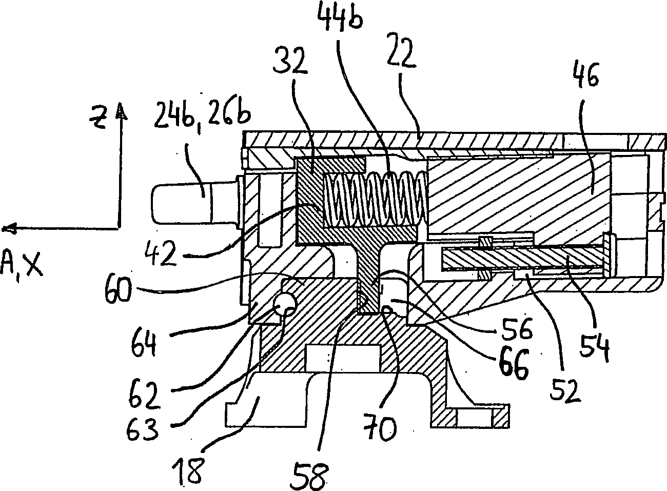
Unter Bezugnahme auch auf die
Eine Hauptachse A des Hauptkörpers
Wie in
Ein relativ zum Hauptkörper
In einer in den Zeichnungen nicht dargestellten Linearführung ist der Steuerkörper
An einem Stützabschnitt
An ihren dem Stützabschnitt
In der oben beschriebenen Weise ist der Steuerkörper
Wie in
Die Steuerkurve
Ein Sicherungsstift
An einem oberen, hinteren Abschnitt des Zapfens
Unter zusätzlicher Bezugnahme auf die
Gleichzeitig drücken die Federn
Wenn, beispielsweise während eines Sturzes, auf den Skischuh
Bei weiterer Bewegung des Skischuhs gleiten schließlich die vorderen Enden
Wenn, z. B. im Falle eines Sturzes, auf den Skischuh
Das Auslöseverhalten und insbesondere das für eine Seitenauslösung zu überwindende Mz-Auslösedrehmoment hängt ab von der Form der Steuerkurve
Aus der vorstehenden Beschreibung des Ausführungsbeispiels ist deutlich geworden, dass die Frontalauslösung und die Seitenauslösung eine gemeinsame Kraftquelle in Form beispielsweise zweier parallel angeordneter Federn
Eine aus den Federn
ZITATE ENTHALTEN IN DER BESCHREIBUNG QUOTES INCLUDE IN THE DESCRIPTION
Diese Liste der vom Anmelder aufgeführten Dokumente wurde automatisiert erzeugt und ist ausschließlich zur besseren Information des Lesers aufgenommen. Die Liste ist nicht Bestandteil der deutschen Patent- bzw. Gebrauchsmusteranmeldung. Das DPMA übernimmt keinerlei Haftung für etwaige Fehler oder Auslassungen.This list of the documents listed by the applicant has been generated automatically and is included solely for the better information of the reader. The list is not part of the German patent or utility model application. The DPMA assumes no liability for any errors or omissions.
Zitierte PatentliteraturCited patent literature
- WO 2009/105866 A1 [0003] WO 2009/105866 A1 [0003]
- EP 0199098 A2 [0004] EP 0199098 A2 [0004]
- AT 402020 B [0018] AT 402020 B [0018]
Claims (13)
Priority Applications (2)
| Application Number | Priority Date | Filing Date | Title |
|---|---|---|---|
| DE102010028764A DE102010028764A1 (en) | 2010-05-07 | 2010-05-07 | Heel unit for a binding, in particular touring ski binding |
| EP11164953.9A EP2384794B1 (en) | 2010-05-07 | 2011-05-05 | Heel unit for a binding, in particular touring-ski binding |
Applications Claiming Priority (1)
| Application Number | Priority Date | Filing Date | Title |
|---|---|---|---|
| DE102010028764A DE102010028764A1 (en) | 2010-05-07 | 2010-05-07 | Heel unit for a binding, in particular touring ski binding |
Publications (1)
| Publication Number | Publication Date |
|---|---|
| DE102010028764A1 true DE102010028764A1 (en) | 2011-11-10 |
Family
ID=44484881
Family Applications (1)
| Application Number | Title | Priority Date | Filing Date |
|---|---|---|---|
| DE102010028764A Ceased DE102010028764A1 (en) | 2010-05-07 | 2010-05-07 | Heel unit for a binding, in particular touring ski binding |
Country Status (2)
| Country | Link |
|---|---|
| EP (1) | EP2384794B1 (en) |
| DE (1) | DE102010028764A1 (en) |
Cited By (5)
| Publication number | Priority date | Publication date | Assignee | Title |
|---|---|---|---|---|
| DE202013009786U1 (en) * | 2013-11-29 | 2015-03-02 | Salewa Sport Ag | Slide board binding with two interconnected housing parts |
| EP3453433A1 (en) * | 2017-09-07 | 2019-03-13 | MARKER Deutschland GmbH | Heel binding with a functional element |
| DE102013224576B4 (en) | 2013-11-29 | 2019-03-28 | Salewa Sport Ag | Slide board binding with pivot bearing |
| EP4147757A1 (en) | 2021-09-13 | 2023-03-15 | Salewa Sport AG | Heel unit for a sliding board binding with a frontal release arrangement comprising a torsion spring |
| DE102024129167A1 (en) | 2024-10-09 | 2026-04-09 | Salewa Sport Ag | Heel unit for a touring binding |
Families Citing this family (12)
| Publication number | Priority date | Publication date | Assignee | Title |
|---|---|---|---|---|
| ITTO20120046A1 (en) * | 2012-01-21 | 2013-07-22 | Stefano Maruelli | LOCKING SYSTEM |
| ITTO20120146A1 (en) * | 2012-02-20 | 2013-08-21 | Marco Rigat | ROTARY TALLONIE |
| DE202012002705U1 (en) * | 2012-03-14 | 2013-06-17 | Salewa Sport Ag | Heel unit for a touring binding |
| ITTO20130949A1 (en) * | 2013-11-22 | 2015-05-23 | Stefano Maruelli | IMPROVED ANTI-ROTATION DEVICE |
| FR3025435B1 (en) | 2014-09-04 | 2016-09-02 | Salomon Sas | DETACHABLE ATTACHMENT |
| FR3026311A1 (en) | 2014-09-26 | 2016-04-01 | Salomon Sas | TALONNIERE FIXING A SHOE ON A BOARD OF SLIDING |
| EP3266504A1 (en) | 2016-07-07 | 2018-01-10 | Fritschi AG - Swiss Bindings | Ski binding |
| US10463946B2 (en) | 2017-06-07 | 2019-11-05 | G3 Genuine Guide Gear Inc. | Touring binding heel unit |
| US10315099B2 (en) | 2017-10-31 | 2019-06-11 | G3 Genuine Guide Gear Inc. | Lightweight touring binding heel unit |
| DE102020205754A1 (en) * | 2020-05-07 | 2021-11-11 | Salewa Sport Ag | HEEL UNIT FOR A SKI BINDING |
| DE102022106276A1 (en) * | 2022-03-17 | 2023-09-21 | Salewa Sport Ag | Heel unit for a sliding board binding with Mz release via cam body |
| FR3165186A1 (en) * | 2024-07-30 | 2026-02-06 | Felisaz S.A.S. | Heel piece for ski touring with release mechanism |
Citations (6)
| Publication number | Priority date | Publication date | Assignee | Title |
|---|---|---|---|---|
| FR2511602A1 (en) * | 1981-08-20 | 1983-02-25 | Salomon & Fils F | Ski safety binding with clamp articulated on body - has circular section axle held by extensions of body and centred by piston and spring assembly |
| EP0199098A2 (en) | 1985-03-25 | 1986-10-29 | Fritz Dipl.-Ing. Barthel | Cross-country ski binding |
| EP0519243A1 (en) * | 1991-06-21 | 1992-12-23 | Fritz Dipl.-Ing. Barthel | Jaw-irons for touring ski bindings |
| AT402020B (en) | 1993-08-19 | 1997-01-27 | Barthel Fritz | Heel jaw for a ski binding |
| EP0754079B1 (en) * | 1995-02-01 | 1999-04-28 | Fritschi Ag, Apparatebau | Ski binding |
| WO2009105866A1 (en) | 2008-02-29 | 2009-09-03 | G3 Genuine Guide Gear Inc. | Heel unit for alpine touring binding |
Family Cites Families (2)
| Publication number | Priority date | Publication date | Assignee | Title |
|---|---|---|---|---|
| DE3141021A1 (en) * | 1981-10-15 | 1983-04-28 | Etablissements François Salomon et Fils, 74011 Annecy, Haute-Savoie | Safety ski binding |
| EP2181736B1 (en) * | 2008-10-31 | 2012-08-08 | Rottefella AS | Heel binding with two release directions |
-
2010
- 2010-05-07 DE DE102010028764A patent/DE102010028764A1/en not_active Ceased
-
2011
- 2011-05-05 EP EP11164953.9A patent/EP2384794B1/en active Active
Patent Citations (6)
| Publication number | Priority date | Publication date | Assignee | Title |
|---|---|---|---|---|
| FR2511602A1 (en) * | 1981-08-20 | 1983-02-25 | Salomon & Fils F | Ski safety binding with clamp articulated on body - has circular section axle held by extensions of body and centred by piston and spring assembly |
| EP0199098A2 (en) | 1985-03-25 | 1986-10-29 | Fritz Dipl.-Ing. Barthel | Cross-country ski binding |
| EP0519243A1 (en) * | 1991-06-21 | 1992-12-23 | Fritz Dipl.-Ing. Barthel | Jaw-irons for touring ski bindings |
| AT402020B (en) | 1993-08-19 | 1997-01-27 | Barthel Fritz | Heel jaw for a ski binding |
| EP0754079B1 (en) * | 1995-02-01 | 1999-04-28 | Fritschi Ag, Apparatebau | Ski binding |
| WO2009105866A1 (en) | 2008-02-29 | 2009-09-03 | G3 Genuine Guide Gear Inc. | Heel unit for alpine touring binding |
Cited By (5)
| Publication number | Priority date | Publication date | Assignee | Title |
|---|---|---|---|---|
| DE202013009786U1 (en) * | 2013-11-29 | 2015-03-02 | Salewa Sport Ag | Slide board binding with two interconnected housing parts |
| DE102013224576B4 (en) | 2013-11-29 | 2019-03-28 | Salewa Sport Ag | Slide board binding with pivot bearing |
| EP3453433A1 (en) * | 2017-09-07 | 2019-03-13 | MARKER Deutschland GmbH | Heel binding with a functional element |
| EP4147757A1 (en) | 2021-09-13 | 2023-03-15 | Salewa Sport AG | Heel unit for a sliding board binding with a frontal release arrangement comprising a torsion spring |
| DE102024129167A1 (en) | 2024-10-09 | 2026-04-09 | Salewa Sport Ag | Heel unit for a touring binding |
Also Published As
| Publication number | Publication date |
|---|---|
| EP2384794B1 (en) | 2014-09-10 |
| EP2384794A1 (en) | 2011-11-09 |
Similar Documents
| Publication | Publication Date | Title |
|---|---|---|
| EP2384794B1 (en) | Heel unit for a binding, in particular touring-ski binding | |
| DE102012201816B4 (en) | Front unit for a gliding board binding having first and second engagement means | |
| DE202009019128U1 (en) | Toe unit for touring ski binding | |
| DE202011110813U1 (en) | automatic heel | |
| DE202009019109U1 (en) | Heel unit for touring ski binding | |
| DE202011110534U1 (en) | touring binding | |
| EP2666525B1 (en) | Heel binding unit with climbing wedge and ski-brake assembly | |
| DE102009051185A1 (en) | Ski binding with a positioning and fixing device for the back body | |
| EP2452731B1 (en) | Touring binding with release mechanism and locking mechanism | |
| EP3702005A1 (en) | Heelholder | |
| EP3974039A1 (en) | Brake assembly for a cross country ski binding | |
| DE102013204065B4 (en) | Buttocks with a ski brake for a ski touring binding | |
| EP3120903A1 (en) | Heel unit | |
| AT506526B1 (en) | FRONT BAKING OF A SAFETY CHAIN | |
| DE102013224574A1 (en) | Heel unit for touring binding and touring binding | |
| EP3517188B1 (en) | Front unit for a slide board | |
| EP4147757B1 (en) | Heel unit for a sliding board binding with a frontal release arrangement comprising a torsion spring | |
| DE69602509T2 (en) | Shoe retention device on a snowboard or ski or the like | |
| EP2821114B1 (en) | Safety ski binding system | |
| DE102022130901A1 (en) | Front unit with lowerable holding device | |
| EP4257212B1 (en) | Heel unit for a gliding board binding with mz release via cam bodies | |
| EP0547531B1 (en) | Front jaw | |
| AT410176B (en) | BINDING CONSTRUCTION | |
| EP3714952A1 (en) | Braking device | |
| DE2429610B2 (en) | Safety ski bindings |
Legal Events
| Date | Code | Title | Description |
|---|---|---|---|
| R163 | Identified publications notified | ||
| R012 | Request for examination validly filed | ||
| R002 | Refusal decision in examination/registration proceedings | ||
| R003 | Refusal decision now final |