DE102010005705A1 - Synchronization unit of a transmission - Google Patents

Synchronization unit of a transmission Download PDF

Info

Publication number
DE102010005705A1
DE102010005705A1 DE102010005705A DE102010005705A DE102010005705A1 DE 102010005705 A1 DE102010005705 A1 DE 102010005705A1 DE 102010005705 A DE102010005705 A DE 102010005705A DE 102010005705 A DE102010005705 A DE 102010005705A DE 102010005705 A1 DE102010005705 A1 DE 102010005705A1
Authority
DE
Germany
Prior art keywords
synchronizer
synchronization unit
synchronizer ring
axial
unit according
Prior art date
Legal status (The legal status is an assumption and is not a legal conclusion. Google has not performed a legal analysis and makes no representation as to the accuracy of the status listed.)
Granted
Application number
DE102010005705A
Other languages
German (de)
Other versions
DE102010005705B4 (en
Inventor
Erol 74074 Ledetzky
Current Assignee (The listed assignees may be inaccurate. Google has not performed a legal analysis and makes no representation or warranty as to the accuracy of the list.)
Hoerbiger Antriebstechnik Holding GmbH
Original Assignee
Hoerbiger Antriebstechnik 86956 GmbH
Hoerbiger and Co
Hoerbiger Antriebstechnik Holding GmbH
Priority date (The priority date is an assumption and is not a legal conclusion. Google has not performed a legal analysis and makes no representation as to the accuracy of the date listed.)
Filing date
Publication date
Application filed by Hoerbiger Antriebstechnik 86956 GmbH, Hoerbiger and Co, Hoerbiger Antriebstechnik Holding GmbH filed Critical Hoerbiger Antriebstechnik 86956 GmbH
Priority to DE102010005705.3A priority Critical patent/DE102010005705B4/en
Priority to PCT/EP2010/001982 priority patent/WO2010108697A1/en
Priority to EP10711351.6A priority patent/EP2411692B1/en
Publication of DE102010005705A1 publication Critical patent/DE102010005705A1/en
Application granted granted Critical
Publication of DE102010005705B4 publication Critical patent/DE102010005705B4/en
Active legal-status Critical Current
Anticipated expiration legal-status Critical

Links

Images

Classifications

    • FMECHANICAL ENGINEERING; LIGHTING; HEATING; WEAPONS; BLASTING
    • F16ENGINEERING ELEMENTS AND UNITS; GENERAL MEASURES FOR PRODUCING AND MAINTAINING EFFECTIVE FUNCTIONING OF MACHINES OR INSTALLATIONS; THERMAL INSULATION IN GENERAL
    • F16DCOUPLINGS FOR TRANSMITTING ROTATION; CLUTCHES; BRAKES
    • F16D23/00Details of mechanically-actuated clutches not specific for one distinct type
    • F16D23/02Arrangements for synchronisation, also for power-operated clutches
    • F16D23/04Arrangements for synchronisation, also for power-operated clutches with an additional friction clutch
    • F16D23/06Arrangements for synchronisation, also for power-operated clutches with an additional friction clutch and a blocking mechanism preventing the engagement of the main clutch prior to synchronisation
    • FMECHANICAL ENGINEERING; LIGHTING; HEATING; WEAPONS; BLASTING
    • F16ENGINEERING ELEMENTS AND UNITS; GENERAL MEASURES FOR PRODUCING AND MAINTAINING EFFECTIVE FUNCTIONING OF MACHINES OR INSTALLATIONS; THERMAL INSULATION IN GENERAL
    • F16DCOUPLINGS FOR TRANSMITTING ROTATION; CLUTCHES; BRAKES
    • F16D23/00Details of mechanically-actuated clutches not specific for one distinct type
    • F16D23/02Arrangements for synchronisation, also for power-operated clutches
    • F16D23/025Synchro rings
    • FMECHANICAL ENGINEERING; LIGHTING; HEATING; WEAPONS; BLASTING
    • F16ENGINEERING ELEMENTS AND UNITS; GENERAL MEASURES FOR PRODUCING AND MAINTAINING EFFECTIVE FUNCTIONING OF MACHINES OR INSTALLATIONS; THERMAL INSULATION IN GENERAL
    • F16DCOUPLINGS FOR TRANSMITTING ROTATION; CLUTCHES; BRAKES
    • F16D23/00Details of mechanically-actuated clutches not specific for one distinct type
    • F16D23/02Arrangements for synchronisation, also for power-operated clutches
    • F16D23/04Arrangements for synchronisation, also for power-operated clutches with an additional friction clutch
    • F16D23/06Arrangements for synchronisation, also for power-operated clutches with an additional friction clutch and a blocking mechanism preventing the engagement of the main clutch prior to synchronisation
    • F16D2023/0618Details of blocking mechanism comprising a helical spring loaded element, e.g. ball

Landscapes

  • Engineering & Computer Science (AREA)
  • General Engineering & Computer Science (AREA)
  • Mechanical Engineering (AREA)
  • Mechanical Operated Clutches (AREA)

Abstract

Die Erfindung betrifft eine Synchronisationseinheit (12) eines Getriebes (10), mit einem Synchronkörper (14), der auf einer Getriebewelle drehfest angebracht ist, einer Schaltmuffe (16), die relativ zum Synchronkörper (14) drehfest, aber axial verschieblich angeordnet ist, einem Synchronring (18, 20) zur Kopplung des Synchronkörpers (14) mit einem Gangrad (22, 24) des Getriebes (10) über eine Reibverbindung, sowie einer Vorsynchroneinheit (26), die an der Schaltmuffe (16) angreift und bei einer Axialverschiebung der Schaltmuffe (16) den Synchronring (18, 20) mit einer axialen Schaltkraft gegen das zu koppelnde Gangrad (22, 24) beaufschlagt, wobei die Vorsynchroneinheit (26) eine Kontaktfläche (28, 30) aufweist und sich über diese Kontaktfläche (28, 30) an einer Gegenfläche (32, 34) des Synchronrings (18, 20) in radialer Richtung (36) abstützt, und wobei sowohl die Kontaktfläche (28, 30) als auch die Gegenfläche (32, 34) gegenüber einer Axialrichtung (38) so geneigt sind, dass sich in axialer Richtung (38) vom Synchronkörper (14) zum Gangrad (22, 24) hin gesehen ihr radialer Abstand zu einer Getriebeachse (A) verringert.The invention relates to a synchronization unit (12) of a transmission (10), having a synchronizer body (14) mounted in a rotationally fixed manner on a transmission shaft, a selector sleeve (16) which is non-rotatably but axially displaceable relative to the synchronizer body (14). a synchronizer ring (18, 20) for coupling the synchronizer body (14) to a gear wheel (22, 24) of the transmission (10) via a frictional connection, and a pre-synchronizing unit (26) engaging the selector sleeve (16) and at an axial displacement the shift sleeve (16) acts on the synchronizer ring (18, 20) with an axial shift force against the gear wheel (22, 24) to be coupled, wherein the presynchronization unit (26) has a contact surface (28, 30) and extends over this contact surface (28, 28). 30) on a counter surface (32, 34) of the synchronizer ring (18, 20) in the radial direction (36) is supported, and wherein both the contact surface (28, 30) and the counter surface (32, 34) relative to an axial direction (38) so inclined, there As seen in the axial direction (38) from the synchronizer body (14) to the gear wheel (22, 24) towards their radial distance to a transmission axis (A) is reduced.

Figure 00000001
Figure 00000001

Description

Die Erfindung betrifft eine Synchronisationseinheit eines Getriebes, mit einem Synchronkörper, der auf einer Getriebewelle drehfest angebracht ist, einer Schaltmuffe, die relativ zum Synchronkörper drehfest, aber axial verschieblich angeordnet ist, einem Synchronring zur Kopplung des Synchronkörpers mit einem Gangrad des Getriebes über eine Reibverbindung, sowie einer Vorsynchroneinheit, die an der Schaltmuffe angreift und bei einer Axialverschiebung der Schaltmuffe den Synchronring mit einer axialen Schaltkraft gegen das zu koppelnde Gangrad beaufschlagt, wobei die Vorsynchroneinheit eine Kontaktfläche aufweist und sich über diese Kontaktfläche an einer Gegenfläche des Synchronrings in radialer Richtung abstützt.The invention relates to a synchronization unit of a transmission, with a synchronizer body which is rotatably mounted on a transmission shaft, a shift sleeve which is rotatably relative to the synchronizer body, but axially displaceable, a synchronizer ring for coupling the synchronizer body with a gear wheel of the transmission via a friction joint, and a Vorsynchroneinheit which engages the shift sleeve and acts on the synchronizer ring with an axial switching force against the gear wheel to be coupled in an axial displacement, wherein the Vorsynchroneinheit has a contact surface and is supported via this contact surface on a counter surface of the synchronizer ring in the radial direction.

Die DE 20 2009 004 325 U1 offenbart eine gattungsgemäße Synchronisationseinheit, bei der sich ein Synchronstein der Vorsynchroneinheit direkt auf einem Reibkonus des Synchronrings abstützt.The DE 20 2009 004 325 U1 discloses a generic synchronization unit in which a synchronizing block of the Vorsynchroneinheit is supported directly on a Reibkonus of the synchronizer ring.

Im Stand der Technik ergibt sich dabei das Problem, dass der Synchronring eine axiale Bewegungsfreiheit in Richtung zum Gangrad aufweist oder sogar durch eine radiale Vorspannung der Vorsynchroneinheit axial gegen ein dem Synchronring zugeordnetes Gangrad beaufschlagt ist. In einer nicht-geschalteten Neutralstellung des Getriebes kann es bei einer entsprechenden axialen Bewegung des Synchronrings zu einem Kontakt zwischen dem Synchronring und einer Reibfläche des Gangrads kommen, was zu unerwünschten Schleppmomenten führt, welche wiederum den Wirkungsgrad des Getriebes negativ beeinflussen.In the prior art, this results in the problem that the synchronizer ring has an axial freedom of movement in the direction of the gear wheel or even by a radial bias of the Vorsynchroneinheit is acted upon axially against a synchronizer ring associated with the gear wheel. In a non-switched neutral position of the transmission, it may come at a corresponding axial movement of the synchronizer ring to a contact between the synchronizer ring and a friction surface of the gear wheel, which leads to undesirable drag torque, which in turn adversely affect the efficiency of the transmission.

Aufgabe der Erfindung ist es, mit geringem Aufwand eine Synchronisationseinheit zu schaffen, welche in einer Neutralstellung des Getriebes ein verringertes Schleppmoment sowie eine axiale Mittenarretierung der Vorsynchroneinheit und der Schaltmuffe aufweist.The object of the invention is to provide a synchronization unit with little effort, which in a neutral position of the transmission has a reduced drag torque and an axial center locking of the Vorsynchroneinheit and the shift sleeve.

Erfindungsgemäß wird diese Aufgabe gelöst durch eine Synchronisationseinheit der eingangs genannten Art, bei der sowohl die Kontaktfläche als auch die Gegenfläche gegenüber einer Axialrichtung so geneigt sind, dass sich in axialer Richtung vom Synchronkörper zum Gangrad hin gesehen ihr radialer Abstand zu einer Getriebeachse verringert. Mit einer derartig geneigten Kontakt- bzw. Gegenfläche ist eine axiale Bewegung des Synchronrings in Richtung zu seinem zugeordneten Gangrad deutlich erschwert, wodurch unerwünschte Schleppmomente seltener auftreten und/oder betragsmäßig kleiner ausfallen. Dies trägt insgesamt zu einem besseren Wirkungsgrad des Getriebes und damit zu einer effizienteren Energienutzung bei, was sowohl ökonomisch als auch ökologisch vorteilhaft ist.According to the invention this object is achieved by a synchronization unit of the type mentioned, in which both the contact surface and the counter surface are inclined relative to an axial direction so that seen in the axial direction from the synchronizer body to the gear wheel towards their radial distance reduced to a transmission axis. With such an inclined contact or mating surface, an axial movement of the synchronizing ring in the direction of its associated gear wheel is made considerably more difficult, as a result of which undesired drag torques occur less frequently and / or are smaller in magnitude. Overall, this contributes to a better efficiency of the transmission and thus to a more efficient use of energy, which is both economically and ecologically advantageous.

Die Kontaktfläche und die Gegenfläche können im Wesentlichen parallel ausgerichtet sein, sodass sich die Vorsynchroneinheit flächig am Synchronring abstützt. Daraus resultiert eine geringere Materialbeanspruchung im Bereich der Kontaktstelle, was sich entsprechend positiv auf die Verschleißerscheinungen an den beteiligten Bauteilen auswirkt.The contact surface and the mating surface may be aligned substantially parallel, so that the Vorsynchroneinheit rests flat on the synchronizer ring. This results in a lower material stress in the region of the contact point, which has a correspondingly positive effect on the wear on the components involved.

Vorzugsweise ist die Vorsynchroneinheit vom Synchronkörper radial beabstandet. Dies ermöglicht ein ungehindertes, reibungsfreies „Umschlagen” der Vorsynchroneinheit, das heißt eine Bewegung der Vorsynchroneinheit relativ zum Synchronkörper in Umfangsrichtung.Preferably, the Vorsynchroneinheit is radially spaced from the synchronizer body. This allows unimpeded, frictionless "turning over" of the Vorsynchroneinheit, that is, a movement of the Vorsynchroneinheit relative to the synchronizer body in the circumferential direction.

In einer Ausführungsform umfasst die Vorsynchroneinheit ein Bauteil, an dem die Kontaktfläche ausgebildet ist, sowie ein Federelement, welches das Bauteil radial gegen den Synchronring beaufschlagt. Infolge der geneigten Kontakt- und Gegenfläche entsteht durch die radial ausgerichtete Federkraft eine axiale Kraftkomponente im Synchronring, welche den Synchronring axial vom zugeordneten Gangrad weg beaufschlagt. Somit trägt die Federkraft unmittelbar zu einer Minimierung der im Getriebe auftretenden Schleppmomente bei.In one embodiment, the Vorsynchroneinheit comprises a component on which the contact surface is formed, and a spring element which acts on the component radially against the synchronizer ring. As a result of the inclined contact and mating surface is formed by the radially aligned spring force an axial force component in the synchronizer ring, which acts on the synchronizer ring axially away from the associated gear. Thus, the spring force contributes directly to a minimization of the drag torques occurring in the transmission.

Vorzugsweise sind die Kontaktfläche und deren Gegenfläche in einem axialen Längsschnitt der Synchronisationseinheit als gerade Schnittlinien sichtbar, die mit der Axialrichtung einen Winkel α einschließen. Dieser Winkel α bestimmt die Größe der Axialkraftkomponente, welche beim radialen Abstützen der Vorsynchroneinheit in den Synchronring eingeleitet wird. Der Winkel α liegt vorzugsweise in einer Größenordnung von etwa 5° bis 20°, besonders bevorzugt bei 10° bis 15°.The contact surface and its mating surface are preferably visible in an axial longitudinal section of the synchronization unit as straight cut lines which enclose an angle α with the axial direction. This angle α determines the size of the Axialkraftkomponente, which is initiated in the radial support of the Vorsynchroneinheit in the synchronizer ring. The angle α is preferably on the order of about 5 ° to 20 °, more preferably 10 ° to 15 °.

In einer weiteren Ausführungsform der Synchronisationseinheit sind die Vorsynchroneinheit und der Synchronring in Umfangsrichtung im Wesentlichen spielfrei miteinander verbunden. Dadurch werden Klappergeräusche zwischen der Vorsynchroneinheit und dem Synchronring vermieden, was zu einem besonders geräuscharmen Betrieb der Synchronisationseinheit beiträgt.In a further embodiment of the synchronization unit, the presynchronization unit and the synchronizer ring are connected to each other in the circumferential direction substantially free of play. As a result, rattling noises between the Vorsynchroneinheit and the synchronizer ring are avoided, which contributes to a particularly quiet operation of the synchronization unit.

Bevorzugt weisen die Vorsynchroneinheit und der Synchronring einander zugeordnete Anschlagflächen zur Begrenzung einer axialen Relativbewegung auf.Preferably, the Vorsynchroneinheit and the synchronizer ring on each other associated stop surfaces for limiting an axial relative movement.

Darüber hinaus können der Synchronkörper und der Synchronring ebenfalls einander zugeordnete Anschlagflächen zur Begrenzung einer axialen Relativbewegung aufweisen. Zusammen mit der durch die Neigung der Kontakt- und Gegenflächen verursachten Axialkraftkomponente auf den Synchronring führen diese einander zugeordneten Anschlagflächen einerseits zu einer axialen Mittenarretierung der Vorsynchroneinheit und andererseits zu einer definierten „Entlüftungsstellung” des Synchronrings. Als Entlüftungsstellung des Synchronrings wird dabei eine axiale Synchronringposition bezeichnet, in der eine Reibfläche des Synchronrings von einer Reibfläche des Gangrads beabstandet ist, sodass sich „Luft” zwischen den Reibflächen befindet. Demzufolge treten in einer solchen Entlüftungsstellung des Synchronrings keine unerwünschten Schleppmomente, insbesondere hervorgerufen durch Schmier- und Kühlstoffe, im Getriebe auf.In addition, the synchronizer body and the synchronizer ring may also have associated stop surfaces for limiting an axial relative movement. Together with the Axialkraftkomponente caused by the inclination of the contact and mating surfaces on the synchronizer ring these mutually associated abutment surfaces on the one hand lead to an axial Mittenarretierung the Vorsynchroneinheit and on the other hand to a defined "venting position" of the synchronizer ring. As the venting position of the synchronizer ring while an axial synchronizer ring position is referred to, in which a friction surface of the synchronizer ring is spaced from a friction surface of the gear wheel, so that "air" is located between the friction surfaces. Consequently occur in such a vent position of the synchronizer ring no unwanted drag torque, in particular caused by lubricants and coolants in the transmission.

In einer Ausführungsform der Synchronisationseinheit kann der Synchronring eine radiale Außenseite aufweisen, die sich in axialer Richtung vom Synchronkörper zum Gangrad hin gesehen zunächst radial aufweitet und dann radial verjüngt. Diese Konstruktion ermöglicht eine besonders einfache Fertigung des Synchronrings.In one embodiment of the synchronization unit, the synchronizer ring may have a radial outer side, which, viewed axially in the axial direction from the synchronizer body to the gearwheel, initially widens radially and then tapers radially. This construction allows a particularly simple production of the synchronizer ring.

In einer anderen Ausführungsform ist an einem dem zugeordneten Gangrad zugewandten axialen Ende des Synchronrings ein in Richtung zum Synchronkörper abgewinkelter Abschnitt angeformt, der die Gegenfläche zum Abstützen der Vorsynchroneinheit aufweist. Ausgehend von herkömmlichen Synchronringen, wie sie beispielsweise bei sogenannten Borg-Warner-Synchronisierungen zum Einsatz kommen, sind bei dieser Konstruktion nur geringfügige konstruktive und fertigungstechnische Anpassungen notwendig, um eine vorteilhafte Reduktion der Schleppmomente zu erreichen.In another embodiment, an angled in the direction of the synchronizer body portion is integrally formed on one of the associated gear wheel facing axial end of the synchronizer ring having the opposite surface for supporting the Vorsynchroneinheit. Starting from conventional synchronizer rings, as used for example in so-called Borg-Warner synchronizers, only minor structural and manufacturing adjustments are necessary in this construction in order to achieve an advantageous reduction of the drag torques.

In einer Ausführungsform der Synchronisationseinheit weist der Synchronring eine Sperrverzahnung auf, die eine Axialbewegung der Schaltmuffe zum Gangrad hin freigeben oder sperren kann. Somit lässt sich die vorteilhafte Schleppmomentverringerung und Mittenarretierung gemäß der Erfindung auch bei Schaltgetrieben mit einem herkömmlichen Sperrmechanismus nach Borg-Warner einsetzen.In one embodiment of the synchronization unit, the synchronizer ring has a locking toothing, which can release or block an axial movement of the sliding sleeve towards the gear wheel. Thus, the advantageous Schleppmomentverringerung and Mittenarretierung according to the invention can also be used in manual transmissions with a conventional locking mechanism according to Borg-Warner.

Vorzugsweise ist dabei die Sperrverzahnung des Synchronrings in Umfangsrichtung gesehen im Bereich der abgewinkelten Abschnitte unterbrochen.Preferably, the locking teeth of the synchronizer ring in the circumferential direction is interrupted in the region of the angled portions.

In einer anderen Ausführungsform der Synchronisationseinheit umfasst die Vorsynchroneinheit eine Sperrverzahnung, die eine Axialbewegung der Schaltmuffe zum Gangrad hin freigeben oder sperren kann. Durch die Ausbildung der Sperrverzahnung an der Vorsynchroneinheit kann am Synchronring auf eine Sperrverzahnung verzichtet werden, wodurch sich der Synchronring deutlich einfacher und preiswerter herstellen lässt.In another embodiment of the synchronization unit, the Vorsynchroneinheit comprises a locking toothing, which can release or lock an axial movement of the shift sleeve to the gear wheel. Due to the design of the locking teeth on the Vorsynchroneinheit can be dispensed with the locking ring on the synchronizer ring, which can be much easier and cheaper to produce the synchronizer ring.

In einer weiteren Ausführungsform ist die Vorsynchroneinheit eine Sperrkeilsynchronisationsbaugruppe, mit einem Synchronstein, der sich in radialer Richtung am Synchronring abstützt, einem Federelement, das sich am Synchronstein abstützt, und einem Sperrstein, der durch das Federelement radial gegen die Schaltmuffe beaufschlagt ist, wobei der Sperrstein eine Axialbewegung der Schaltmuffe zum Gangrad hin freigeben oder sperren kann. Bei dieser Konstruktion der Synchronisationseinheit kann sowohl auf eine Sperrverzahnung am Synchronring als auch auf eine Sperrverzahnung an der Vorsynchroneinheit verzichtet werden. Somit lässt sich auch diese Synchronisationseinheit besonders einfach und kostengünstig herstellen.In another embodiment, the Vorsynchroneinheit is a Sperrkeilsynchronisationsbaugruppe, with a synchronous stone, which is supported in the radial direction of the synchronizer ring, a spring element which is supported on the synchronizer stone, and a blocking stone, which is acted upon by the spring element radially against the sliding sleeve, wherein the blocking stone can release or lock an axial movement of the shift sleeve towards the gear wheel. In this construction, the synchronization unit can be dispensed with both a locking teeth on the synchronizer ring and on a locking teeth on the Vorsynchroneinheit. Thus, this synchronization unit can be produced particularly easily and inexpensively.

Insbesondere ist in axialer Richtung auf beiden Seiten des Synchronkörpers ein Synchronring angeordnet. Hieraus ergibt sich eine besonders vorteilhafte Lagerung der Vorsynchroneinheit, die sich symmetrisch auf beiden Synchronringen abstützt.In particular, a synchronizer ring is arranged in the axial direction on both sides of the synchronizer body. This results in a particularly advantageous storage of the Vorsynchroneinheit, which is supported symmetrically on both synchronizer rings.

Vorzugsweise sind die beiden Synchronringe durch die Vorsynchroneinheit in Umfangsrichtung im Wesentlichen spielfrei gekoppelt. Infolge dieser Kopplung reduzieren sich die im Betrieb auftretenden Klappergeräusche zwischen den Synchronringen und dem Synchronkörper erheblich.Preferably, the two synchronizer rings are coupled by the Vorsynchroneinheit in the circumferential direction substantially free of play. As a result of this coupling, the rattling noise occurring during operation between the synchronizer rings and the synchronizer body reduce considerably.

Besonders bevorzugt sind die beiden Synchronringe in einer nicht-geschalteten Neutralstellung des Schaltgetriebes durch die Vorsynchroneinheit axial aufeinander zu beaufschlagt. Diese vorteilhafte Beaufschlagung der Synchronringe in ihre „entlüfteten” Stellungen lässt sich mit geringem Aufwand beispielsweise dadurch realisieren, dass die Vorsynchroneinheit eine radiale Vorspannung sowie für jeden Synchronring wenigstens eine Kontaktfläche aufweist, die in geeigneter Weise geneigt ist.Particularly preferably, the two synchronizing rings in a non-switched neutral position of the gearbox by the Vorsynchroneinheit axially acted upon each other. This advantageous loading of the synchronizer rings in their "vented" positions can be realized with little effort, for example, by the fact that the Vorsynchroneinheit has a radial bias and for each synchronizer ring at least one contact surface which is inclined in a suitable manner.

Weitere Merkmale und Vorteile der Erfindung ergeben sich aus der nachfolgenden Beschreibung bevorzugter Ausführungsformen unter Bezugnahme auf die Zeichnungen. In diesen zeigen:Further features and advantages of the invention will become apparent from the following description of preferred embodiments with reference to the drawings. In these show:
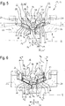
1 einen schematischen, axialen Längsschnitt längs der Linie I-I in 3 durch ein Schaltgetriebe mit einer erfindungsgemäßen Synchronisationseinheit gemäß einer ersten Ausführungsform in einer axial mittigen Neutralstellung; 1 a schematic, axial longitudinal section along the line II in 3 by a transmission with a synchronization unit according to the invention according to a first embodiment in an axially central neutral position;

2 einen weiteren axialen Längsschnitt durch das Schaltgetriebe gemäß 1 in einer axial ausgelenkten Stellung; 2 a further axial longitudinal section through the transmission according to 1 in an axially deflected position;

3 einen schematischen Querschnitt längs der Linie III-III in 1 durch ein Detail der Synchronisationseinheit gemäß 1 im Bereich einer Vorsynchroneinheit in einer Freigabestellung; 3 a schematic cross section along the line III-III in 1 by a detail of the synchronization unit according to 1 in the region of a Vorsynchroneinheit in a release position;

4 einen weiteren schematischen Querschnitt durch ein Detail der Synchronisationseinheit gemäß 1 im Bereich einer Vorsynchroneinheit in einer Sperrstellung; 4 a further schematic cross section through a detail of the synchronization unit according to 1 in the region of a Vorsynchroneinheit in a blocking position;

5 einen schematischen, axialen Längsschnitt durch ein Schaltgetriebe mit einer erfindungsgemäßen Synchronisationseinheit gemäß einer zweiten Ausführungsform in einer axial mittigen Neutralstellung; 5 a schematic, axial longitudinal section through a transmission with a synchronization unit according to the invention according to a second embodiment in an axially central neutral position;

6 einen weiteren axialen Längsschnitt durch das Schaltgetriebe gemäß 5 in einer axial ausgelenkten Stellung; 6 a further axial longitudinal section through the transmission according to 5 in an axially deflected position;

7 einen schematischen, axialen Längsschnitt durch ein Schaltgetriebe mit einer erfindungsgemäßen Synchronisationseinheit gemäß einer dritten Ausführungsform in einer axial mittigen Neutralstellung; und 7 a schematic, axial longitudinal section through a transmission with a synchronization unit according to the invention according to a third embodiment in an axially central neutral position; and

8 einen schematischen, axialen Längsschnitt durch ein Schaltgetriebe mit einer erfindungsgemäßen Synchronisationseinheit gemäß einer vierten Ausführungsform in einer axial mittigen Neutralstellung. 8th a schematic, axial longitudinal section through a transmission with a synchronization unit according to the invention according to a fourth embodiment in an axially central neutral position.

Die 1 zeigt einen Schnitt durch ein Schaltgetriebe 10 eines Fahrzeugs längs einer Getriebeachse A, mit einer Synchronisationseinheit 12 gemäß einer ersten Ausführungsform. Die Synchronisationseinheit 12 umfasst dabei einen Synchronkörper 14, der auf einer um die Getriebeachse A rotierbaren (nicht dargestellten) Getriebewelle drehfest angebracht ist, eine Schaltmuffe 16, die relativ zum Synchronkörper 14 drehfest, aber axial verschieblich angeordnet ist, einen Synchronring 18, 20 zur Kopplung des Synchronkörpers 14 mit einem Gangrad 22, 24 des Schaltgetriebes 10 über eine Reibverbindung, sowie eine Vorsynchroneinheit 26, die an der Schaltmuffe 16 angreift und bei einer Axialverschiebung der Schaltmuffe 16 den Synchronring 18, 20 mit einer axialen Schaltkraft gegen das zu koppelnde Gangrad 22, 24 beaufschlagt.The 1 shows a section through a manual transmission 10 a vehicle along a transmission axis A, with a synchronization unit 12 according to a first embodiment. The synchronization unit 12 includes a synchronous body 14 , which is rotatably mounted on a rotatable about the transmission axis A (not shown) gear shaft, a shift sleeve 16 that are relative to the synchronizer body 14 rotatably but axially displaceable, a synchronizer ring 18 . 20 for coupling the synchronizer body 14 with a gear wheel 22 . 24 of the gearbox 10 via a friction connection, as well as a Vorsynchroneinheit 26 attached to the sliding sleeve 16 engages and at an axial displacement of the sliding sleeve 16 the synchronizer ring 18 . 20 with an axial switching force against the gear wheel to be coupled 22 . 24 applied.

Die Vorsynchroneinheit 26 weist radial innenseitige Kontaktflächen 28, 30 auf und stützt sich über diese Kontaktflächen 28, 30 an Gegenflächen 32, 34 des Synchronrings 18, 20 in radialer Richtung 36 ab, wobei sowohl die Kontaktflächen 28, 30 als auch die Gegenflächen 32, 34 gegenüber einer Axialrichtung 38 so geneigt sind, dass sich in axialer Richtung 38 vom Synchronkörper 14 zum Gangrad 22, 24 hin gesehen ihr radialer Abstand s zur Drehachse A verringert.The presynchronizing unit 26 has radially inside contact surfaces 28 . 30 on and relies on these contact surfaces 28 . 30 on mating surfaces 32 . 34 of the synchronizer ring 18 . 20 in the radial direction 36 with both the contact surfaces 28 . 30 as well as the counter surfaces 32 . 34 opposite to an axial direction 38 are inclined so that in the axial direction 38 from the synchronizer body 14 to the gear wheel 22 . 24 seen her radial distance s to the axis of rotation A decreases.

Im vorliegenden Ausführungsbeispiel des Schaltgetriebes 10 sind in axialer Richtung 38 auf beiden Seiten des Synchronkörpers 14 jeweils ein Synchronring 18, 20 und ein Gangrad 22, 24 angeordnet. Die Vorsynchroneinheit 26 weist sowohl eine Kontaktfläche 28 für den in 1 links dargestellten Synchronring 18 als auch eine Kontaktfläche 30 für den in 1 rechts dargestellten Synchronring 20 auf und stützt sich somit symmetrisch an beiden Synchronringen 18, 20 radial nach innen ab. An beiden Synchronringen 18, 20 sind entsprechende Gegenflächen 32, 34 ausgebildet, an denen die Kontaktflächen 28, 30 der Vorsynchroneinheit 26 angreifen.In the present embodiment of the gearbox 10 are in the axial direction 38 on both sides of the synchronizer body 14 one synchronizer ring each 18 . 20 and a gear wheel 22 . 24 arranged. The presynchronizing unit 26 has both a contact surface 28 for the in 1 shown on the left synchronizer ring 18 as well as a contact surface 30 for the in 1 right side synchronizer ring 20 on and thus supports symmetrically on both synchronizer rings 18 . 20 radially inward. At both synchronizer rings 18 . 20 are corresponding counter surfaces 32 . 34 formed at which the contact surfaces 28 . 30 the pre-sync unit 26 attack.

Jede Kontaktfläche 28, 30 erstreckt sich im Wesentlichen parallel zu ihrer jeweiligen Gegenfläche 32, 34, sodass sich die Vorsynchroneinheit 26 flächig an den Synchronringen 18, 20 abstützt. Die Kontakt- und Gegenflächen 28, 30 bzw. 32, 34 sind im Wesentlichen Kegelabschnittsflächen und daher im Längsschnitt der 1 als gerade Schnittlinien sichtbar, die mit der Axialrichtung 38 einen Winkel α einschließen. Dieser Neigungswinkel α beträgt etwa 5° bis 20°, vorzugsweise 10° bis 15° und bestimmt letztlich eine Axialkraftkomponente FA zur Mittenarretierung der Vorsynchroneinheit 26 sowie zur Beaufschlagung der Synchronringe 18, 20 weg von Reibflächen 44 ihrer zugeordneten Gangräder 22, 24 (vgl. auch 2).Every contact surface 28 . 30 extends substantially parallel to its respective mating surface 32 . 34 so that the pre-sync unit 26 flat on the synchronizer rings 18 . 20 supported. The contact and counter surfaces 28 . 30 respectively. 32 . 34 are essentially conical section surfaces and therefore in longitudinal section of the 1 visible as straight cut lines, with the axial direction 38 include an angle α. This inclination angle α is about 5 ° to 20 °, preferably 10 ° to 15 ° and ultimately determines an axial force component F A for center locking the Vorsynchroneinheit 26 and for acting on the synchronizer rings 18 . 20 away from friction surfaces 44 their associated gear wheels 22 . 24 (see also 2 ).

In dieser ersten Ausführungsform der Synchronisationseinheit 12 sind an einem dem zugeordneten Gangrad 22, 24 zugewandten axialen Ende der Synchronringe 18, 20 in Richtung zum Synchronkörper 14 im Querschnitt betrachtet C- oder V-förmig abgewinkelte Abschnitte 40 vorgesehen, welche die Gegenflächen 32, 34 zum Abstützen der Vorsynchroneinheit 26 aufweisen. Die Abschnitte 40 sind einstückig mit den Synchronringen 18, 20 ausgebildet, also beispielsweise bei einem Sinterring bereits während des Sinterns angeformt oder bei einem Blechring gestanzt und nachträglich umgeformt.In this first embodiment of the synchronization unit 12 are at one of the associated gear wheel 22 . 24 facing axial end of the synchronizer rings 18 . 20 towards the synchronizer body 14 viewed in cross-section C- or V-shaped angled sections 40 provided, which the mating surfaces 32 . 34 for supporting the Vorsynchroneinheit 26 exhibit. The sections 40 are integral with the synchronizer rings 18 . 20 formed, so for example, in a sintered ring already formed during sintering or punched at a metal ring and subsequently formed.

Gemäß 1 befindet sich die Synchronisationseinheit 12 in einer nicht-geschalteten Neutralstellung, in der die Schaltmuffe 16 und die Vorsynchroneinheit 26 axial mittig zum Synchronkörper 14 ausgerichtet sind. Die an den Synchronringen 18, 20 vorgesehenen Reibflächen 42 sind in dieser axialen Neutralstellung von den angrenzenden Reibflächen 44 der Gangräder 22, 24 beabstandet. Mit anderen Worten sind die Synchronringe 18, 20 in dieser Neutralstellung „entlüftet”, da ein Abstand, also „Luft” zwischen den Reibflächen 42, 44 vorhanden ist.According to 1 is the synchronization unit 12 in a non-switched neutral position in which the shift sleeve 16 and the pre-sync unit 26 axially centered to the synchronizer body 14 are aligned. The on the synchronizer rings 18 . 20 provided friction surfaces 42 are in this axial neutral position of the adjacent friction surfaces 44 the gear wheels 22 . 24 spaced. In other words, the synchronizer rings 18 . 20 in this neutral position "vented", as a distance, so "air" between the friction surfaces 42 . 44 is available.

Die Vorsynchroneinheit 26 umfasst in der ersten Ausführungsform der Synchronisationseinheit 12 ein Druckstück 46, an dem die Kontaktflächen 28, 30 ausgebildet sind, ein Kraftübertragungselement 48, das üblicherweise eine Stahlkugel ist, und ein Federelement 50, welches das Druckstück 46 radial nach innen und das Kraftübertragungselement 48 radial nach außen beaufschlagt. Die Vorsynchroneinheit 26 liegt also radial vorgespannt zwischen der Schaltmuffe 16 und den Synchronringen 18, 20, da das in 1 als Schraubendruckfeder ausgeführte Federelement 50 das Druckstück 46 gegen die Abschnitte 40 der Synchronringe 18, 20 und das Kraftübertragungselement 48 gegen die Schaltmuffe 16 presst. Dementsprechend muss eine auf das Druckstück 46 wirkende, radiale Federkraft FR über die Kontaktflächen 28, 30 und die Gegenflächen 32, 34 in die Synchronringe 18, 20 eingeleitet werden.The presynchronizing unit 26 comprises in the first embodiment of the synchronization unit 12 a pressure piece 46 at which the contact surfaces 28 . 30 are formed, a power transmission element 48 , which is usually a steel ball, and a spring element 50 which is the pressure piece 46 radially inward and the power transmission element 48 acted upon radially outward. The presynchronizing unit 26 So is radially biased between the shift sleeve 16 and the synchronizer rings 18 . 20 because the in 1 designed as a helical compression spring spring element 50 the pressure piece 46 against the sections 40 the synchronizer rings 18 . 20 and the power transmission element 48 against the shift sleeve 16 pressed. Accordingly, one on the pressure piece 46 acting, radial spring force FR over the contact surfaces 28 . 30 and the mating surfaces 32 . 34 into the synchronizer rings 18 . 20 be initiated.

Infolge der Neigung der Kontakt- und Gegenflächen 28, 30, 32, 34 gegenüber der Axialrichtung 38 entsteht dabei jeweils eine axiale Kraftkomponente FA 46 am Druckstück 46 und eine axiale Kraftkomponente FA 18 und FA 20 an den Synchronringen 18 bzw. 20. Die axialen Kraftkomponenten FA 18 und FA 20 beaufschlagen die Synchronringe 18, 20 aufeinander zu, also in die entlüftete Stellung gemäß 1.Due to the inclination of the contact and mating surfaces 28 . 30 . 32 . 34 opposite to the axial direction 38 In each case, an axial force component F A 46 arises on the pressure piece 46 and an axial force component F A 18 and F A 20 on the synchronizer rings 18 respectively. 20 , The axial force components F A 18 and F A 20 act on the synchronizer rings 18 . 20 towards each other, ie in the vented position according to 1 ,

Das Druckstück 46 der Vorsynchroneinheit 26 ist aufgrund der im Betrieb des Schaltgetriebes 10 auftretenden Beanspruchungen üblicherweise als Sinterteil oder Blechteil gefertigt, kann alternativ aber auch aus einem widerstandsfähigen, gegebenenfalls faserverstärkten Kunststoff hergestellt sein.The pressure piece 46 the pre-sync unit 26 is due to the operation of the gearbox 10 occurring stresses usually made as a sintered part or sheet metal part, but may alternatively be made of a durable, optionally fiber-reinforced plastic.

Die Vorsynchroneinheit 26, genauer das Druckstück 46 der Vorsynchroneinheit 26, und die Synchronringe 18, 20, genauer die Abschnitte 40 der Synchronringe 18, 20, weisen einander zugeordnete Anschlagflächen 52, 52' zur Begrenzung einer axialen Relativbewegung auf. Darüber hinaus weisen der Synchronkörper 14 und die Synchronringe 18, 20 ebenfalls einander zugeordnete Anschlagflächen 54, 54' zur Begrenzung einer axialen Relativbewegung auf. Idealerweise liegen in der Neutralstellung der Synchronisationseinheit 12 gemäß 1 alle einander zugeordneten Anschlagflächen 52, 52'; 54, 54' aneinander an. Die Synchronringe 18, 20 sind dabei axial aufeinander zu beaufschlagt und werden mit ihren Anschlagflächen 52', 54' gegen die zugeordneten Anschlagflächen 52, 54 des Druckstücks 46 und des Synchronkörpers 14 gedrückt. Infolge dieser Beaufschlagung der Synchronringe 18, 20 in ihre jeweilige Entlüftungsstellung werden unerwünschte Schleppmomente im Getriebe 10 minimiert.The presynchronizing unit 26 , more precisely, the pressure piece 46 the pre-sync unit 26 , and the synchronizer rings 18 . 20 , more precisely the sections 40 the synchronizer rings 18 . 20 , have associated stop surfaces 52 . 52 ' for limiting an axial relative movement. In addition, have the synchronizer body 14 and the synchronizer rings 18 . 20 also associated with each other stop surfaces 54 . 54 ' for limiting an axial relative movement. Ideally, they are in the neutral position of the synchronization unit 12 according to 1 all mutually associated stop surfaces 52 . 52 '; 54 . 54 ' to each other. The synchronizer rings 18 . 20 are acted upon axially to each other and are with their stop surfaces 52 ' . 54 ' against the associated stop surfaces 52 . 54 of the pressure piece 46 and the synchronizer body 14 pressed. As a result of this admission of synchronizer rings 18 . 20 in their respective vent position unwanted drag torque in the transmission 10 minimized.

Ausgehend von der nicht-geschalteten Neutralstellung in 1 ist die Synchronisationseinheit 12 in 2 zum Beispiel durch eine zufällige Getriebeanregung axial ausgelenkt. Beispielhaft ist hier die Vorsynchroneinheit 26 und über die Anschlagflächen 52, 52' auch der linke Synchronring 18 axial nach links verschoben. Infolge dieser Axialverschiebung bewegen sich die Reibflächen 42, 44 des Synchronrings 18 und des Gangrads 22 aufeinander zu, sodass es zu einer Angleichung der Differenzdrehzahlen zwischen dem Gangrad 22, 24 und dem Synchronkörper 14 kommen kann.Starting from the non-switched neutral position in 1 is the synchronization unit 12 in 2 For example, by a random gear excitation axially deflected. Exemplary here is the Vorsynchroneinheit 26 and over the stop surfaces 52 . 52 ' also the left synchronizer ring 18 moved axially to the left. As a result of this axial displacement, the friction surfaces move 42 . 44 of the synchronizer ring 18 and the gear wheel 22 towards each other, so that there is an approximation of the differential speeds between the gear wheel 22 . 24 and the synchronizer body 14 can come.

Durch die Axialverschiebung entfernen sich gleichzeitig die Anschlagflächen 54, 54' zwischen dem (linken) Synchronring 18 und dem Synchronkörper 14 sowie die Anschlagflächen 52, 52' zwischen der Vorsynchroneinheit 26 und dem (rechten) Synchronring 20. Der Synchronring 20 wird dabei durch die axiale Kraftkomponente FA 20 axial in Richtung zum Synchronkörper 14 beaufschlagt, wobei eine entsprechende Synchronringverschiebung durch die Anschlagflächen 54, 54' verhindert und die Kraftkomponente FA 20 durch eine Auflagerkraft im Synchronkörper 14 neutralisiert wird. Ferner wirkt entgegen der Verschieberichtung die axiale Kraftkomponente FA 46 auf die Vorsynchroneinheit 26 und beaufschlagt diese mitsamt der Schaltmuffe 16 in die axiale Neutralstellung gemäß 1. Folglich ist durch die zusammenwirkenden Flächen 30, 34 mit einfachen Mitteln eine axiale Mittenarretierung der Vorsynchroneinheit 26 realisiert.Due to the axial displacement, the stop surfaces are removed at the same time 54 . 54 ' between the (left) synchronizer ring 18 and the synchronizer body 14 as well as the stop surfaces 52 . 52 ' between the presynchronization unit 26 and the (right) synchronizer ring 20 , The synchronizer ring 20 is thereby axially by the axial force component F A 20 in the direction of the synchronizer body 14 acted upon, with a corresponding synchronizer ring displacement by the stop surfaces 54 . 54 ' prevents and the force component F A 20 by a bearing force in the synchronizer body 14 is neutralized. Furthermore, contrary to the displacement direction, the axial force component F A 46 acts on the Vorsynchroneinheit 26 and acts on these together with the sliding sleeve 16 in the axial neutral position according to 1 , Consequently, through the interacting surfaces 30 . 34 with simple means an axial Mittenarretierung the Vorsynchroneinheit 26 realized.

Bei dieser Rückstellung der Vorsynchroneinheit 26 in ihre axiale Neutralstellung wird auch der (linke) Synchronring 18 „mitgenommen”, da die axialen Kraftkomponenten FA 18 und FA 46 die Anschlagflächen 52, 52' gegeneinander beaufschlagen, sodass sich der Synchronring 18 zusammen mit der Vorsynchroneinheit 26 nach rechts in die Neutralstellung gemäß 1 bewegt. Dabei entfernt sich die Reibfläche 42 des Synchronrings 18 auch wieder von der Reibfläche 44 des Gangrads 22, wodurch unerwünschte Schleppmomente vermieden oder verringert werden.At this reset the Vorsynchroneinheit 26 in its axial neutral position is also the (left) synchronizer ring 18 "Entrained", since the axial force components F A 18 and F A 46, the stop surfaces 52 . 52 ' act against each other, so that the synchronizer ring 18 together with the pre-sync unit 26 to the right in the neutral position according to 1 emotional. This removes the friction surface 42 of the synchronizer ring 18 again from the friction surface 44 of the gear wheel 22 , which avoids or reduces unwanted drag torque.

Die 3 zeigt ein schematisches Querschnittdetail der Synchronisationseinheit 12 gemäß der ersten Ausführungsform im Bereich der Vorsynchroneinheit 26, wobei sich die Synchronisationseinheit 12 in Umfangsrichtung 56 gesehen in einer mittigen Freigabestellung befindet.The 3 shows a schematic cross-sectional detail of the synchronization unit 12 according to the first embodiment in the field of Vorsynchroneinheit 26 , where the synchronization unit 12 in the circumferential direction 56 Seen in a central release position.

Anhand der 3 wird deutlich, dass der Synchronkörper 14 an seinem Außenumfang eine Ausnehmung 58 aufweist, in der die Vorsynchroneinheit 26 aufgenommen ist. Ferner sind die Abschnitte 40 des Synchronrings 20 zu sehen, auf denen das Druckstück 46 aufliegt. Die Abschnitte 40 mit den Gegenflächen 34 erstrecken sich dabei axial in die Ausnehmung 58 des Synchronkörpers 14.Based on 3 it becomes clear that the synchronizer body 14 on its outer circumference a recess 58 in which the Vorsynchroneinheit 26 is included. Further, the sections 40 of the synchronizer ring 20 to see on which the pressure piece 46 rests. The sections 40 with the mating surfaces 34 extend axially into the recess 58 of the synchronizer body 14 ,

Im dargestellten Ausführungsbeispiel erstreckt sich das Druckstück 46 passgenau zwischen zwei solche Abschnitte 40. Dementsprechend sind die Vorsynchroneinheit 26, genauer das Druckstück 46 der Vorsynchroneinheit 26, und der Synchronring 20 in Umfangsrichtung 56 weitgehend spielfrei verbunden. Da die Abschnitte 40 beider Synchronringe 18, 20 in gleicher Weise an der Vorsynchroneinheit 26 angreifen, sind die beiden Synchronringe 18, 20 durch die Vorsynchroneinheit 26 in Umfangsrichtung 56 ebenfalls im Wesentlichen spielfrei verbunden. Dies führt zu einem besonders geräuscharmen Betrieb des Schaltgetriebes 10, da zwischen dem Synchronkörper 14 und den Synchronringen 18, 20 auftretende Klappergeräusche infolge der beschriebenen Kopplung deutlich verringert werden.In the illustrated embodiment, the pressure piece extends 46 perfectly fitting between two such sections 40 , Accordingly, the Vorsynchroneinheit 26 , more precisely, the pressure piece 46 the pre-sync unit 26 , and the synchronizer ring 20 in the circumferential direction 56 connected largely free of play. Because the sections 40 both synchronizer rings 18 . 20 in the same way at the Vorsynchroneinheit 26 attack, are the two synchronizer rings 18 . 20 through the pre-sync unit 26 in the circumferential direction 56 also connected essentially free of play. This leads to a particularly quiet operation of the gearbox 10 , as between the synchronizer body 14 and the synchronizer rings 18 . 20 occurring rattling noises due to the described coupling can be significantly reduced.

Die 4 zeigt ein Querschnittdetail analog zu 3, wobei sich die Synchronisationseinheit 12 in einer Sperrstellung befindet. Diese Sperrstellung ist in Umfangsrichtung 56 durch einen Anschlag zwischen der Vorsynchroneinheit 26, genauer dem Druckstück 46 der Vorsynchroneinheit 26, und einer Wand 60 in der Ausnehmung 58 des Synchronkörpers 14 definiert. The 4 shows a cross-sectional detail analogous to 3 , where the synchronization unit 12 in a locked position. This blocking position is in the circumferential direction 56 by a stop between the Vorsynchroneinheit 26 , more precisely the pressure piece 46 the pre-sync unit 26 , and a wall 60 in the recess 58 of the synchronizer body 14 Are defined.

In einer alternativen Ausführungsvariante ist es auch denkbar, dass sich die Abschnitte 40 in Umfangsrichtung 56 über die Begrenzung des Druckstücks 46 hinaus erstrecken, sodass die Sperrstellung durch einen Anschlag zwischen den Abschnitten 40 des Synchronrings 18, 20 und der Wand 60 des Synchronkörpers 14 definiert wären. In 3 ist diese Variante am linken Abschnitt 40 gestrichelt angedeutet und mit dem Bezugszeichen 61 versehen.In an alternative embodiment, it is also conceivable that the sections 40 in the circumferential direction 56 beyond the limitation of the pressure piece 46 extend out so that the locking position by a stop between the sections 40 of the synchronizer ring 18 . 20 and the wall 60 of the synchronizer body 14 would be defined. In 3 this variant is on the left section 40 indicated by dashed lines and with the reference numeral 61 Mistake.

Im Folgenden wird anhand der 1 bis 4 kurz die Funktionsweise der Synchronisationseinheit 12 gemäß der ersten Ausführungsform erläutert. Zum Schalten des Getriebes 10 wird auf die Schaltmuffe 16 eine axiale Schaltkraft aufgebracht, die über das Kraftübertragungselement 48 und das Druckstück 46 an den jeweiligen Synchronring 18, 20 weitergeleitet wird. Der Synchronring 18, 20 wird dadurch axial verschoben, bis er eine Reibverbindung mit dem zugeordneten Gangrad 22, 24 ausbildet. Bei einem Drehzahlunterschied zwischen dem Synchronkörper 14 und dem jeweiligen Gangrad 22, 24 bewegt sich der Synchronring 18, 20 mitsamt dem Druckstück 46 der Vorsynchroneinheit 26 in die Sperrstellung gemäß 4.The following is based on the 1 to 4 briefly the functioning of the synchronization unit 12 explained according to the first embodiment. For switching the gearbox 10 is on the shift sleeve 16 applied an axial switching force, via the force transmission element 48 and the pressure piece 46 to the respective synchronizer ring 18 . 20 is forwarded. The synchronizer ring 18 . 20 is thereby displaced axially until it has a friction connection with the associated gear wheel 22 . 24 formed. At a speed difference between the synchronizer body 14 and the respective gear wheel 22 . 24 the synchronizer ring moves 18 . 20 together with the pressure piece 46 the pre-sync unit 26 in the locked position according to 4 ,

In der ersten Ausführungsform der Synchronisationseinheit 12 weist der Synchronring 18, 20 eine Sperrverzahnung 62 auf (vgl. 1 und 2). Diese Sperrverzahnung 62 verhindert in der Sperrstellung gemäß 4 eine Axialbewegung der Schaltmuffe 16 zum Gangrad 22, 24 hin, wohingegen sie in der Freigabestellung gemäß 3 eine solche Axialbewegung erlaubt.In the first embodiment of the synchronization unit 12 has the synchronizer ring 18 . 20 a locking toothing 62 on (cf. 1 and 2 ). This locking toothing 62 prevented in the locked position according to 4 an axial movement of the shift sleeve 16 to the gear wheel 22 . 24 whereas in the release position according to 3 allows such axial movement.

Erst wenn sich die Drehzahlen des Synchronkörpers 14 und des Gangrads 22, 24 weitgehend angeglichen haben, lässt die Umfangskraft, welche die Synchronisationseinheit 12 in ihre Sperrstellung beaufschlagt, so weit nach, dass die Schaltkraft ausreicht, um die Synchronisationseinheit 12 in ihre Freigabestellung zu überführen und die Schaltmuffe 16 über die Sperrverzahnung 62 hinweg auf eine Schaltverzahnung 64 des Gangrads 22, 24 zu schieben. Die Sperrverzahnung 62 sowie eine Innenverzahnung 66 der Schaltmuffe 16 weisen hierzu in Axialrichtung 38 keilförmig zulaufende Zähne auf, sodass der Synchronring 18, 20 relativ zum Synchronkörper 14 durch die axiale Schaltkraft in Umfangsrichtung 56 von der Sperrstellung in die Freigabestellung beaufschlagt ist.Only when the speeds of the synchronizer body 14 and the gear wheel 22 . 24 have largely aligned, leaves the circumferential force, which the synchronization unit 12 acted upon in their blocking position, so far that the switching force is sufficient to the synchronization unit 12 in their release position to transfer and the shift sleeve 16 over the locking teeth 62 away on a gearing 64 of the gear wheel 22 . 24 to push. The locking teeth 62 and an internal toothing 66 the shift sleeve 16 point in the axial direction 38 wedge-shaped tapered teeth, so that the synchronizer ring 18 . 20 relative to the synchronizer body 14 by the axial switching force in the circumferential direction 56 is acted upon by the blocking position in the release position.

Die Bewegung der Synchronisationseinheit 12 zwischen Freigabestellung und Sperrstellung wird auch als „Umschlagen” der Synchronisationseinheit 12 bezeichnet. Um ein problemloses, das heißt insbesondere reibungsarmes Umschlagen der Synchronisationseinheit 12 zu ermöglichen, ist die Vorsynchroneinheit 26 vom Synchronkörper 14 radial beabstandet. Dadurch kann sich der Synchronring 18, 20 zusammen mit dem Druckstück 46 der Vorsynchroneinheit 26 in Umfangsrichtung 56 ohne Behinderung relativ zum Synchronkörper 14 bewegen. Darüber hinaus ist in der Innenverzahnung 66 der Schaltmuffe 16 eine Umfangsnut 68 für das Kraftübertragungselement 48 vorgesehen, sodass das Kraftübertragungselement 48 beim Umschlagen unter geringem Gleit- oder Rollwiderstand relativ zur Schaltmuffe 16 in Umfangsrichtung 56 bewegt werden kann.The movement of the synchronization unit 12 between release position and blocking position is also called "turnover" of the synchronization unit 12 designated. To a trouble-free, that is in particular low-friction handling of the synchronization unit 12 to enable, is the Vorsynchroneinheit 26 from the synchronizer body 14 radially spaced. This may cause the synchronizer ring 18 . 20 together with the pressure piece 46 the pre-sync unit 26 in the circumferential direction 56 without hindrance relative to the synchronizer body 14 move. In addition, in the internal teeth 66 the shift sleeve 16 a circumferential groove 68 for the power transmission element 48 provided so that the power transmission element 48 when handling under low sliding or rolling resistance relative to the shift sleeve 16 in the circumferential direction 56 can be moved.

Wie in den 1 und 2 angedeutet, ist die Sperrverzahnung 62 in Umfangsrichtung 56 gesehen im Bereich der abgewinkelten Abschnitte 40 unterbrochen. Dies hat im Wesentlichen fertigungstechnische Gründe.As in the 1 and 2 indicated, is the locking teeth 62 in the circumferential direction 56 seen in the area of the angled sections 40 interrupted. This has essentially manufacturing reasons.

Der Vollständigkeit halber sei noch darauf hingewiesen, dass gewöhnlich über den Außenumfang des Synchronkörpers 14 verteilt mehrere, insbesondere drei Vorsynchroneinheiten 26 angeordnet sind.For completeness, it should be pointed out that usually over the outer circumference of the synchronizer body 14 distributes several, in particular three Vorsynchroneinheiten 26 are arranged.

Die 5 und 6 zeigen das Schaltgetriebe 10 mit einer Synchronisationseinheit 12 gemäß einer zweiten Ausführungsform. Die Synchronisationseinheit 12 befindet sich gemäß 5 in einer nicht-geschalteten axialen Neutralstellung analog zu 1 und gemäß 6 in einer axial ausgelenkten Stellung analog zu 2.The 5 and 6 show the manual transmission 10 with a synchronization unit 12 according to a second embodiment. The synchronization unit 12 is in accordance with 5 in a non-switched axial neutral position analogous to 1 and according to 6 in an axially deflected position analogous to 2 ,

Die Mittenarretierung der Vorsynchroneinheit 26 sowie die Verringerung von Schleppmomenten mittels geneigter Kontakt- und Gegenflächen 28, 30, 32, 34 erfolgt nach dem Prinzip der ersten Ausführungsform, weshalb diesbezüglich auf die obige Beschreibung verwiesen wird.The center locking of the pre-synchronizing unit 26 and the reduction of drag torque by means of inclined contact and counter surfaces 28 . 30 . 32 . 34 takes place according to the principle of the first embodiment, which is why in this regard reference is made to the above description.

Bezüglich der allgemeinen Funktion des Schaltgetriebes 10 wird ebenfalls auf die Beschreibung der 1 bis 4 verwiesen und im Folgenden lediglich auf Unterscheidungsmerkmale eingegangen.Regarding the general function of the manual transmission 10 is also on the description of the 1 to 4 referred to and only discussed below on distinguishing characteristics.

Im Unterschied zur ersten Ausführungsform der Synchronisationseinheit 12 gemäß den 1 bis 4 umfasst in der zweiten Ausführungsform gemäß den 5 und 6 die Vorsynchroneinheit 26 die Sperrverzahnung 62, welche eine Axialbewegung der Schaltmuffe 16 zum Gangrad 22, 24 hin freigeben oder sperren kann.In contrast to the first embodiment of the synchronization unit 12 according to the 1 to 4 includes in the second embodiment according to the 5 and 6 the pre-sync unit 26 the locking teeth 62 , which is an axial movement of the shift sleeve 16 to the gear wheel 22 . 24 to release or lock.

Da auch in der zweiten Ausführungsform die Vorsynchroneinheit 26 und der Synchronring 18, 20 in Umfangsrichtung 56 im Wesentlichen spielfrei verbunden sind, ändert sich am Funktionsprinzip des Schaltgetriebes 10 im Vergleich zur ersten Ausführungsform nichts. As in the second embodiment, the Vorsynchroneinheit 26 and the synchronizer ring 18 . 20 in the circumferential direction 56 are connected essentially free of play, changes the operating principle of the gearbox 10 nothing compared to the first embodiment.

Ein weiterer Unterschied zur ersten Ausführungsform ist die geänderte und dabei deutlich vereinfachte Form des Synchronrings 18, 20. Der Synchronring 18, 20 kann hier als Konusring bezeichnet werden und weist eine radiale Innenseite auf, die sich in axialer Richtung 38 vom Synchronkörper 14 zum Gangrad 22, 24 hin gesehen konisch aufweitet. Die Besonderheit ist, dass der Synchronring 18, 20 eine radiale Außenseite aufweist, die sich in axialer Richtung 38 vom Synchronkörper 14 zum Gangrad 22, 24 hin gesehen zunächst parallel zur Innenseite radial bis zu einem Maximaldurchmesser aufweitet, dann jedoch radial verjüngt. Dieser sich vom Maximaldurchmesser zum Gangrad 22, 24 hin verjüngende Bereich bildet die Gegenfläche 32, 34 für die Kontaktfläche 28, 30 der Vorsynchroneinheit 26, genauer dem Druckstück 46 der Vorsynchroneinheit 26 (vgl. 6).Another difference from the first embodiment is the modified and thereby significantly simplified form of the synchronizer ring 18 . 20 , The synchronizer ring 18 . 20 can be referred to here as a cone ring and has a radial inner side, extending in the axial direction 38 from the synchronizer body 14 to the gear wheel 22 . 24 seen conically widens. The special feature is that the synchronizer ring 18 . 20 has a radial outer side extending in the axial direction 38 from the synchronizer body 14 to the gear wheel 22 . 24 seen initially expanded parallel to the inside radially up to a maximum diameter, but then radially tapered. This is from the maximum diameter to the gear wheel 22 . 24 Tapered area forms the counter surface 32 . 34 for the contact surface 28 . 30 the pre-sync unit 26 , more precisely the pressure piece 46 the pre-sync unit 26 (see. 6 ).

Die in Umfangsrichtung 56 im Wesentlichen spielfreie Verbindung zwischen der Vorsynchroneinheit 26 und dem Synchronring 18, 20 erfolgt durch axiale Fortsätze 69 an den Synchronringen 18, 20. Analog zu den Abschnitten 40 in den 3 und 4 erstreckt sich das Druckstück 46 so zwischen zwei in Umfangsrichtung 56 beabstandete Fortsätze 69 jedes Synchronrings 18, 20, dass die Synchronringe 18, 20 im Wesentlichen drehfest mit dem Druckstück 46 gekoppelt sind.The in the circumferential direction 56 essentially play-free connection between the Vorsynchroneinheit 26 and the synchronizer ring 18 . 20 is done by axial extensions 69 on the synchronizer rings 18 . 20 , Analogous to the sections 40 in the 3 and 4 the pressure piece extends 46 so between two in the circumferential direction 56 spaced extensions 69 each synchronizer ring 18 . 20 that the synchronizer rings 18 . 20 essentially rotationally fixed with the pressure piece 46 are coupled.

Im Bereich der axialen Fortsätze 69 sind am Synchronkörper 14 Anschlagflächen 54 ausgebildet, die mit Anschlagflächen 54' zusammenwirken, welche an den angrenzenden axialen Enden der Fortsätze 69 ausgebildet sind. Wie in 2 verhindern diese Anschlagflächen 54, 54', dass sich der (rechte) Synchronring 20 in 6 axial weiter in Richtung zum Synchronkörper 14 (nach links) bewegt.In the area of the axial extensions 69 are at the synchronizer body 14 stop surfaces 54 formed with stop surfaces 54 ' cooperate, which at the adjacent axial ends of the extensions 69 are formed. As in 2 prevent these stop surfaces 54 . 54 ' in that the (right) synchronizer ring 20 in 6 axially further towards the synchronizer body 14 (left) moves.

Eine dritte Ausführungsform der Synchronisationseinheit 12 in einer nicht-geschalteten Neutralstellung ist im Längsschnitt des Schaltgetriebes 10 gemäß 7 dargestellt. Sie ist weitgehend identisch mit der bereits erläuterten zweiten Ausführungsform gemäß den 5 und 6.A third embodiment of the synchronization unit 12 in a non-switched neutral position is in the longitudinal section of the gearbox 10 according to 7 shown. It is largely identical to the already explained second embodiment according to the 5 and 6 ,

Der einzige wesentliche Unterschied liegt darin, dass der Synchronring 18, 20 eine radiale Außenseite aufweist, die sich in axialer Richtung 38 vom Synchronkörper 14 zum Gangrad 22, 24 hin gesehen zunächst radial bis zu einem Minimaldurchmesser verjüngt und dann radial aufweitet, parallel zur radialen Innenseite des Synchronrings 18, 20. Der sich vom Synchronkörper 14 zum Minimaldurchmesser hin verjüngende Bereich bildet die Gegenfläche 32, 34 für die Kontaktfläche 28, 30 der Vorsynchroneinheit 26, genauer dem Druckstück 46 der Vorsynchroneinheit 26.The only major difference is that the synchronizer ring 18 . 20 has a radial outer side extending in the axial direction 38 from the synchronizer body 14 to the gear wheel 22 . 24 initially radially tapered to a minimum diameter and then radially expands, parallel to the radial inside of the synchronizer ring 18 . 20 , The from the synchronizer body 14 The area tapering towards the minimum diameter forms the counter surface 32 . 34 for the contact surface 28 . 30 the pre-sync unit 26 , more precisely the pressure piece 46 the pre-sync unit 26 ,

Die 8 zeigt das Schaltgetriebe 10 mit einer Synchronisationseinheit 12 gemäß einer vierten Ausführungsform, wobei die Synchronisationseinheit 12 analog zu den 1 und 5 in einer nicht-geschalteten Neutralstellung dargestellt ist.The 8th shows the manual transmission 10 with a synchronization unit 12 according to a fourth embodiment, wherein the synchronization unit 12 analogous to the 1 and 5 is shown in a non-switched neutral position.

Diese vierte Ausführungsform unterscheidet sich von der zweiten Ausführungsform (5 und 6) lediglich durch einen unterschiedlichen Sperrmechanismus des Getriebes 10, der im Folgenden kurz erläutert wird. Im Übrigen wird auf die obige Beschreibung zu den 1 bis 7 verwiesen.This fourth embodiment is different from the second embodiment ( 5 and 6 ) only by a different locking mechanism of the transmission 10 , which is briefly explained below. Incidentally, to the above description to the 1 to 7 directed.

Gemäß 8 ist die Vorsynchroneinheit 26 eine Sperrkeilsynchronisationsbaugruppe, mit einem Synchronstein 70, der sich in radialer Richtung 36 am Synchronring 18, 20 abstützt, dem Federelement 50, das sich am Synchronstein 70 abstützt, und einem Sperrstein 72, der durch das Federelement 50 radial gegen die Schaltmuffe 16 beaufschlagt ist, wobei der Sperrstein 72 eine Axialbewegung der Schaltmuffe 16 zum Gangrad 22, 24 hin freigeben oder sperren kann.According to 8th is the pre-sync unit 26 a locking wedge synchronization assembly, with a sync stone 70 which is in the radial direction 36 on the synchronizer ring 18 . 20 supported, the spring element 50 that is on the sync stone 70 supports, and a blocking stone 72 that by the spring element 50 radially against the sliding sleeve 16 is applied, wherein the blocking stone 72 an axial movement of the shift sleeve 16 to the gear wheel 22 . 24 to release or lock.

Die Sperrfunktion der Synchronisationseinheit 12 wird somit durch die besondere Geometrie des Sperrsteins 72 und des Synchronsteins 70 der Vorsynchroneinheit 26 realisiert, wodurch auf eine Sperrverzahnung am Synchronring 18, 20 (1 bis 4) oder eine Sperrverzahnung 62 am Druckstück 46 (5 und 6) verzichtet werden kann. Das allgemeine Sperrprinzip mittels Synchronstein 70 und Sperrstein 72 ist bereits in der DE 10 2007 010 307 B3 ausführlich beschrieben, weshalb hier nicht näher darauf eingegangen wird.The lock function of the synchronization unit 12 is thus due to the special geometry of the block 72 and the synchronous stone 70 the pre-sync unit 26 realized, whereby a locking toothing on the synchronizer ring 18 . 20 ( 1 to 4 ) or a locking toothing 62 on the pressure piece 46 ( 5 and 6 ) can be omitted. The general locking principle using synchronous stone 70 and blockstone 72 is already in the DE 10 2007 010 307 B3 described in detail why is not discussed here in detail.

Abgesehen von seiner Sperrfunktion entspricht ansonsten der Synchronstein 70 im Wesentlichen dem Druckstück 46 und der Sperrstein 72 im Wesentlichen dem Kraftübertragungselement 48.Apart from its blocking function otherwise corresponds to the sync stone 70 essentially the pressure piece 46 and the blockstone 72 essentially the power transmission element 48 ,

Allgemein ausgedrückt umfasst die Vorsynchroneinheit 26 in jedem der beschriebenen Ausführungsbeispiele ein Bauteil, an dem die Kontaktfläche 28, 30 ausgebildet ist (Druckstück 46 oder Synchronstein 70), sowie das Federelement 50, welches das Bauteil radial gegen den Synchronring 18, 20 beaufschlagt. Diese radiale Beaufschlagung in Verbindung mit den geneigten Kontakt- und Gegenflächen 28, 30, 32, 34 ermöglicht bei besonders geringem konstruktivem Aufwand eine vorteilhafte axiale Mittenarretierung der Vorsynchroneinheit 26 sowie eine deutliche Verringerung der Schleppmomente.Generally speaking, the pre-sync unit includes 26 in each of the described embodiments, a component on which the contact surface 28 . 30 is formed (pressure piece 46 or sync stone 70 ), as well as the spring element 50 , which the component radially against the synchronizer ring 18 . 20 applied. This radial loading in conjunction with the inclined contact and mating surfaces 28 . 30 . 32 . 34 allows for a particularly low design effort an advantageous axial Mittenarretierung the Vorsynchroneinheit 26 and a significant reduction in drag torque.

ZITATE ENTHALTEN IN DER BESCHREIBUNG QUOTES INCLUDE IN THE DESCRIPTION

Diese Liste der vom Anmelder aufgeführten Dokumente wurde automatisiert erzeugt und ist ausschließlich zur besseren Information des Lesers aufgenommen. Die Liste ist nicht Bestandteil der deutschen Patent- bzw. Gebrauchsmusteranmeldung. Das DPMA übernimmt keinerlei Haftung für etwaige Fehler oder Auslassungen.This list of the documents listed by the applicant has been generated automatically and is included solely for the better information of the reader. The list is not part of the German patent or utility model application. The DPMA assumes no liability for any errors or omissions.

Zitierte PatentliteraturCited patent literature

  • DE 202009004325 U1 [0002] DE 202009004325 U1 [0002]
  • DE 102007010307 B3 [0068] DE 102007010307 B3 [0068]

Claims (18)

Synchronisationseinheit eines Getriebes (10), mit einem Synchronkörper (14), der auf einer Getriebewelle drehfest angebracht ist, einer Schaltmuffe (16), die relativ zum Synchronkörper (14) drehfest, aber axial verschieblich angeordnet ist, einem Synchronring (18, 20) zur Kopplung des Synchronkörpers (14) mit einem Gangrad (22, 24) des Getriebes (10) über eine Reibverbindung, sowie einer Vorsynchroneinheit (26), die an der Schaltmuffe (16) angreift und bei einer Axialverschiebung der Schaltmuffe (16) den Synchronring (18) mit einer axialen Schaltkraft gegen das zu koppelnde Gangrad (22, 24) beaufschlagt, wobei die Vorsynchroneinheit (26) eine Kontaktfläche (28, 30) aufweist und sich über diese Kontaktfläche (28, 30) an einer Gegenfläche (32,34) des Synchronrings (18, 20) in radialer Richtung (36) abstützt, dadurch gekennzeichnet, dass sowohl die Kontaktfläche (28, 30) als auch die Gegenfläche (32, 34) gegenüber einer Axialrichtung (38) so geneigt sind, dass sich in axialer Richtung (38) vom Synchronkörper (14) zum Gangrad (22, 24) hin gesehen ihr radialer Abstand (s) zu einer Getriebeachse (A) verringert.Synchronization unit of a transmission ( 10 ), with a synchronous body ( 14 ), which is rotatably mounted on a gear shaft, a shift sleeve ( 16 ), which are relative to the synchronous body ( 14 ), but axially displaceable, a synchronizer ring ( 18 . 20 ) for coupling the synchronizer body ( 14 ) with a gear wheel ( 22 . 24 ) of the transmission ( 10 ) via a friction connection, and a Vorsynchroneinheit ( 26 ), which on the shift sleeve ( 16 ) and at an axial displacement of the sliding sleeve ( 16 ) the synchronizer ring ( 18 ) with an axial switching force against the gear wheel to be coupled ( 22 . 24 ), wherein the presynchronization unit ( 26 ) a contact surface ( 28 . 30 ) and over this contact surface ( 28 . 30 ) on a counter surface ( 32 . 34 ) of the synchronizer ring ( 18 . 20 ) in the radial direction ( 36 ), characterized in that both the contact surface ( 28 . 30 ) as well as the counter surface ( 32 . 34 ) with respect to an axial direction ( 38 ) are inclined so that in the axial direction ( 38 ) from the synchronizer body ( 14 ) to the gear wheel ( 22 . 24 ) seen reduced their radial distance (s) to a transmission axis (A). Synchronisationseinheit nach Anspruch 1, dadurch gekennzeichnet, dass die Kontaktfläche (28, 30) und die Gegenfläche (32, 34) im Wesentlichen parallel sind, sodass sich die Vorsynchroneinheit (26) flächig am Synchronring (18, 20) abstützt.Synchronization unit according to claim 1, characterized in that the contact surface ( 28 . 30 ) and the counterface ( 32 . 34 ) are substantially parallel so that the presynchronization unit ( 26 ) flat on the synchronizer ring ( 18 . 20 ) is supported. Synchronisationseinheit nach Anspruch 1 oder 2, dadurch gekennzeichnet, dass die Vorsynchroneinheit (26) vom Synchronkörper (14) radial beabstandet ist.Synchronization unit according to claim 1 or 2, characterized in that the Vorsynchroneinheit ( 26 ) from the synchronizer body ( 14 ) is radially spaced. Synchronisationseinheit nach einem der vorhergehenden Ansprüche, dadurch gekennzeichnet, dass die Vorsynchroneinheit (26) ein Bauteil umfasst, an dem die Kontaktfläche (28, 30) ausgebildet ist, sowie ein Federelement (50), welches das Bauteil radial gegen den Synchronring (18, 20) beaufschlagt.Synchronization unit according to one of the preceding claims, characterized in that the presynchronization unit ( 26 ) comprises a component on which the contact surface ( 28 . 30 ) is formed, and a spring element ( 50 ), which the component radially against the synchronizer ring ( 18 . 20 ). Synchronisationseinheit nach einem der vorhergehenden Ansprüche, dadurch gekennzeichnet, dass die Kontaktfläche (28, 30) und deren Gegenfläche (32, 34) in einem axialen Längsschnitt der Synchronisationseinheit (12) als gerade Schnittlinien sichtbar sind, die mit der Axialrichtung (38) einen Winkel (α) einschließen.Synchronization unit according to one of the preceding claims, characterized in that the contact surface ( 28 . 30 ) and its counterface ( 32 . 34 ) in an axial longitudinal section of the synchronization unit ( 12 ) are visible as straight lines of intersection with the axial direction ( 38 ) include an angle (α). Synchronisationseinheit nach einem der vorhergehenden Ansprüche, dadurch gekennzeichnet, dass die Vorsynchroneinheit (26) und der Synchronring (18, 20) in Umfangsrichtung (56) im Wesentlichen spielfrei verbunden sind.Synchronization unit according to one of the preceding claims, characterized in that the presynchronization unit ( 26 ) and the synchronizer ring ( 18 . 20 ) in the circumferential direction ( 56 ) are connected substantially free of play. Synchronisationseinheit nach einem der vorhergehenden Ansprüche, dadurch gekennzeichnet, dass die Vorsynchroneinheit (26) und der Synchronring (18, 20) einander zugeordnete Anschlagflächen (52, 52') zur Begrenzung einer axialen Relativbewegung aufweisen.Synchronization unit according to one of the preceding claims, characterized in that the presynchronization unit ( 26 ) and the synchronizer ring ( 18 . 20 ) associated stop surfaces ( 52 . 52 ' ) to limit an axial relative movement. Synchronisationseinheit nach einem der vorhergehenden Ansprüche, dadurch gekennzeichnet, dass der Synchronkörper (14) und der Synchronring (18, 20) einander zugeordnete Anschlagflächen (54, 54') zur Begrenzung einer axialen Relativbewegung aufweisen.Synchronization unit according to one of the preceding claims, characterized in that the synchronizer body ( 14 ) and the synchronizer ring ( 18 . 20 ) associated stop surfaces ( 54 . 54 ' ) to limit an axial relative movement. Synchronisationseinheit nach einem der vorhergehenden Ansprüche, dadurch gekennzeichnet, dass der Synchronring (18, 20) eine radiale Außenseite aufweist, die sich in axialer Richtung (38) vom Synchronkörper (14) zum Gangrad (22, 24) hin gesehen zunächst radial aufweitet und dann radial verjüngt.Synchronization unit according to one of the preceding claims, characterized in that the synchronizer ring ( 18 . 20 ) has a radial outer side extending in the axial direction ( 38 ) from the synchronizer body ( 14 ) to the gear wheel ( 22 . 24 ) seen initially radially expands and then radially tapered. Synchronisationseinheit nach einem der Ansprüche 1 bis 8, dadurch gekennzeichnet, dass der Synchronring (18, 20) eine radiale Außenseite aufweist, die sich in axialer Richtung (38) vom Synchronkörper (14) zum Gangrad (22, 24) hin gesehen zunächst radial verjüngt und dann radial aufweitet.Synchronization unit according to one of claims 1 to 8, characterized in that the synchronizer ring ( 18 . 20 ) has a radial outer side extending in the axial direction ( 38 ) from the synchronizer body ( 14 ) to the gear wheel ( 22 . 24 ) seen initially radially tapers and then radially expands. Synchronisationseinheit nach einem der Ansprüche 1 bis 8, dadurch gekennzeichnet, dass an einem dem zugeordneten Gangrad (22, 24) zugewandten axialen Ende des Synchronrings (18, 20) ein in Richtung zum Synchronkörper (14) abgewinkelter Abschnitt (40) angeformt ist, der die Gegenfläche (32, 34) zum Abstützen der Vorsynchroneinheit (26) aufweist.Synchronization unit according to one of claims 1 to 8, characterized in that at one of the associated gear wheel ( 22 . 24 ) facing axial end of the synchronizer ring ( 18 . 20 ) in the direction of the synchronizer body ( 14 ) angled section ( 40 ), which forms the counter surface ( 32 . 34 ) for supporting the presynchronization unit ( 26 ) having. Synchronisationseinheit nach einem der vorhergehenden Ansprüche, dadurch gekennzeichnet, dass der Synchronring (18, 20) eine Sperrverzahnung (62) aufweist, die eine Axialbewegung der Schaltmuffe (16) zum Gangrad (22, 24) hin freigeben oder sperren kann.Synchronization unit according to one of the preceding claims, characterized in that the synchronizer ring ( 18 . 20 ) a locking toothing ( 62 ), which is an axial movement of the sliding sleeve ( 16 ) to the gear wheel ( 22 . 24 ) or lock. Synchronisationseinheit nach den Ansprüchen 11 und 12, dadurch gekennzeichnet, dass die Sperrverzahnung (62) in Umfangsrichtung (56) gesehen im Bereich der abgewinkelten Abschnitte (40) unterbrochen ist.Synchronization unit according to claims 11 and 12, characterized in that the locking toothing ( 62 ) in the circumferential direction ( 56 ) seen in the region of the angled sections ( 40 ) is interrupted. Synchronisationseinheit nach einem der Ansprüche 1 bis 11, dadurch gekennzeichnet, dass die Vorsynchroneinheit (26) eine Sperrverzahnung (62) aufweist, die eine Axialbewegung der Schaltmuffe (16) zum Gangrad (22, 24) hin freigeben oder sperren kann.Synchronization unit according to one of claims 1 to 11, characterized in that the Vorsynchroneinheit ( 26 ) a locking toothing ( 62 ), which is an axial movement of the sliding sleeve ( 16 ) to the gear wheel ( 22 . 24 ) or lock. Synchronisationseinheit nach einem der Ansprüche 1 bis 11, dadurch gekennzeichnet, dass die Vorsynchroneinheit (26) eine Sperrkeilsynchronisationsbaugruppe ist, mit einem Synchronstein (70), der sich in radialer Richtung (36) am Synchronring (18, 20) abstützt, einem Federelement (50), das sich am Synchronstein (70) abstützt, und einem Sperrstein (72), der durch das Federelement (50) radial gegen die Schaltmuffe (16) beaufschlagt ist, wobei der Sperrstein (72) eine Axialbewegung der Schaltmuffe (16) zum Gangrad (22, 24) hin freigeben oder sperren kann.Synchronization unit according to one of claims 1 to 11, characterized in that the Presynchronizing unit ( 26 ) is a Sperrkeilsynchronisationsbaugruppe, with a sync stone ( 70 ) extending in the radial direction ( 36 ) on the synchronizer ring ( 18 . 20 ), a spring element ( 50 ) located on the sync 70 ) and a blocking stone ( 72 ), which by the spring element ( 50 ) radially against the sliding sleeve ( 16 ) is applied, wherein the blocking stone ( 72 ) an axial movement of the sliding sleeve ( 16 ) to the gear wheel ( 22 . 24 ) or lock. Synchronisationseinheit nach einem der vorhergehenden Ansprüche, dadurch gekennzeichnet, dass in axialer Richtung (38) auf beiden Seiten des Synchronkörpers (14) ein Synchronring (18, 20) angeordnet ist.Synchronization unit according to one of the preceding claims, characterized in that in the axial direction ( 38 ) on both sides of the synchronizer body ( 14 ) a synchronizer ring ( 18 . 20 ) is arranged. Synchronisationseinheit nach Anspruch 16, dadurch gekennzeichnet, dass die beiden Synchronringe (18, 20) durch die Vorsynchroneinheit (26) in Umfangsrichtung (56) im Wesentlichen spielfrei gekoppelt sind.Synchronization unit according to claim 16, characterized in that the two synchronizing rings ( 18 . 20 ) by the Vorsynchroneinheit ( 26 ) in the circumferential direction ( 56 ) are coupled substantially free of play. Synchronisationseinheit nach Anspruch 16 oder 17, dadurch gekennzeichnet, dass die beiden Synchronringe (18, 20) in einer nicht-geschalteten Neutralstellung des Getriebes (10) durch die Vorsynchroneinheit (26) axial aufeinander zu beaufschlagt sind.Synchronization unit according to claim 16 or 17, characterized in that the two synchronizing rings ( 18 . 20 ) in a non-switched neutral position of the transmission ( 10 ) by the Vorsynchroneinheit ( 26 ) are acted upon axially to each other.
DE102010005705.3A 2009-03-27 2010-01-26 Synchronization unit of a transmission Active DE102010005705B4 (en)

Priority Applications (3)

Application Number Priority Date Filing Date Title
DE102010005705.3A DE102010005705B4 (en) 2010-01-26 2010-01-26 Synchronization unit of a transmission
PCT/EP2010/001982 WO2010108697A1 (en) 2009-03-27 2010-03-29 Gearbox synchronization unit
EP10711351.6A EP2411692B1 (en) 2009-03-27 2010-03-29 Gearbox synchronization unit

Applications Claiming Priority (1)

Application Number Priority Date Filing Date Title
DE102010005705.3A DE102010005705B4 (en) 2010-01-26 2010-01-26 Synchronization unit of a transmission

Publications (2)

Publication Number Publication Date
DE102010005705A1 true DE102010005705A1 (en) 2011-07-28
DE102010005705B4 DE102010005705B4 (en) 2020-06-10

Family

ID=44315516

Family Applications (1)

Application Number Title Priority Date Filing Date
DE102010005705.3A Active DE102010005705B4 (en) 2009-03-27 2010-01-26 Synchronization unit of a transmission

Country Status (1)

Country Link
DE (1) DE102010005705B4 (en)

Cited By (11)

* Cited by examiner, † Cited by third party
Publication number Priority date Publication date Assignee Title
DE102013105622A1 (en) * 2013-05-31 2014-12-18 Hoerbiger Antriebstechnik Holding Gmbh Synchronization unit of a manual transmission
CN104912958A (en) * 2014-03-10 2015-09-16 贺尔碧格传动技术控股有限公司 Synchronous element
CN104912956A (en) * 2014-03-10 2015-09-16 贺尔碧格传动技术控股有限公司 Simultaneous element
DE102014103170A1 (en) * 2014-03-10 2015-09-24 Hoerbiger Antriebstechnik Holding Gmbh synchronous assembly
DE102014103173A1 (en) * 2014-03-10 2015-09-24 Hoerbiger Antriebstechnik Holding Gmbh synchronous assembly
EP2411692B1 (en) * 2009-03-27 2015-10-14 Hoerbiger Antriebstechnik Holding GmbH Gearbox synchronization unit
CN105090270A (en) * 2014-05-14 2015-11-25 贺尔碧格传动技术控股有限公司 Synchronous assembly
DE102013215617C5 (en) 2013-08-08 2018-07-19 Schaeffler Technologies AG & Co. KG Coupling body of a synchronizing device
US20190010994A1 (en) * 2017-07-05 2019-01-10 Hyundai Motor Company Synchronizer of transmission
US10393191B2 (en) 2017-06-21 2019-08-27 Hyundai Motor Company Synchronizer of transmission
US10400830B2 (en) 2017-10-16 2019-09-03 Hyundai Motor Company Synchronizer of transmission

Citations (4)

* Cited by examiner, † Cited by third party
Publication number Priority date Publication date Assignee Title
DE102007010307B3 (en) 2007-02-22 2008-06-05 Hoerbiger Synchrontechnik Gmbh & Co. Kg Clutch arrangement for torque-proof connection of shaft with rotating unit i.e. idler, for transmission of motor vehicle, has locking surface pair coupled in axial direction with locking unit and in rotary direction with synchronous ring
DE102006060535A1 (en) * 2006-12-21 2008-06-26 Schaeffler Kg Synchronization device e.g. for gearbox, has sliding collar having radial acting spring element and which contacts counter area on synchronous ring and on opposite surface deep recess is formed
DE202009004325U1 (en) 2009-03-27 2009-07-09 Hoerbiger Antriebstechnik Holding Gmbh Clutch arrangement
DE202009004322U1 (en) * 2009-03-27 2009-07-09 Hoerbiger Antriebstechnik Holding Gmbh Clutch arrangement

Family Cites Families (2)

* Cited by examiner, † Cited by third party
Publication number Priority date Publication date Assignee Title
DE10006347C1 (en) 2000-02-12 2001-08-16 Daimler Chrysler Ag Thrust piece in a synchronizing device for a changeover gearwheel clutch for selective connection of one of two gearwheels on a gear shaft rotating as a spare wheel connects this gearwheel to the gear shaft
DE102007025022A1 (en) 2007-05-28 2008-12-11 Hofer-Pdc Gmbh Transmission synchronization and pressure piece of a transmission synchronization

Patent Citations (4)

* Cited by examiner, † Cited by third party
Publication number Priority date Publication date Assignee Title
DE102006060535A1 (en) * 2006-12-21 2008-06-26 Schaeffler Kg Synchronization device e.g. for gearbox, has sliding collar having radial acting spring element and which contacts counter area on synchronous ring and on opposite surface deep recess is formed
DE102007010307B3 (en) 2007-02-22 2008-06-05 Hoerbiger Synchrontechnik Gmbh & Co. Kg Clutch arrangement for torque-proof connection of shaft with rotating unit i.e. idler, for transmission of motor vehicle, has locking surface pair coupled in axial direction with locking unit and in rotary direction with synchronous ring
DE202009004325U1 (en) 2009-03-27 2009-07-09 Hoerbiger Antriebstechnik Holding Gmbh Clutch arrangement
DE202009004322U1 (en) * 2009-03-27 2009-07-09 Hoerbiger Antriebstechnik Holding Gmbh Clutch arrangement

Cited By (21)

* Cited by examiner, † Cited by third party
Publication number Priority date Publication date Assignee Title
EP2411692B1 (en) * 2009-03-27 2015-10-14 Hoerbiger Antriebstechnik Holding GmbH Gearbox synchronization unit
DE102013105622A1 (en) * 2013-05-31 2014-12-18 Hoerbiger Antriebstechnik Holding Gmbh Synchronization unit of a manual transmission
DE102013215617C5 (en) 2013-08-08 2018-07-19 Schaeffler Technologies AG & Co. KG Coupling body of a synchronizing device
CN104912956B (en) * 2014-03-10 2019-04-02 贺尔碧格传动技术控股有限公司 Synchronization Component
DE102014103170A1 (en) * 2014-03-10 2015-09-24 Hoerbiger Antriebstechnik Holding Gmbh synchronous assembly
DE102014103173A1 (en) * 2014-03-10 2015-09-24 Hoerbiger Antriebstechnik Holding Gmbh synchronous assembly
DE102014103172A1 (en) * 2014-03-10 2015-09-24 Hoerbiger Antriebstechnik Holding Gmbh synchronous assembly
DE102014103171A1 (en) * 2014-03-10 2015-09-24 Hoerbiger Antriebstechnik Holding Gmbh synchronous assembly
CN104912956A (en) * 2014-03-10 2015-09-16 贺尔碧格传动技术控股有限公司 Simultaneous element
CN104912958A (en) * 2014-03-10 2015-09-16 贺尔碧格传动技术控股有限公司 Synchronous element
DE102014103170B4 (en) 2014-03-10 2023-11-16 Hoerbiger Antriebstechnik Holding Gmbh Synchronous assembly
DE102014103172B4 (en) 2014-03-10 2023-05-04 Hoerbiger Antriebstechnik Holding Gmbh synchronous assembly
DE102014103173B4 (en) 2014-03-10 2023-07-06 Hoerbiger Antriebstechnik Holding Gmbh synchronous assembly
CN105090270A (en) * 2014-05-14 2015-11-25 贺尔碧格传动技术控股有限公司 Synchronous assembly
CN105090270B (en) * 2014-05-14 2019-08-06 贺尔碧格传动技术控股有限公司 Synchronization Component
US10393191B2 (en) 2017-06-21 2019-08-27 Hyundai Motor Company Synchronizer of transmission
US20190010994A1 (en) * 2017-07-05 2019-01-10 Hyundai Motor Company Synchronizer of transmission
KR102496251B1 (en) 2017-07-05 2023-02-08 현대자동차주식회사 Synchronizer of transmission
US10697501B2 (en) * 2017-07-05 2020-06-30 Hyundai Motor Company Synchronizer of transmission
KR20190005262A (en) * 2017-07-05 2019-01-16 현대자동차주식회사 Synchronizer of transmission
US10400830B2 (en) 2017-10-16 2019-09-03 Hyundai Motor Company Synchronizer of transmission

Also Published As

Publication number Publication date
DE102010005705B4 (en) 2020-06-10

Similar Documents

Publication Publication Date Title
DE102010005705B4 (en) Synchronization unit of a transmission
DE102007010307B3 (en) Clutch arrangement for torque-proof connection of shaft with rotating unit i.e. idler, for transmission of motor vehicle, has locking surface pair coupled in axial direction with locking unit and in rotary direction with synchronous ring
EP2475908B1 (en) Synchronization unit of a gearbox
DE102009051707A1 (en) Multiple synchronization components for shift gear box, comprise coupling element and synchronizer body which is rotated around gear axis, where three cone rings are rotated around gear axis
DE102017209167A1 (en) Steering shaft for a motor vehicle
EP2411692B1 (en) Gearbox synchronization unit
DE202009010459U1 (en) Lock wedge synchronization assembly and manual transmission with a locking wedge synchronization assembly
DE102011106262A1 (en) Synchronization unit of gear box for motor car, has locking block whose contact surfaces are engaged with mating surfaces of synchronous element for pressurizing synchronizer to couple between locking block and synchronous element
DE102015102141B4 (en) Transmitter for a manual transmission for a motor vehicle, assembly with transmitter, gear shaft and gear wheel and transmission
WO2018046047A1 (en) Switching device for synchronization in a transmission
DE102009051706A1 (en) Locking synchronization module of a manual transmission
DE102006018284A1 (en) synchronizer
DE102018117154A1 (en) Synchronization unit for a transmission
EP2920435A1 (en) Camshaft
DE102009048806A1 (en) Synchronization device for manual transmission of vehicle, has synchronous body, which is rotated around rotation axis of manual transmission
DE102015118879A1 (en) Multiple synchronization module of a manual transmission
DE102005046301A1 (en) Sliding unit and cardan shaft with a sliding unit
DE202009016227U1 (en) Lock wedge synchronization assembly for a manual transmission
DE102007062464A1 (en) Locking element i.e. pressure piece, for locking shift collar at sleeve carrier in manual transmission of motor vehicle, has latch element biased against shift collar, and corrugated springs supported against each other
DE102013106861A1 (en) Synchronization unit for frictional torque transmission in a manual transmission
DE102014107109B4 (en) Clutch assembly, automotive transmission and pre-synchronization spring element
DE102013110354A1 (en) Claw connection for a vehicle transmission
DE102005061481A1 (en) Switching device e.g. for switching gears in manual transmission, has sliding sleeve adjustable from neutral position toward wheel and has teeth interfering with teeth
DE102009058377A1 (en) Gear for a gear and gearing arrangement with such a gear
DE102018200273A1 (en) Lock synchronization assembly for a transmission of a motor vehicle

Legal Events

Date Code Title Description
R082 Change of representative

Representative=s name: PRINZ & PARTNER MBB PATENTANWAELTE RECHTSANWAE, DE

R081 Change of applicant/patentee

Owner name: HOERBIGER ANTRIEBSTECHNIK HOLDING GMBH, DE

Free format text: FORMER OWNER: HOERBIGER ANTRIEBSTECHNIK GMBH, 86956 SCHONGAU, DE

Effective date: 20141201

R082 Change of representative

Representative=s name: PRINZ & PARTNER MBB PATENTANWAELTE RECHTSANWAE, DE

Effective date: 20141201

R012 Request for examination validly filed
R016 Response to examination communication
R018 Grant decision by examination section/examining division
R020 Patent grant now final