DE102009005935B4 - A method of calibrating a connecting rod assembly and connecting rod assembly - Google Patents
A method of calibrating a connecting rod assembly and connecting rod assembly Download PDFInfo
- Publication number
- DE102009005935B4 DE102009005935B4 DE102009005935A DE102009005935A DE102009005935B4 DE 102009005935 B4 DE102009005935 B4 DE 102009005935B4 DE 102009005935 A DE102009005935 A DE 102009005935A DE 102009005935 A DE102009005935 A DE 102009005935A DE 102009005935 B4 DE102009005935 B4 DE 102009005935B4
- Authority
- DE
- Germany
- Prior art keywords
- connecting rod
- eye
- energy input
- rod assembly
- crank
- Prior art date
- Legal status (The legal status is an assumption and is not a legal conclusion. Google has not performed a legal analysis and makes no representation as to the accuracy of the status listed.)
- Active
Links
Classifications
-
- B—PERFORMING OPERATIONS; TRANSPORTING
- B21—MECHANICAL METAL-WORKING WITHOUT ESSENTIALLY REMOVING MATERIAL; PUNCHING METAL
- B21D—WORKING OR PROCESSING OF SHEET METAL OR METAL TUBES, RODS OR PROFILES WITHOUT ESSENTIALLY REMOVING MATERIAL; PUNCHING METAL
- B21D3/00—Straightening or restoring form of metal rods, metal tubes, metal profiles, or specific articles made therefrom, whether or not in combination with sheet metal parts
- B21D3/16—Straightening or restoring form of metal rods, metal tubes, metal profiles, or specific articles made therefrom, whether or not in combination with sheet metal parts of specific articles made from metal rods, tubes, or profiles, e.g. crankshafts, by specially adapted methods or means
-
- Y—GENERAL TAGGING OF NEW TECHNOLOGICAL DEVELOPMENTS; GENERAL TAGGING OF CROSS-SECTIONAL TECHNOLOGIES SPANNING OVER SEVERAL SECTIONS OF THE IPC; TECHNICAL SUBJECTS COVERED BY FORMER USPC CROSS-REFERENCE ART COLLECTIONS [XRACs] AND DIGESTS
- Y10—TECHNICAL SUBJECTS COVERED BY FORMER USPC
- Y10T—TECHNICAL SUBJECTS COVERED BY FORMER US CLASSIFICATION
- Y10T29/00—Metal working
- Y10T29/49—Method of mechanical manufacture
- Y10T29/49229—Prime mover or fluid pump making
- Y10T29/49236—Fluid pump or compressor making
- Y10T29/49238—Repairing, converting, servicing or salvaging
-
- Y—GENERAL TAGGING OF NEW TECHNOLOGICAL DEVELOPMENTS; GENERAL TAGGING OF CROSS-SECTIONAL TECHNOLOGIES SPANNING OVER SEVERAL SECTIONS OF THE IPC; TECHNICAL SUBJECTS COVERED BY FORMER USPC CROSS-REFERENCE ART COLLECTIONS [XRACs] AND DIGESTS
- Y10—TECHNICAL SUBJECTS COVERED BY FORMER USPC
- Y10T—TECHNICAL SUBJECTS COVERED BY FORMER US CLASSIFICATION
- Y10T29/00—Metal working
- Y10T29/49—Method of mechanical manufacture
- Y10T29/49229—Prime mover or fluid pump making
- Y10T29/49288—Connecting rod making
-
- Y—GENERAL TAGGING OF NEW TECHNOLOGICAL DEVELOPMENTS; GENERAL TAGGING OF CROSS-SECTIONAL TECHNOLOGIES SPANNING OVER SEVERAL SECTIONS OF THE IPC; TECHNICAL SUBJECTS COVERED BY FORMER USPC CROSS-REFERENCE ART COLLECTIONS [XRACs] AND DIGESTS
- Y10—TECHNICAL SUBJECTS COVERED BY FORMER USPC
- Y10T—TECHNICAL SUBJECTS COVERED BY FORMER US CLASSIFICATION
- Y10T74/00—Machine element or mechanism
- Y10T74/21—Elements
- Y10T74/2142—Pitmans and connecting rods
- Y10T74/2162—Engine type
Landscapes
- Engineering & Computer Science (AREA)
- Mechanical Engineering (AREA)
- Shafts, Cranks, Connecting Bars, And Related Bearings (AREA)
- Compressor (AREA)
Abstract
Verfahren zum Kalibrieren einer Pleuelstangenanordnung (1) eines Kompressors (6), die eine Pleuelstange (2) mit einem Kurbelauge (4) und einem Pleuelauge (3) aufweist, dadurch gekennzeichnet, dass in mindestens einem vorgegebenen Bereich der Oberfläche (8) der Pleuelstange (2) ein kontrollierter Energieeintrag erfolgt, wobei durch den Energieeintrag ein Anschmelzen des Bereichs der Oberfläche (8) erreicht wird.Method for calibrating a connecting rod arrangement (1) of a compressor (6) which has a connecting rod (2) with a crank eye (4) and a connecting rod eye (3), characterized in that in at least one predetermined area of the surface (8) of the connecting rod (2) a controlled energy input takes place, whereby the energy input fuses the area of the surface (8).
Description
Die Erfindung betrifft ein Verfahren zum Kalibrieren einer Pleuelstangenanordnung eines Kompressors, die eine Pleuelstange mit einem Kurbelauge und einem Pleuelauge aufweist. Ferner betrifft die Erfindung eine derartige Pleuelstangenanordnung.The The invention relates to a method for calibrating a connecting rod assembly a compressor connecting a connecting rod with a crank eye and having a connecting rod. Furthermore, the invention relates to such Connecting rod.
Die Erfindung wird im Folgenden anhand eines Kältemittelkompressors beschrieben, wie er beispielsweise in Haushalts-Kühl- oder Gefriergeräten eingesetzt wird. Ein derartiger Kompressor soll möglichst wartungsfrei arbeiten und dabei einen guten Wirkungsgrad haben.The Invention will be described below with reference to a refrigerant compressor, as used for example in household refrigerators or freezers becomes. Such a compressor should work as maintenance-free as possible and have a good efficiency.
Dafür soll zwischen den mechanischen Komponenten des Kompressors möglichst geringe Reibung auftreten. Die Reibung wird dabei nicht nur durch die Relativbewegung zwischen den gleitenden und rotierenden Bauteilen be einflusst, sondern auch durch Klemmeffekte, die sich aus der Summe der Form- und Lageabweichungen ergeben.For that should be between the mechanical components of the compressor as low as possible friction occur. The friction is not only due to the relative movement between the sliding and rotating components be influenced, but also by Clamping effects resulting from the sum of the shape and position deviations result.
Für eine ausreichende Dichtigkeit bei der Bewegung des Kolbens im Zylinder ist beispielsweise eine sehr genaue Anpassung des Kolbens an den Zylinder erforderlich. Ferner muss sich der Kolben möglichst genau entlang der Achse des Zylinders bewegen. Sobald ein Winkelfehler auftritt, bewegt sich der Kolben schief im Zylinder, so dass erhöhte Reibung und ein erhöhter Verschleiß auftritt. Schließlich können Undichtigkeiten im Kompressor entstehen, was den Wirkungsgrad weiter verringert.For a sufficient Tightness in the movement of the piston in the cylinder is for example a very accurate adjustment of the piston to the cylinder required. Furthermore, the piston must be as possible move exactly along the axis of the cylinder. Once an angle error occurs, the piston moves obliquely in the cylinder, causing increased friction and an elevated one Wear occurs. Finally, leaks can occur in the compressor, which further reduces the efficiency.
Einen wesentlichen Anteil am Auftreten von derartigen Winkelfehlern hat die fehlende Parallelität zwischen den beiden Pleuelaugen der Pleuelstange. Mit bisherigen Herstellungsverfahren ist es nicht möglich, eine Achsparallelität von 2 μm oder weniger bezogen auf eine Länge von 20 mm zu erreichen. Für eine höhere Genauigkeit war bisher eine relativ aufwendige mechanische Nacharbeitung erforderlich. Durch die mechanische Nacharbeitung verschlechtern sich aber die tribologischen Eigenschaften der Pleuelstangenanordnung, insbesondere die Verschleißfestigkeit.a has a significant share in the occurrence of such angle errors the lack of parallelism between the two connecting rods of the connecting rod. With previous manufacturing processes it is impossible, an axis parallelism of 2 μm or less relative to a length of 20 mm. For one higher Accuracy has hitherto been a relatively complicated mechanical reworking required. Worsen by mechanical reworking but the tribological properties of the connecting rod assembly, in particular the wear resistance.
In
In
Der Erfindung liegt nun die Aufgabe zugrunde, ein Verfahren zum Kalibrieren einer Pleuelstangenanordnung und eine Pleuelstangenanordnung anzugeben, wobei die oben beschriebenen Nachteile vermieden werden.Of the The invention is based on the object, a method for calibrating indicate a connecting rod assembly and a connecting rod assembly, while avoiding the disadvantages described above.
Erfindungsgemäß wird diese Aufgabe mit einem Verfahren der eingangs genannten Art dadurch gelöst, dass in min destens einem vorgegebenen Bereich der Oberfläche der Pleuelstange ein kontrollierter Energieeintrag erfolgt, wobei durch den Energieeintrag ein Anschmelzen des Bereichs der Oberfläche erreicht wird.According to the invention this Task solved by a method of the type mentioned in that in at least a predetermined area of the surface of the Connecting rod is a controlled energy input, through the energy input reaches a melting of the area of the surface becomes.
Der Energieeintrag erfolgt dabei möglichst in einem mittleren Bereich der Pleuelstange. Durch den Energieeintrag erfolgt eine relativ starke Erwärmung eines abgegrenzten Oberflächenbereichs in der Pleuelstange. Durch das anschließende Abkühlen wird eine Zugspannung in die Pleuelstange eingebracht, die zu einer konkaven Biegung der Pleuelstange führt. Dadurch wird die Parallelität des Pleuelauges zum Kurbelauge beeinflusst. Durch wiederholten Energieeintrag, der auch in jeweils benachbarte Oberflächenbereiche erfolgen kann, kann die gewünschte Biegung und damit die Parallelität von Pleuelauge und Kurbelauge sehr genau eingestellt werden. Eine mechanische Bearbeitung der Pleuelstangenanordnung ist nicht erforderlich. Durch das Anschmelzen und anschließende Erstarren werden relativ hohe Zugspannungen in der Pleuelstange erzeugt. Dadurch wird die Winkellage zwischen Kurbelauge und Pleuelauge effektiv beeinflusst.Of the Energy input takes place as possible in a middle area of the connecting rod. By the energy input There is a relatively strong warming of a delimited surface area in the connecting rod. The subsequent cooling is a tensile stress introduced into the connecting rod, resulting in a concave bend of the Connecting rod leads. This will cause the parallelism of the connecting rod eye to the crank eye affected. By repeated energy input, which can also take place in respectively adjacent surface areas, can the desired Bend and thus the parallelism be adjusted very precisely by connecting rod eye and crank eye. A Mechanical processing of the connecting rod assembly is not required. By the melting and subsequent solidification become relative high tensile stresses generated in the connecting rod. This will be the Angular position between crank eye and connecting rod eye effectively influenced.
Bevorzugterweise wird ein Kolben mit der Pleuelstangenanordnung verbunden, bevor das Kalibrieren erfolgt. Pleuelstangenanordnung und Kolben sind zusammen noch gut handhabbar. Dabei lässt sich der Winkel zwischen Kolben und Kurbelauge sehr genau einrichten, wodurch ein besonders reibungsarmer Betrieb gewährleistet ist. Eine Längsachse des Kolbens sollte möglichst im 90° Winkel zu einer Symmetrieachse des Kurbelauges verlaufen.Preferably, a piston is connected to the connecting rod assembly before calibrating. Connecting rod assembly and piston together are still easy to handle. Leave it The angle between the piston and crank eye set up very precisely, which ensures a particularly low-friction operation. A longitudinal axis of the piston should preferably run at 90 ° to an axis of symmetry of the crank eye.
Es ist besonders bevorzugt, dass der Energieeintrag durch mindestens eine punktuelle Bestrahlung insbesondere mit einem Laser erfolgt. Dadurch kann zum einen der Bereich, in den der Energieeintrag erfolgt, sehr genau definiert werden. Zum anderen lässt sich die Größe des Energieeintrags gut kontrollieren. Auch ein mehrstufiges Kalibrieren, wobei nach jedem Energieeintrag eine Messung durchgeführt wird, ist dabei möglich.It is particularly preferred that the energy input by at least a punctual irradiation takes place, in particular with a laser. As a result, on the one hand the area into which the energy input takes place be defined very precisely. On the other hand, the size of the energy input can be determined control well. Also a multi-level calibration, after every energy input a measurement is performed is possible.
Bevorzugterweise wird eine Parallelität von Symmetrieachsen des Kurbelauges und des Pleuelauges bestimmt und der Energieeintrag so lange wiederholt, bis eine Winkelabweichung zwischen den Symmetrieachsen kleiner als ein Grenzwert ist. Ein derartiger Grenzwert kann fest vorgegeben sein und beispielsweise 20 μm oder 15 μm auf 70 mm betragen. Durch das wiederholte Messen, was jeweils von einem Energieeintrag gefolgt wird, ist eine sehr genaue Kalibrierung möglich. Dieser Prozess kann dabei auch automatisiert ablaufen. Beispielsweise ist die Anwendung dieses Verfahrens auch in einer Fertigungsstraße möglich.preferably, becomes a parallelism determined by axes of symmetry of the crank eye and the connecting rod eye and the energy input repeated until an angular deviation between the axes of symmetry is less than a limit. Such a Limit value can be fixed and, for example, 20 microns or 15 microns to 70 mm. By repeatedly measuring what each one Energy input is followed, a very accurate calibration is possible. This Process can also be automated. For example, the Application of this method also possible in a production line.
In einer bevorzugten Ausführungsform wird das Verfahren an einer Pleuelstangenanordnung durchgeführt, die mit einer Kurbelwelle und einem Kolben verbunden ist, insbesondere die in einem Kompressor montiert ist. Dabei erfolgt ein Kalibrieren der Pleuelstangenanordnung nicht unbedingt in Hinsicht auf eine möglichst hohe Parallelität zwischen Kurbelauge und Pleuelauge, sondern im Hinblick auf eine möglichst klemmfreie Bewegung einer Kurbelwelle zu einem Kolben. Wenn die Kalibrierung an einer Pleuelstangenanordnung durchgeführt wird, die mit einer Kurbelwelle und einem Kolben verbunden ist, aber noch nicht im Kompressor montiert ist, ergibt sich eine vereinfachte Handhabung. Dabei kann die richtige Winkellage von Kurbelwelle und Kolben sehr genau eingestellt werden.In a preferred embodiment the method is performed on a connecting rod assembly, the is connected to a crankshaft and a piston, in particular which is mounted in a compressor. In this case, a calibration of the Connecting rod assembly not necessarily in terms of a possible high parallelism between crank eye and connecting rod eye, but with regard to a preferably jam-free movement of a crankshaft to a piston. If the Calibration is performed on a connecting rod assembly, which is connected to a crankshaft and a piston, but still not mounted in the compressor, results in a simplified Handling. This can be the correct angular position of crankshaft and Pistons are set very accurately.
Die Aufgabe wird durch eine Pleuelstangenanordnung der eingangs genannten Art dadurch gelöst, dass die Pleuelstange außerhalb einer neutralen Faser mindestens eine lokale Gefügeveränderung aufweist, wobei die Gefügever änderung mindestens einen plastifizierten Bereich bildet, der durch Energieeintrag angeschmolzen und anschließend erstarrt ist.The Task is by a connecting rod assembly of the aforementioned Sort of solved by that the connecting rod is outside a neutral fiber has at least one local structural change, wherein the Microstructure modification forms at least one plasticized area by energy input melted and then is frozen.
Die neutrale Faser einer Stange ist der Bereich, der bei einer Biegung weder Druck- noch Zugspannungen erfährt. Bei einem symmetrischen Bauteil ist diese Faser im Zentrum angeordnet. Durch die lokalen Gefügeveränderungen außerhalb der neutralen Faser, also insbesondere im Oberflächenbereich, wird in die Pleuelstange eine Zugspannung eingebracht, die ein Biegemoment auf die Pleuelstange bewirkt. Die Parallelität zwischen Kurbelauge und Pleuelauge lässt sich so sehr genau einstel len. Die Gefügeveränderung bildet mindestens einen plastifizierten Bereich. Unter ”plastifizierten Bereich” ist ein Bereich zu verstehen, der durch einen Energieeintrag beispielsweise mit einem Laser angeschmolzen wurde und anschließend wieder erstarrt ist. Durch diesen Vorgang können relativ hohe Zugspannungen erzeugt werden, die zu der gewünschten Biegung der Pleuelstange führen.The Neutral fiber of a pole is the area that is at a bend experiences neither pressure nor tensile stresses. In a symmetrical Component, this fiber is arranged in the center. By the local structural changes outside the neutral fiber, so in particular in the surface area, is in the connecting rod introduced a tensile stress, which causes a bending moment on the connecting rod. The parallelism between the crank eye and connecting rod eye can be so very accurate SET len. The structural change forms at least one plasticized area. Under "plasticized Range "is to understand an area caused by an energy input, for example was melted with a laser and then solidified again. Through this Process can relatively high tensile stresses are generated, which are the desired Bend the connecting rod lead.
Vorzugsweise ist die lokale Gefügeveränderung in einem mittleren Bereich zwischen Kurbelauge und Pleuelauge angeordnet. Die Gefügeveränderung wird also ungefähr im gleichen Abstand von Kurbelauge und Pleuelauge eingebracht. Dadurch wird eine relativ symmetrische Verformung der Pleuelstangenanordnung erreicht.Preferably is the local structural change arranged in a central region between the crank eye and connecting rod eye. The structural change is so about inserted at the same distance from the crank eye and connecting rod eye. Thereby becomes a relatively symmetrical deformation of the connecting rod assembly reached.
Vorzugsweise weisen das Kurbelauge und das Pleuelauge bezüglich ihrer Symmetrieachsen eine Winkelabweichung voneinander von weniger als 20 μm, insbesondere weniger als 15 μm auf 70 mm auf. Die Parallelität zwischen Kurbelauge und Pleuelauge ist also sehr hoch. Diese geringe Winkelabweichung ermöglicht eine Verwendung der Pleuelstangenanordnung, wobei kaum Winkelfehler auftreten, so dass nur wenig Reibung und damit wenig Verschleiß zu erwarten ist.Preferably have the crank eye and the connecting rod with respect to their axes of symmetry one Angular deviation from each other of less than 20 microns, in particular less than 15 μm up 70 mm up. The parallelism between the crank eye and connecting rod eye is so very high. This low Angular deviation allows a use of the connecting rod assembly, wherein hardly angular error occur, so that only little friction and thus little wear can be expected is.
Vorteilhafterweise ist ein Kältemittelkompressor mit einer derartigen Pleuelstangenanordnung ausgestattet. Ein Kolben des Kältemittelkompressors kann dann mit sehr geringem Spalt innerhalb eines Zylinders des Käl temittelkompressors geführt werden. Gegebenenfalls kann eine Kalibrierung der Pleuelstangenanordnung auch erst nach Montage in einem Kältemittelkompressor erfolgen. Durch das Einbringen der Gefügeveränderungen kann die Pleuelstangenanordnung dann sehr genau auf die Verhältnisse im Kältemittelkompressor angepasst werden. Die Lebensdauer und der Wirkungsgrad des Kältemittelkompressors werden dadurch erhöht.advantageously, is a refrigerant compressor equipped with such a connecting rod assembly. A piston of the refrigerant compressor can then with very little gap within a cylinder of the Refrigerant compressor guided become. Optionally, a calibration of the connecting rod assembly also only after installation in a refrigerant compressor. By introducing the structural changes the connecting rod assembly can then very accurately on the conditions in the refrigerant compressor be adjusted. The life and efficiency of the refrigerant compressor are thereby increased.
Im Folgenden wird die Erfindung anhand eines bevorzugten Ausführungsbeispiels in Verbindung mit der Zeichnung beschrieben. Hierin zeigen:in the The invention is based on a preferred embodiment described in conjunction with the drawing. Herein show:
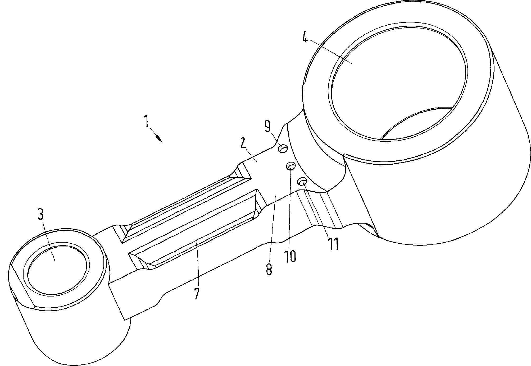
In
Die
Pleuelstange
Bei
diesem Ausführungsbeispiel
sind die Gefügeveränderungen
Die
Gefügeveränderungen
Die
Gefügeveränderungen
In
Bevorzugterweise ist die Pleuelstangenanordnung aus einem unlegierten Sintereisen hergestellt, das ein ferritisches Gefüge mit Fe3O4 aufweist. Die Härte sollte gleich oder höher als 100 kp/mm2 sein. Die Dichte nach der Dampfbehandlung sollte gleich oder größer als 6,8 g/cm3 betragen. Das Material darf keinen sichtbaren Schmutz aufweisen und sollte möglichst wenig reflektieren.Preferably, the connecting rod assembly is made of a non-alloyed sintered iron having a ferritic structure with Fe 3 O 4 . The hardness should be equal to or higher than 100 kgf / mm 2 . The density after steaming should be equal to or greater than 6.8 g / cm 3 . The material must not show any visible dirt and should reflect as little as possible.
In
In
Es ist auch denkbar, das Einbringen des kontrollierten Energieeintrags beispielsweise durch einen Laser in die Pleuelstangenanordnung erst dann einzubringen, wenn die Pleuelstangenanordnung bereits mit einer Kurbelwelle und einem Kolben verbunden ist oder sogar innerhalb des Kältemittelkompressors montiert ist. Die Anpassung der Pleuelstangenanordnung erfolgt dann nicht in erster Linie dahingehend, dass zwischen Pleuelauge und Kurbelauge eine möglichst hohe Parallelität ist, sondern so, dass zwischen Kurbelwelle und Kolben eine möglichst reibungsarme Kraftübertragung erfolgt. Die Kalibrierung der Pleuelstangenanordnung kann auch innerhalb einer Fertigungsstraße, in der der Kompressor gefertigt wird, durchgeführt werden.It is also conceivable to introduce the introduction of the controlled energy input, for example by a laser in the connecting rod assembly only when the connecting rod assembly is already connected to a crankshaft and a piston or even mounted within the refrigerant compressor. The adjustment of the connecting rod assembly is then not primarily singe Hend that between connecting rod and crank eye as high a parallelism, but so that between the crankshaft and piston as low as possible power transmission takes place. The calibration of the connecting rod assembly can also be performed within a production line in which the compressor is manufactured.
Insgesamt ist es durch die Erfindung möglich, den Wirkungsgrad eines Kältemittelkompressors zu verbessern, wobei gleichzeitig die Reibung verringert und die Lebensdauer erhöht wird. Dabei ist die Herstellung der Pleuelstangenanordnung sehr genau und relativ günstig.All in all is it possible by the invention the efficiency of a refrigerant compressor improve, while reducing friction and life elevated becomes. The production of the connecting rod assembly is very exactly and relatively cheap.
Claims (9)
Priority Applications (4)
| Application Number | Priority Date | Filing Date | Title |
|---|---|---|---|
| DE102009005935A DE102009005935B4 (en) | 2009-01-23 | 2009-01-23 | A method of calibrating a connecting rod assembly and connecting rod assembly |
| RU2010101246/02A RU2438816C2 (en) | 2009-01-23 | 2010-01-19 | Method of gauging con rod assembly and con rod assembly |
| US12/691,233 US8596187B2 (en) | 2009-01-23 | 2010-01-21 | Method of calibrating a connecting rod arrangement and connecting rod arrangement |
| CN201010103693.9A CN101791641B (en) | 2009-01-23 | 2010-01-25 | Method of calibrating a connecting rod arrangement and connecting rod arrangement |
Applications Claiming Priority (1)
| Application Number | Priority Date | Filing Date | Title |
|---|---|---|---|
| DE102009005935A DE102009005935B4 (en) | 2009-01-23 | 2009-01-23 | A method of calibrating a connecting rod assembly and connecting rod assembly |
Publications (2)
| Publication Number | Publication Date |
|---|---|
| DE102009005935A1 DE102009005935A1 (en) | 2010-07-29 |
| DE102009005935B4 true DE102009005935B4 (en) | 2010-10-07 |
Family
ID=42282555
Family Applications (1)
| Application Number | Title | Priority Date | Filing Date |
|---|---|---|---|
| DE102009005935A Active DE102009005935B4 (en) | 2009-01-23 | 2009-01-23 | A method of calibrating a connecting rod assembly and connecting rod assembly |
Country Status (4)
| Country | Link |
|---|---|
| US (1) | US8596187B2 (en) |
| CN (1) | CN101791641B (en) |
| DE (1) | DE102009005935B4 (en) |
| RU (1) | RU2438816C2 (en) |
Families Citing this family (3)
| Publication number | Priority date | Publication date | Assignee | Title |
|---|---|---|---|---|
| CN103335013A (en) * | 2013-06-26 | 2013-10-02 | 苏州市吴中区欣鑫开关配件厂 | Connecting rod of connecting lever |
| JP7320365B2 (en) | 2019-03-28 | 2023-08-03 | Ntn株式会社 | Sintered metal connecting rod and manufacturing method thereof |
| CN217652875U (en) * | 2021-10-25 | 2022-10-25 | 思科普有限责任公司 | Packaged refrigerant compressors |
Citations (7)
| Publication number | Priority date | Publication date | Assignee | Title |
|---|---|---|---|---|
| DE671433C (en) * | 1936-02-08 | 1939-02-07 | Ludwig Hunger | Straightening device for connecting rods |
| DE951306C (en) * | 1952-12-09 | 1956-10-25 | Ludwig Reinheimer | Connecting rod straightening and bending device |
| DE1552854B2 (en) * | 1966-11-16 | 1973-12-06 | Aeg-Elotherm Gmbh, 5630 Remscheid | Device for warming elongated workpieces made of electrically conductive metallic materials. Asssä ·. KEG-Eto * & raiömhH, 563O Remscheid |
| DE3830028C1 (en) * | 1988-09-03 | 1989-12-28 | Bayerische Motoren Werke Ag, 8000 Muenchen, De | |
| EP1285705A2 (en) * | 2001-08-13 | 2003-02-26 | Alcan Technology & Management Ltd. | Method and device for the calibration of a hollow profile or hollow body |
| DE102006028617B3 (en) * | 2006-06-22 | 2008-02-21 | Danfoss Compressors Gmbh | Piston compressor e.g. refrigerant compressor, has connecting rod that is connected with crank eye via hinge arrangement that has connection geometrics, where one geometry is inserted into wall of receiving area of other connection geometry |
| DE112006001926T5 (en) * | 2005-07-22 | 2008-07-03 | Gkn Sinter Metals Inc., Germantown | Rounding and straightening of cylindrical parts by laser |
Family Cites Families (13)
| Publication number | Priority date | Publication date | Assignee | Title |
|---|---|---|---|---|
| US1368194A (en) * | 1919-07-07 | 1921-02-08 | Charles G Patmon | Device for babbitting, reaming, and straightening connecting-rods |
| DE888401C (en) | 1943-07-20 | 1953-08-31 | Administration Sequestre Des R | Process for straightening workpieces |
| DE1403961A1 (en) * | 1963-03-01 | 1968-12-12 | Bosch Gmbh Robert | Connecting rod for a piston engine |
| JPS6045247B2 (en) * | 1978-07-07 | 1985-10-08 | 住友金属工業株式会社 | Heat treatment method for steel product surfaces using high energy beams |
| SU804074A1 (en) * | 1979-01-10 | 1981-02-15 | Предприятие П/Я А-1857 | Method and apparatus for straightening thin-walled tubes |
| JPH0327886U (en) * | 1989-07-26 | 1991-03-20 | ||
| JPH08501255A (en) * | 1993-03-25 | 1996-02-13 | インスティテュート ポヅタウォウィック プロブレモウテクニキ | Bending method for metal objects |
| DE59710231D1 (en) | 1997-09-20 | 2003-07-10 | Inpro Innovations Gmbh | Process for geometry detection and tracking during the thermal processing of components using laser radiation |
| DE10218141A1 (en) | 2002-04-29 | 2003-11-13 | Stiefelmayer Gmbh & Co Kg C | Process for the laser heat treatment of workpieces |
| JP4532058B2 (en) * | 2002-08-26 | 2010-08-25 | 日本発條株式会社 | Correction method, correction device, and correction program |
| DE10311238A1 (en) | 2003-03-14 | 2004-10-07 | Festo Ag & Co. | Method of manufacturing a valve |
| RU2277131C9 (en) * | 2004-09-28 | 2006-11-27 | Федеральное государственное унитарное предприятие "Производственное объединение "Электрохимический завод" | Device for thermal shaping of single-corrugation bellows |
| CN201148959Y (en) * | 2007-12-27 | 2008-11-12 | 杭州钱江制冷集团有限公司 | Compressor connection lever |
-
2009
- 2009-01-23 DE DE102009005935A patent/DE102009005935B4/en active Active
-
2010
- 2010-01-19 RU RU2010101246/02A patent/RU2438816C2/en not_active IP Right Cessation
- 2010-01-21 US US12/691,233 patent/US8596187B2/en active Active
- 2010-01-25 CN CN201010103693.9A patent/CN101791641B/en active Active
Patent Citations (8)
| Publication number | Priority date | Publication date | Assignee | Title |
|---|---|---|---|---|
| DE671433C (en) * | 1936-02-08 | 1939-02-07 | Ludwig Hunger | Straightening device for connecting rods |
| DE951306C (en) * | 1952-12-09 | 1956-10-25 | Ludwig Reinheimer | Connecting rod straightening and bending device |
| DE1552854B2 (en) * | 1966-11-16 | 1973-12-06 | Aeg-Elotherm Gmbh, 5630 Remscheid | Device for warming elongated workpieces made of electrically conductive metallic materials. Asssä ·. KEG-Eto * & raiömhH, 563O Remscheid |
| DE3830028C1 (en) * | 1988-09-03 | 1989-12-28 | Bayerische Motoren Werke Ag, 8000 Muenchen, De | |
| EP1285705A2 (en) * | 2001-08-13 | 2003-02-26 | Alcan Technology & Management Ltd. | Method and device for the calibration of a hollow profile or hollow body |
| EP1285705A3 (en) | 2001-08-13 | 2003-11-19 | Alcan Technology & Management Ltd. | Method and device for the calibration of a hollow profile or hollow body |
| DE112006001926T5 (en) * | 2005-07-22 | 2008-07-03 | Gkn Sinter Metals Inc., Germantown | Rounding and straightening of cylindrical parts by laser |
| DE102006028617B3 (en) * | 2006-06-22 | 2008-02-21 | Danfoss Compressors Gmbh | Piston compressor e.g. refrigerant compressor, has connecting rod that is connected with crank eye via hinge arrangement that has connection geometrics, where one geometry is inserted into wall of receiving area of other connection geometry |
Also Published As
| Publication number | Publication date |
|---|---|
| CN101791641B (en) | 2013-07-24 |
| US8596187B2 (en) | 2013-12-03 |
| CN101791641A (en) | 2010-08-04 |
| RU2438816C2 (en) | 2012-01-10 |
| DE102009005935A1 (en) | 2010-07-29 |
| US20100236401A1 (en) | 2010-09-23 |
| RU2010101246A (en) | 2011-07-27 |
Similar Documents
| Publication | Publication Date | Title |
|---|---|---|
| DE112012007218B4 (en) | Shear test device for mechanical material testing | |
| DE102008061315A1 (en) | Suspension of a valve plate on a valve rod | |
| DE19716880A1 (en) | Method of making a ball joint | |
| DE10024990B4 (en) | Method and device for inductive hardening of crankshafts | |
| CH708455B1 (en) | Sliding element, semi-cylindrical sliding bearing with it and method of manufacturing a sliding element. | |
| DE102009005935B4 (en) | A method of calibrating a connecting rod assembly and connecting rod assembly | |
| DE60133463T2 (en) | METHOD FOR PRODUCING A HIGH-TIGHT STEEL TUBE | |
| DE102005021793B4 (en) | Method and system for hardening transition radii of a shaft | |
| DE19905038B4 (en) | Spine device, cross rolling device and method for producing cross-rolled, at least partially hollow body | |
| DE102009031719A1 (en) | A compacting tool and method of making such a tool | |
| DE4237521A1 (en) | Process for producing a built crankshaft for reciprocating piston machines and process crankshaft | |
| DE102017010860A1 (en) | Connecting device for the connection of a damping unit of a vehicle within a suspension of the vehicle | |
| EP3609649B1 (en) | Method for post-processing a crankshaft | |
| EP3513084A1 (en) | Ball pin | |
| EP2397709B1 (en) | Ball joint and method for mounting same | |
| EP3447439B1 (en) | Template for representing a geometric reference curve, and uses of such a template | |
| DE102008027648A1 (en) | jig | |
| WO2009092530A2 (en) | Compressor cylinder head and method for producing a compressor cylinder head | |
| DE19902706C1 (en) | Spherical bearing between two components, preferably for knitting machines | |
| WO2017220202A9 (en) | Method for manufacturing a piston rod unit and a hollow shaft | |
| DE10126438A1 (en) | Shift rail with a shift fork | |
| EP1839790B1 (en) | Method and device for fracture-splitting of connecting rods | |
| DE4222748A1 (en) | Crankshaft mfr. with shape restrictions for bearings - involves compressing flat shaft bar region between shaft bearings in second heat | |
| DE10057640B4 (en) | Fracture splitting notches | |
| DE102023101099A1 (en) | Gripping device for flexible profiles with rolling friction intermediate clamping |
Legal Events
| Date | Code | Title | Description |
|---|---|---|---|
| OP8 | Request for examination as to paragraph 44 patent law | ||
| 8364 | No opposition during term of opposition | ||
| 8327 | Change in the person/name/address of the patent owner |
Owner name: DANFOSS FLENSBURG GMBH, 24939 FLENSBURG, DE |
|
| R081 | Change of applicant/patentee |
Owner name: SECOP GMBH, DE Free format text: FORMER OWNER: DANFOSS COMPRESSORS GMBH, 24939 FLENSBURG, DE Effective date: 20110310 |
|
| R082 | Change of representative |
Representative=s name: PATENTANWAELTE KNOBLAUCH UND KNOBLAUCH, DE Representative=s name: PATENTANWAELTE KNOBLAUCH UND KNOBLAUCH, 60322 FRAN |
|
| R081 | Change of applicant/patentee |
Owner name: SECOP GMBH, DE Free format text: FORMER OWNER: DANFOSS HOUSEHOLD COMPRESSORS GMBH, 24939 FLENSBURG, DE Effective date: 20120209 Owner name: SECOP GMBH, DE Free format text: FORMER OWNER: DANFOSS FLENSBURG GMBH, 24939 FLENSBURG, DE Effective date: 20111227 |
|
| R082 | Change of representative |
Representative=s name: PATENTANWAELTE KNOBLAUCH UND KNOBLAUCH, DE Effective date: 20120209 Representative=s name: PATENTANWAELTE KNOBLAUCH UND KNOBLAUCH, DE Effective date: 20111227 |
|
| R082 | Change of representative |
Representative=s name: KEIL & SCHAAFHAUSEN PATENTANWAELTE PARTGMBB, DE Representative=s name: KEIL & SCHAAFHAUSEN PATENT- UND RECHTSANWAELTE, DE |