DE102008012144B4 - Holding fitting and floor covering - Google Patents
Holding fitting and floor covering Download PDFInfo
- Publication number
- DE102008012144B4 DE102008012144B4 DE102008012144A DE102008012144A DE102008012144B4 DE 102008012144 B4 DE102008012144 B4 DE 102008012144B4 DE 102008012144 A DE102008012144 A DE 102008012144A DE 102008012144 A DE102008012144 A DE 102008012144A DE 102008012144 B4 DE102008012144 B4 DE 102008012144B4
- Authority
- DE
- Germany
- Prior art keywords
- fastening device
- plate
- claw
- support
- claws
- Prior art date
- Legal status (The legal status is an assumption and is not a legal conclusion. Google has not performed a legal analysis and makes no representation as to the accuracy of the status listed.)
- Active
Links
- 210000000078 claw Anatomy 0.000 claims abstract description 99
- 239000000758 substrate Substances 0.000 claims abstract description 9
- 230000037431 insertion Effects 0.000 claims description 18
- 238000003780 insertion Methods 0.000 claims description 18
- 238000009408 flooring Methods 0.000 claims description 10
- 238000004132 cross linking Methods 0.000 claims description 5
- 230000003014 reinforcing effect Effects 0.000 claims description 3
- 238000004519 manufacturing process Methods 0.000 claims description 2
- 238000003825 pressing Methods 0.000 claims description 2
- 230000002787 reinforcement Effects 0.000 claims description 2
- 230000003068 static effect Effects 0.000 claims 1
- 210000002414 leg Anatomy 0.000 description 23
- XLYOFNOQVPJJNP-UHFFFAOYSA-N water Substances O XLYOFNOQVPJJNP-UHFFFAOYSA-N 0.000 description 7
- 238000003801 milling Methods 0.000 description 5
- 239000000969 carrier Substances 0.000 description 4
- 230000015572 biosynthetic process Effects 0.000 description 3
- 239000000463 material Substances 0.000 description 3
- 239000002023 wood Substances 0.000 description 3
- 241000587161 Gomphocarpus Species 0.000 description 2
- 244000023431 Proboscidea parviflora Species 0.000 description 2
- 235000019096 Proboscidea parviflora Nutrition 0.000 description 2
- 239000002184 metal Substances 0.000 description 2
- 230000000149 penetrating effect Effects 0.000 description 2
- 229910001220 stainless steel Inorganic materials 0.000 description 2
- 239000010935 stainless steel Substances 0.000 description 2
- 210000000689 upper leg Anatomy 0.000 description 2
- 238000009825 accumulation Methods 0.000 description 1
- 230000035508 accumulation Effects 0.000 description 1
- 230000009286 beneficial effect Effects 0.000 description 1
- 238000005260 corrosion Methods 0.000 description 1
- 230000007797 corrosion Effects 0.000 description 1
- 230000001419 dependent effect Effects 0.000 description 1
- 150000002148 esters Chemical class 0.000 description 1
- 230000003287 optical effect Effects 0.000 description 1
- 238000004080 punching Methods 0.000 description 1
- 239000007787 solid Substances 0.000 description 1
- 125000006850 spacer group Chemical group 0.000 description 1
- 239000000725 suspension Substances 0.000 description 1
Classifications
-
- E—FIXED CONSTRUCTIONS
- E04—BUILDING
- E04F—FINISHING WORK ON BUILDINGS, e.g. STAIRS, FLOORS
- E04F15/00—Flooring
- E04F15/02—Flooring or floor layers composed of a number of similar elements
- E04F15/04—Flooring or floor layers composed of a number of similar elements only of wood or with a top layer of wood, e.g. with wooden or metal connecting members
-
- E—FIXED CONSTRUCTIONS
- E04—BUILDING
- E04F—FINISHING WORK ON BUILDINGS, e.g. STAIRS, FLOORS
- E04F15/00—Flooring
- E04F15/02—Flooring or floor layers composed of a number of similar elements
- E04F15/02044—Separate elements for fastening to an underlayer
-
- E—FIXED CONSTRUCTIONS
- E04—BUILDING
- E04F—FINISHING WORK ON BUILDINGS, e.g. STAIRS, FLOORS
- E04F15/00—Flooring
- E04F15/02—Flooring or floor layers composed of a number of similar elements
- E04F15/02177—Floor elements for use at a specific location
- E04F15/02183—Floor elements for use at a specific location for outdoor use, e.g. in decks, patios, terraces, verandas or the like
-
- E—FIXED CONSTRUCTIONS
- E04—BUILDING
- E04F—FINISHING WORK ON BUILDINGS, e.g. STAIRS, FLOORS
- E04F15/00—Flooring
- E04F15/02—Flooring or floor layers composed of a number of similar elements
- E04F15/02044—Separate elements for fastening to an underlayer
- E04F2015/0205—Separate elements for fastening to an underlayer with load-supporting elongated furring elements between the flooring elements and the underlayer
- E04F2015/02066—Separate elements for fastening to an underlayer with load-supporting elongated furring elements between the flooring elements and the underlayer with additional fastening elements between furring elements and flooring elements
- E04F2015/02077—Separate elements for fastening to an underlayer with load-supporting elongated furring elements between the flooring elements and the underlayer with additional fastening elements between furring elements and flooring elements the additional fastening elements located in-between two adjacent flooring elements
- E04F2015/02088—Engaging side holes preformed into the flooring elements
-
- E—FIXED CONSTRUCTIONS
- E04—BUILDING
- E04F—FINISHING WORK ON BUILDINGS, e.g. STAIRS, FLOORS
- E04F2201/00—Joining sheets or plates or panels
- E04F2201/05—Separate connectors or inserts, e.g. pegs, pins, keys or strips
-
- E—FIXED CONSTRUCTIONS
- E04—BUILDING
- E04F—FINISHING WORK ON BUILDINGS, e.g. STAIRS, FLOORS
- E04F2201/00—Joining sheets or plates or panels
- E04F2201/05—Separate connectors or inserts, e.g. pegs, pins, keys or strips
- E04F2201/0517—U- or C-shaped brackets and clamps
Landscapes
- Engineering & Computer Science (AREA)
- Architecture (AREA)
- Civil Engineering (AREA)
- Structural Engineering (AREA)
- Life Sciences & Earth Sciences (AREA)
- Wood Science & Technology (AREA)
- Floor Finish (AREA)
- Road Paving Structures (AREA)
- Connection Of Plates (AREA)
Abstract
Haltebeschlag zum Halten mindestens einer Bodenplatte (13a–13e), insbesondere einer Diele, auf einem Untergrund (35) zur Herstellung eines Bodenbelags (12) aus aneinander gereihten Bodenplatten (13a–13e), mit einer zum Auflegen auf einen Untergrund (35) vorgesehenen Trägerplatte (42a–42d), mit mindestens einer Befestigungseinrichtung (51) zur Befestigung auf dem Untergrund (35), und mit mindestens einer Kralle (40a–40d; 41a; 41c) zum Eingreifen in eine Ausnehmung (17) an einer Schmalseite (18) einer jeweiligen Bodenplatte (13a–13e), wobei die mindestens eine Kralle (40a–40d; 41a; 41c) einen von der Trägerplatte (42a–42d) abstehenden Stützabschnitt (44) und einen von dem Stützabschnitt (44) abstehenden, zu einer Oberseite (43) der Trägerplatte (42a–42d) zumindest abschnittsweise im wesentlichen parallel verlaufenden Eingriffabschnitt (45) zum Eingreifen in die Ausnehmung (17) der Bodenplatte (13a–13e) aufweist, dadurch gekennzeichnet, dass die Trägerplatte (42a–42d) Stützen (57) oder Stützbereiche (48) zum Abstützen auf dem Untergrund (35) und zur Herstellung eines Abstands (46) einer Plattenfläche (47) der Trägerplatte (42a–42d) zu dem Untergrund (35)...Holding fitting for holding at least one bottom plate (13a-13e), in particular a board, on a substrate (35) for producing a floor covering (12) of juxtaposed floor panels (13a-13e), provided with a for laying on a substrate (35) Support plate (42a-42d), with at least one fastening means (51) for attachment to the substrate (35), and at least one claw (40a-40d; 41a; 41c) for engaging in a recess (17) on a narrow side (18 ) of a respective bottom plate (13a-13e), wherein the at least one claw (40a-40d; 41a; 41c) projects from the support plate (42a-42d) projecting support portion (44) and one of the support portion (44), to a Having upper side (43) of the support plate (42a-42d) at least partially substantially parallel engagement portion (45) for engaging in the recess (17) of the bottom plate (13a-13e), characterized in that the carrier plate (42a 42d) supports (57) or supporting portions (48) (for support on the ground (35) and for producing a spacing (46) of a plate surface 47) of the support plate (42a-42d) to the substrate (35) ...
Description
Die Erfindung betrifft einen Haltebeschlag zum Halten mindestens einer Bodenplatte, insbesondere einer Diele, auf einem Untergrund zur Herstellung eines Bodenbelags aus aneinander gereihten Bodenplatten gemäß dem Oberbegriff des Anspruchs 1. Die Erfindung betrifft ferner einen Bodenbelag.The The invention relates to a retaining fitting for holding at least one Base plate, in particular a floorboard, on a substrate for Production of a floor covering of juxtaposed floor panels according to the generic term of claim 1. The invention further relates to a floor covering.
Zum Befestigen von Bodenplatten, z. B. Bodendielen, werden üblicherweise Schrauben oder Nägel verwendet, die durch die jeweiligen Bodenplatten genagelt oder geschraubt werden. Somit sieht man die Nagelköpfe oder Schraubenköpfe an der Oberseite der Bodenplatten, was optisch nicht ansprechend ist.To the Attaching floor panels, z. B. floorboards are usually Screws or nails used, nailed or screwed through the respective floor panels become. Thus you can see the nail heads or screw heads on the top the floor panels, which is not visually appealing.
Ein
Haltebeschlag gemäß dem Oberbegriff des
Anspruches 1 ist beispielsweise aus
Weitere
Haltebeschläge
dieser Art sind beispielsweise aus den Gebrauchsmustern
Weiterhin ist es im Außenbereich problematisch, wenn die in der Regel aus Holz bestehenden Bodenplatten unmittelbar auf den Untergrund geschraubt werden und sich unterhalb der Dielen und/oder in den Schraubenlöchern Wasser sammelt. Das führt langfristig zur Verrottung des Holzes.Farther it is outdoors problematic if the usually wooden existing floor panels be screwed directly to the ground and below the planks and / or in the screw holes collects water. That leads in the long run for rotting the wood.
Es ist daher die Aufgabe der vorliegenden Erfindung, eine optisch ansprechende, dauerhafte Befestigung für Bodenplatten, insbesondere Bodendielen für Terrassenbeläge und dergleichen, und einen damit hergestellten Bodenbelag bereit zu stellen.It It is therefore the object of the present invention to provide a visually appealing, permanent attachment for Floor panels, in particular floorboards for terrace coverings and the like, and to provide a flooring produced therewith.
Zur Lösung der Aufgabe ist ein Haltebeschlag gemäß der technischen Lehre des Anspruchs 1 vorgesehen. Zur Lösung der Aufgabe ist ferner ein Bodenbelag gemäß der technischen Lehre des Anspruchs 23 vorgesehen.to solution the task is a mounting bracket according to the technical teaching of Claim 1 provided. To the solution The object is also a floor covering according to the technical teaching of Claim 23 is provided.
Ein Grundgedanke der Erfindung ist, dass Schmalseiten der Bodenplatten zu deren Befestigung genutzt werden. Die runde oder vorzugsweise langlochartige Ausnehmung an der Bodenplatte kann von der Seite her in den Haltebeschlag eingeführt werden oder der Haltebeschlag von der Seite her in die Bodenplatte, was die Montage vereinfacht. Die Ausnehmung, beispielsweise eine Ausfräsung oder Bohrung, ist im mechanisch unbeanspruchten Seitenbereich, das heißt an der Schmalseite der Bodenplatte, angeordnet, wo sie in der Regel nicht sichtbar ist. Dadurch ist die Befestigung der Bodenplatten optisch vorteilhaft und zudem dauerhaft belastbar.One The basic idea of the invention is that narrow sides of the floor panels be used for their attachment. The round or preferably slot-like Recess on the bottom plate can from the side into the mounting bracket be introduced or the mounting bracket from the side into the bottom plate, what simplifies assembly. The recess, for example a cutout or hole, is in the mechanically unclaimed side area, that is on the Narrow side of the bottom plate, arranged where it usually does not is visible. As a result, the attachment of the floor panels is optical advantageous and also durable.
Der Haltebeschlag ist vorzugsweise aus Metall. Beispielsweise ist er als ein Stanzbiegeteil ausgeführt. Zur Korrosionsfestigkeit kann vorgesehen sein, dass der Haltebeschlag verzinkt ist oder aus einem Edelstahlmaterial besteht. Ferner ist es prinzipiell auch möglich, den Haltebeschlag zumindest teilweise aus Kunststoff zu fertigen.Of the Holding fitting is preferably made of metal. For example, he is executed as a stamped and bent part. For corrosion resistance can be provided that the retaining fitting is galvanized or made of a stainless steel material. Further is it is also possible in principle to make the retaining fitting at least partially made of plastic.
Die Trägerplatte hat Stützen oder Stützbereiche zum Abstützen auf dem Untergrund, so dass die Trägeplatte nur im Bereich der Stützen oder Stützbereiche mit dem Untergrund in Kontakt ist, während eine Plattenfläche der Trägerplatte, beispielsweise eine Plattenfläche in einem Mittenbereich der Trägerplatte, vom Untergrund beabstandet ist.The support plate has supports or support areas for supporting on the ground, so that the support plate only in the area of Support or support areas is in contact with the ground, while a plate surface of the Support plate for example, a plate surface in a middle region of the carrier plate, spaced from the ground.
Dies verhindert die Bildung von Wassernestern im Bereich des Haltebeschlages. Dadurch wird der Untergrund, der vorzugsweise aus quer zu den Bodenplatten verlaufenden Trägerleisten, Kanthölzern, Trägerbalken oder dergleichen, besteht, nicht durch stehendes Wasser belastet.This prevents the formation of water nests in the area of the retaining fitting. As a result, the substrate, preferably from across the floor panels extending carrier bars, Squared timber, beams or the like, is not burdened by stagnant water.
Die Befestigungseinrichtung ist zweckmäßigerweise an der Plattenfläche angeordnet, die aufgrund der Stützen oder Stützbereiche im montierten Zustand des Haltebeschlages von dem Untergrund beabstandet ist.The Fastening device is expediently arranged on the plate surface, because of the supports or support areas spaced in the assembled state of the retaining fitting from the ground is.
Die Stützen können beispielsweise durch Stützfüße gebildet sein. Besonders bevorzugt ist, wenn die Stützen durch Randabschnitte der Trägerplatte gebildet sind, die an einer von der mindestens einen Kralle entgegengesetzten Seite der Trägerplatte von dieser abstehen. Beispielsweise sind die Randabschnitte umgekantete und/oder umgefalzte Abschnitte der Trägerplatte.The Support can formed for example by support feet be. It is particularly preferred if the supports by edge sections of support plate are formed, which at one of the at least one claw opposite Side of the carrier plate stand out from this. For example, the edge portions are folded over and / or folded portions of the carrier plate.
Die Trägerplatte stellt zweckmäßigerweise einen Auflagebereich zum Auflegen der Bodenplatte(n) bereit, welche die mindestens eine Kralle oder die Krallenanordnung hält. Ansonsten wäre es auch denkbar, dass die Bodenplatte neben dem Haltebeschlag direkt auf dem Untergrund zu liegen kommt.The support plate is expediently one Supporting area for laying the bottom plate (s) ready, which the holds at least one claw or the claw assembly. Otherwise would it be Also conceivable that the bottom plate next to the mounting bracket directly to lie on the ground.
Die Befestigungseinrichtung umfasst zweckmäßigerweise eine Durchtrittsöffnung für einen Befestigungsbolzen, z. B. eine Schraube, einen Nagel oder dergleichen. Es versteht sich, dass z. B. an der Trägerplatte ein nagelartiger Vorsprung vorgesehen sein kann, der in einer Funktion als Befestigungseinrichtung in den Untergrund eindringt und den Haltebeschlag am Untergrund hält.The Fastening device expediently comprises a passage opening for a Fixing bolts, z. As a screw, a nail or the like. It is understood that z. B. on the carrier plate a nail-like Projection can be provided in a function as a fastening device penetrates into the ground and the mounting bracket on the ground holds.
Im Bereich der Durchtrittsöffnung ist zweckmäßigerweise eine Stütze oder ein Stützbereich zum Abstützen auf dem Untergrund vorgesehen. Somit ist ein Abstand zwischen der Plattenfläche, an der die Befestigungseinrichtung angeordnet ist, und dem Untergrund gewährleistet. Eine die Durchtrittsöffnung durchdringende Schraube oder ein Nagel zieht die Plattenfläche nicht in Richtung des Untergrundes, weil die Plattenfläche durch die Stütze oder den Stützbereich gestützt ist. Beispielsweise bildet ein Wandabschnitt im Bereich der Durchtrittsöffnung die Stütze. Vorteilhaft ist, wenn der Wandabschnitt trichterförmig oder senklochartig ist, um einen Schrauben- oder Nagelkopf aufzunehmen, der die Durchtrittsöffnung durchdringt.In the region of the passage opening, a support or a supporting area for supporting on the ground is expediently provided. Thus, a distance between the plate surface, on which the fastening device is arranged, and the ground is ensured. One the passage opening penetrating screw or a nail does not pull the plate surface in the direction of the ground, because the plate surface is supported by the support or the support area. For example, forms a wall portion in the region of the passage opening the support. It is advantageous if the wall portion is funnel-shaped or vertical hole-like, to receive a screw or nail head, which penetrates the passage opening.
An einem freien Ende der mindestens einen Kralle ist zweckmäßigerweise eine Einführschräge zum Einführen in die Ausnehmung der Bodenplatte angeordnet. Eine Einführschräge kann an einer von der Trägerplatte abgewandten Außenseite des freien Endes und/oder – besonders bevorzugt – an einer der Trägeplatte zugewandten Innenseite der mindestens einen Kralle vorgesehen sein. Auch an Querseiten des freien Endes kann mindestens eine Einführschräge vorgesehen sein. Beispielsweise wird eine Einführschräge durch einen Öffnungsbereich der Kralle erweiternden vorderen Abschnitt des Eingriffabschnittes gebildet. Mit Hilfe einer oder mehrerer Einführschrägen an der Kralle wird das Einführen in die Ausnehmung an der Schmalseite der Bodenplatte vereinfacht.At a free end of the at least one claw is expediently an insertion bevel for insertion into arranged the recess of the bottom plate. An insertion bevel can at one of the carrier plate opposite outside the free end and / or - especially preferred - on one of the support plate facing the inside of the at least one claw be provided. Also at transverse sides of the free end can be provided at least one insertion bevel be. For example, an insertion bevel through an opening area the claw expanding front portion of the engaging portion educated. With the help of one or more chamfers on the claw is the Introduce simplified in the recess on the narrow side of the bottom plate.
Der Bildung von Wassernestern oder Feuchtigkeit wirkt auch vorteilhaft entgegen, wenn eine der Trägerplatte zugewandte Innenseite der mindestens einen Kralle eine verhältnismäßig kleine, z. B. linienförmige oder punktförmige, Kontaktfläche zum Kontakt mit einer Innenwand der Ausnehmung der Bodenplatte aufweist. Es versteht sich, dass auch beispielsweise mehrere punktförmige Kontaktflächen diese Funktion erfüllen.Of the Formation of water esters or moisture also works beneficial contrary, if one of the carrier plate facing inside of the at least one claw a relatively small, z. B. linear or punctiform, contact area for contact with an inner wall of the recess of the bottom plate. It is understood that, for example, several punctiform contact surfaces this Fulfill function.
Die mindestens eine Kralle ist zweckmäßigerweise im Sinne eines Andrückens der Bodenplatte in Richtung der Trägerplatte federnd. Durch diese Elastizität ist gewährleistet, dass die Bodenplatte einerseits am Untergrund gehalten wird, andererseits aber Spiel vorhanden ist, beispielsweise bei Ausdehnung eines Holzmaterials oder dergleichen.The At least one claw is expediently in the sense of pressing the Base plate in the direction of the carrier plate springy. Due to this elasticity is guaranteed that the bottom plate is held on the one hand on the ground, on the other hand Game is present, for example, in expansion of a wood material or similar.
Die mindestens eine Kralle bildet vorteilhaft einen Bestandteil einer Klammer, die einen dem Eingriffabschnitt gegenüberliegenden Klammerschenkel aufweist. Die Klammer ist sozusagen U-förmig, wobei sich die beiden Klammerschenkel, von denen eine der Eingriffabschnitt der Kralle ist, nicht unbedingt gegenüberliegen müssen. Beispielsweise kann der Klammerschenkel durch die Trägerplatte bereitgestellt werden. Der Klammerschenkel kann z. B. seitlich neben dem Eingriffabschnitt angeordnet sein. Vorteilhaft wird der Klammerschenkel durch einen Stützbereich der Trägerplatte zum Abstützen derselben auf dem Untergrund gebildet. Dies ist beispielsweise dann gegeben, wenn die Klammer an einem Randbereich des Haltebeschlags angeordnet ist. Es ist aber auch möglich, dass der Klammerschenkel durch andere Bereiche der Trägerplatte gebildet ist, beispielsweise einen Auflagebereich zum Auflegen der durch die mindestens eine Klammer gehaltenen Bodenplatte.The At least one claw advantageously forms part of a Clamp having a clip leg opposite the engagement portion. The clamp is U-shaped, so to speak, wherein the two clip legs, one of which engaging portion the claw is not necessarily opposite. For example, the staple leg through the carrier plate to be provided. The staple leg can z. B. laterally next to be arranged the engagement portion. Advantageously, the staple leg through a support area the carrier plate for supporting the same formed on the ground. This is for example then given when the bracket is at an edge area of the retaining bracket is arranged. But it is also possible that the staple leg through other areas of the carrier plate is formed, for example, a support area for placing the by the at least one bracket held bottom plate.
Es versteht sich, dass der erfindungsgemäße Haltebeschlag eine oder mehrere Krallen aufweisen kann. Mehrere Krallen bilden einen Krallenanordnung. Dabei sind verschiedene der nachfolgenden erläuterten Konfigurationen – einzeln oder auch in Kombination miteinander – möglich.It is understood that the holding fitting according to the invention one or may have multiple claws. Several claws form a claw arrangement. Here are several of the following explained configurations - individually or in combination with each other - possible.
Mehrere Krallen können beispielsweise zur Längs- oder Querverkettung von Bodenplatten vorgesehen sein, die im Bereich des Haltebeschlags mit ihren Längsschmalseiten oder Querschmalseiten aneinander stoßen.Several Claws can for example, for longitudinal or cross-linking of floor slabs to be provided in the area the retaining fitting with its longitudinal narrow sides or transverse narrow sides abut each other.
Beispielsweise kann ein erfindungsgemäßer Haltebeschlag zwei an einander entgegengesetzten Seiten offene Krallen zum Eingriff in Ausnehmungen an mit ihren Längsschmalseiten nebeneinanderliegenden Bodenplatten aufweisen.For example can an inventive retaining fitting two on opposite sides open claws for engagement in recesses on with their longitudinal narrow sides have adjacent floor panels.
Die Krallen sind vorteilhaft in einer quer zu einer Einsteckrichtung der Krallen in die jeweilige Bodenplatten-Ausnehmung verlaufenden Reihenrichtung nebeneinander angeordnet. Die Stützabschnitte der mindestens zwei Krallen fluchten zweckmäßigerweise bezüglich dieser Reihenrichtung im Wesentlichen miteinander. Beispielsweise sind die Stützabschnitte in dieser Reihenrichtung hintereinander angeordnet. Die Reihenrichtung ist diejenige Richtung, die zu einer Längsrichtung der nebeneinanderliegenden Bodenplatte parallel verläuft. Durch die vorgenannte Maßnahme liegen die beiden Bodenplatten eng beieinander. Der Abstand zwischen den Bodenplatten entspricht dann etwa einer Querbreite der Stützabschnitte, sofern die jeweiligen Krallen ausreichend tief in die Ausnehmungen der Bodenplatten eingreifen können.The Claws are advantageous in a direction transverse to a plug the claws in the respective bottom plate recess extending Row direction arranged side by side. The support sections of at least two claws are appropriately aligned in terms of this row direction substantially with each other. For example are the support sections arranged one behind the other in this row direction. The row direction is the direction leading to a longitudinal direction of the adjacent ones Floor plate runs parallel. By the aforementioned measure The two floor panels are close together. The distance between the bottom plates then corresponds approximately to a transverse width of the support sections, provided the respective claws deep enough in the recesses the floor plates can intervene.
Bei einem solchen Haltebeschlag kann es auch möglich sein, dass dieser nicht nur zwei Bodenplatten in Querrichtung verkettet, sondern zudem mindestens eine Bodenplatte in Längsrichtung, wobei beispielsweise drei Bodenplatten von dem Haltebeschlag gehalten werden.at Such a retaining fitting it may also be possible that this is not only two bottom plates concatenated in the transverse direction, but also at least a bottom plate in the longitudinal direction, For example, where three bottom plates held by the mounting bracket become.
Der Haltebeschlag kann zu der vorgenannten Längsverkettung beispielsweise zwei in einem Längsabstand zueinander angeordnete, zur gleichen Seite offene Krallen aufweisen. Die Krallen können z. B. in Ausnehmungen an zwei in Längsrichtung hintereinander angeordneten Bodenplatten vorgesehen sein. Es ist aber auch möglich, dass die Krallen in Ausnehmungen zweier im Bereich des Haltebeschlags aneinander gereihten Bodenplatten eingreifen. Durch die Krallen kann ein Abstand zwischen diesen Bodenplatten definiert sein. Eine später noch beschriebene, bevorzugte Variante der Erfindung sieht jedoch vor, dass zur Einstellung dieses Abstandes mindestens ein Distanzelement, beispielsweise ein Dorn oder dergleichen, vorgesehen ist.The retaining fitting may, for example, have two claws, which are arranged at a longitudinal distance from each other and open on the same side, for the aforementioned longitudinal linking. The claws can z. B. be provided in recesses on two longitudinally successively arranged floor panels. But it is also possible that the claws engage in recesses of two in the region of the retaining fitting lined up floor panels. Due to the claws can be a distance between be defined this floor panels. A preferred embodiment of the invention which will be described later, however, provides that at least one spacer element, for example a mandrel or the like, is provided for setting this distance.
Zwei oder mehr Krallen können auch dafür vorgesehen sein, in dieselbe Ausnehmung an der Schmalseite einer Bodenplatte einzugreifen. Dies Ausnehmung ist dann als Langloch ausgestaltet. Die Krallen haben einen Außen-Längsabstand, der im Wesentlichen einer Längsbreite der Ausnehmung entspricht. Da durch wird eine Längsfixierung der Bodenplatte erzielt. Die Außenseiten der zueinander beabstandeten Platten liegen an den jeweiligen Längsenden der Ausnehmung an.Two or more claws can also intended for it be, in the same recess on the narrow side of a bottom plate intervene. This recess is then designed as a slot. The claws have an outer longitudinal distance, the substantially one longitudinal width the recess corresponds. Since by a longitudinal fixation of the bottom plate achieved. The outsides the spaced plates are at the respective longitudinal ends the recess.
Der Haltebeschlag hat zweckmäßigerweise einen oder mehrere Distanzanschläge, mit dem oder mit denen eine Distanz zwischen Bodenplatten einstellbar ist. Die Bodenplatten liegen im Bereich des Haltebeschlags nebeneinander, wenn sie mit dem Haltebeschlag montiert sind. Der Distanzanschlag kann eine Distanz in Längsrichtung oder Querrichtung der Bodenplatten festlegen. Mindestens eine der Bodenplatten wird dabei von dem Haltebeschlag gehalten. Es kann vorgesehen sein, dass der mindestens eine Distanzanschlag einen Abstand zwischen durch den Haltebeschlag verketteten Bodenplatten oder zwischen nicht durch den Haltebeschlag verketteten Bodenplatten einstellt.Of the Fastening has expediently one or more distance stops, with or with which a distance between floor plates adjustable is. The floor panels are adjacent to each other in the area of the retaining bracket, if they are mounted with the mounting bracket. The distance stop can a distance in the longitudinal direction or determine the transverse direction of the floor panels. At least one of Floor panels is held by the mounting bracket. It can be provided that the at least one distance stop a Distance between floor plates linked by the mounting bracket or between base plates not linked by the retaining fitting established.
Die Trägerplatte hat zweckmäßigerweise einen Befestigungsbereich, an dem die mindestens eine Befestigungseinrichtung und die mindestens eine Kralle angeordnet sind. Ferner ist bei der Trägerplatte ein Tragabschnitt mit einem Auflagebereich zum Auflegen der durch die mindestens eine Kralle gehaltenen Bodenplatte vorgesehen. Mit dem Befestigungsbereich kann die Trägerplatte an einem quer zu der Bodenplatte verlaufenden Träger befestigt sein. Der Tragabschnitt steht beispielsweise im montierten Zustand seitlich über den Träger vor.The support plate has expediently a fastening region on which the at least one fastening device and the at least one claw are arranged. Furthermore, at the support plate a support section with a support area for hanging by the at least one claw held bottom plate provided. With the mounting area, the support plate on a transverse to the bottom plate extending carrier be attached. The support section is, for example, in the mounted Condition laterally over the carrier in front.
Insbesondere bei dieser Konfiguration ist es vorteilhaft, wenn die Trägerplatte mindestens eine sie statisch verstärkede Trägerverstärkungseinrichtung aufweist. Diese kann beispielsweise durch einen umgekanteten oder umgefalzten Abschnitt gebildet werden. Vorzugsweise ist dies im Bereich des Tragabschnittes der Fall, so dass dieser auch dann, wenn er über den Träger seitlich vorsteht, eine Traglast, das heißt die Bodenplatte und eine gegebenenfalls auf der Bodenplatte auflastende Last, tragen kann.Especially In this configuration, it is advantageous if the carrier plate has at least one statically amplified carrier reinforcement device. This can, for example, by a folded or folded Section are formed. This is preferably in the range of Tragabschnittes the case, so this even if he over the carrier projecting laterally, a load, that is, the bottom plate and a possibly load on the bottom plate load bearing.
Der Haltebeschlag kann auch als ein Winkelbeschlag ausgestaltet sein. Von der Trägerplatte steht dann ein Halteschenkel (es können auch mehrere Halteschenkel vorgesehen sein), winkelig ab, so dass der Haltebeschlag an zueinander winkeligen Untergrundflächen des Untergrundes befestigbar ist. Dies ist beispielsweise am Ende eines Untergrund-Längsträgers oder -balkens vorteilhaft, wo der Winkel-Haltebeschlag angebracht werden kann. Der Haltebeschlag bildet dann eine Art Haltewinkel, der an den winkeligen Untergrundflächen, beispielsweise rechtwinkeligen Untergrundflächen, befestigbar ist.Of the Holding fitting can also be designed as an angle fitting. From the support plate is then a holding leg (it can also be provided a plurality of retaining legs), angled off, so that the mounting bracket on mutually angled ground surfaces of the Ground is fastened. This is for example at the end of a Underground side member or beam advantageous where the angle bracket are attached can. The mounting bracket then forms a kind of bracket that on the angular underground surfaces, For example, rectangular surface surfaces, is fastened.
Nachfolgend werden Ausführungsbeispiele der Erfindung anhand der Zeichnung erläutert. Es zeigen:following Be exemplary embodiments of Invention explained with reference to the drawing. Show it:
Bei den nachfolgenden Ausführungsbeispielen sind gleiche oder gleichartige Komponenten mit denselben Bezugszeichen versehen.at the following embodiments are the same or similar components with the same reference numerals Mistake.
Mit
den in den
Die
Bodenplatten
Mit
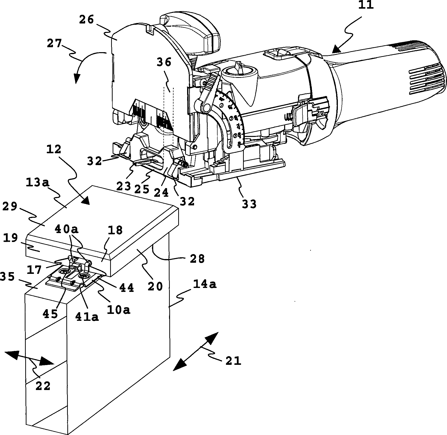
der Hand-Werkzeugmaschine
Zum
Fräsen
der Lang-Ausnehmungen
Die
Hand-Werkzeugmaschine
Der
Abstand
Zur
Einstellung eines Seitenabstandes
Die
Bodenfläche
Die
Haltebeschläge
Zur
Herstellung eines Abstandes
Die
Krallen
Neben
den durch das Ausstanzen der Krallen
Die
Durchtrittsöffnungen
Zwischen
den beiden Durchtrittsöffnungen
Bei
den Haltebeschlägen
Auch
bei den Halteschenkeln
Auch
im Bereich der Durchtrittsöffnungen
Die
Stützbereiche
Bei
den Haltebeschlägen
Ein
Einführen
der Krallen
Die
schmale Kontaktfläche
Mit
der Kontaktfläche
Die
Krallen
Die
Haltebeschläge
Die
Krallen
Der
Haltebeschlag
Eine
Längsfixierung
bezüglich
der Längsrichtung
Die
Haltebeschläge
Die
Tragabschnitte
Die
Befestigung des Bodenbelags
Zunächst werden
die Haltebeschläge
First, the retaining fittings
Dann
werden Krallen
Anschließend werden
die beiden kürzeren Bodenplatten
Dann
werden weitere Haltebeschläge
In
die Krallen
Zum
Abschluß wird
die als Querbrett dienende Bodenplatte
Der
Haltebeschlag
Am
Halteschenkel
Die
Halteeinrichtung
Die
Montage der stirnseitigen, ein Stellbrett bildenden Bodenplatte
Zunächst werden
die Haltebeschläge
First, the retaining fittings
Schließlich werden
die Haltebolzen
Dann
werden die Bolzenköpfe
Zum
Auffinden derjenigen Stellen, wo die Haltebolzen
Alternativ
und als optionale, vorteilhafte Maßnahme können auch Markiervorsprünge
Ferner
könnte
als Markiervorsprung beispielsweise auch der untere Randbereich
der Schlüssellochbohrung
Weiter
kann zum Auffinden der Schraub-Orte für die Haltebolzen
Zudem
ist es zweckmäßig, wenn
um den Halteabschnitt
Claims (23)
Priority Applications (2)
| Application Number | Priority Date | Filing Date | Title |
|---|---|---|---|
| DE102008012144A DE102008012144B4 (en) | 2008-03-01 | 2008-03-01 | Holding fitting and floor covering |
| EP09400004.9A EP2096233A3 (en) | 2008-03-01 | 2009-02-21 | Holder, floor covering and method for producing a floor covering |
Applications Claiming Priority (1)
| Application Number | Priority Date | Filing Date | Title |
|---|---|---|---|
| DE102008012144A DE102008012144B4 (en) | 2008-03-01 | 2008-03-01 | Holding fitting and floor covering |
Publications (2)
| Publication Number | Publication Date |
|---|---|
| DE102008012144A1 DE102008012144A1 (en) | 2009-09-03 |
| DE102008012144B4 true DE102008012144B4 (en) | 2010-03-11 |
Family
ID=40785343
Family Applications (1)
| Application Number | Title | Priority Date | Filing Date |
|---|---|---|---|
| DE102008012144A Active DE102008012144B4 (en) | 2008-03-01 | 2008-03-01 | Holding fitting and floor covering |
Country Status (2)
| Country | Link |
|---|---|
| EP (1) | EP2096233A3 (en) |
| DE (1) | DE102008012144B4 (en) |
Cited By (1)
| Publication number | Priority date | Publication date | Assignee | Title |
|---|---|---|---|---|
| DE102018005758A1 (en) * | 2018-07-20 | 2020-01-23 | Markus Rensberg | Mounting bracket for connecting adjacent decking boards |
Families Citing this family (12)
| Publication number | Priority date | Publication date | Assignee | Title |
|---|---|---|---|---|
| FR2958957B1 (en) * | 2010-04-15 | 2012-06-15 | Fribois | FIXING PIECE FOR FLOOR FLOORS |
| FR2963038B1 (en) * | 2010-07-21 | 2015-07-03 | Sas Michel Nordlinger | PERFECT MOUNTING CLIP |
| DE102011118508A1 (en) * | 2011-11-15 | 2013-05-16 | Stefan Ehrenreich | belt arrangement |
| DE102013001704A1 (en) * | 2013-02-01 | 2014-08-07 | Hüsler Silkwood GmbH | mounting profile |
| DE102014011946B3 (en) * | 2014-08-14 | 2015-11-12 | Stefan Ehrenreich | End plank holding device for a plank arrangement |
| AT515684B1 (en) * | 2014-10-14 | 2015-11-15 | Gaisbauer Günther | Facade system and a holding part for fixing two visible profiles |
| DE202017005643U1 (en) * | 2017-10-30 | 2019-01-31 | REHAU Gesellschaft m.b.H | fastening device |
| US10801537B2 (en) | 2018-01-05 | 2020-10-13 | Nova USA Wood Products, LLC | Resilient mounting clips, panel mount systems including the same, and associated methods |
| AT18230U1 (en) * | 2022-09-02 | 2024-06-15 | Reiter Klaus | Hallway |
| EP4361373A1 (en) * | 2022-10-28 | 2024-05-01 | Günther Gaisbauer | Terrace system and holder element for same |
| EP4361374B1 (en) * | 2022-10-28 | 2025-05-07 | Günther Gaisbauer | Terrace system and holder element for same |
| USD1115503S1 (en) | 2023-11-01 | 2026-03-03 | Nova USA Wood Products, LLC | Clip |
Citations (11)
| Publication number | Priority date | Publication date | Assignee | Title |
|---|---|---|---|---|
| GB403261A (en) * | 1933-03-31 | 1933-12-21 | Concrete Wood Floor Clip Compa | Improvements in and relating to fasteners for flooring, tiling, panelling and the like |
| DE29507264U1 (en) * | 1995-05-02 | 1995-09-21 | Gudermann, Adolf, 87480 Weitnau | Support and connecting profile spring rail with drainage function for the construction of wooden terraces, balconies, platforms etc. |
| DE29607962U1 (en) * | 1996-05-02 | 1996-07-18 | Rodriguez Lopez, Julio, Barcelona | Fastening device for wooden floors outdoors |
| EP1120515A1 (en) * | 2000-01-27 | 2001-08-01 | Triax N.V. | A combined set comprising a locking member and at least two building panels |
| FR2817891A1 (en) * | 2001-02-21 | 2002-06-14 | Alain Villafines | Mounting piece for parquet wooden strips comprises horizontal web in contact with backing strip upper face and strip underside and vertical web in contact with adjacent strip edges |
| US20030121226A1 (en) * | 2001-07-25 | 2003-07-03 | Manuel Bolduc | Method for installing wood flooring |
| DE202006006672U1 (en) * | 2005-05-24 | 2006-06-29 | Mayer, Margit | Fastening device for floor boards has slots between the boards to fasten them on a substructure for floor coverings on terraces, balconies or outer wall cladding |
| DE202006017973U1 (en) * | 2006-11-23 | 2007-04-26 | Göttlicher GmbH & Co. KG | Fastening unit for planks, has pin that is inserted into receiving hole in longitudinal side of planks, and butt strap provided below pin in base body, where strap lies against lower side of planks in mounted condition |
| AT502681B1 (en) * | 2005-11-28 | 2007-05-15 | Dietrich Anton Fuchs | DEVICE FOR FIXING PANELS TO A SUB-CONSTRUCTION |
| FR2893956A1 (en) * | 2005-11-29 | 2007-06-01 | Maderas Del Alto Urgel S A | Floor e.g. outer parquet, structure mounting system, has strips with end embedded in zone of one flange opposite to adjacent fixation element till one strip remains housed between fixation elements in parallel manner to floor or to base |
| AT502745B1 (en) * | 2005-10-31 | 2007-10-15 | Sebastian Fuchs | MOUNTING BOILERS |
Family Cites Families (5)
| Publication number | Priority date | Publication date | Assignee | Title |
|---|---|---|---|---|
| US6336300B1 (en) * | 1999-01-12 | 2002-01-08 | Fred M. Babucke | Device to divert water from deck |
| US6540432B2 (en) * | 2000-11-01 | 2003-04-01 | Andrew Albanese | Structural fastener system |
| JP4087825B2 (en) * | 2004-08-30 | 2008-05-21 | ハンディテクノ株式会社 | Deck structure |
| DE102004061437B4 (en) * | 2004-12-17 | 2007-05-03 | Dieter Reif | Mounting bracket for connecting wooden components |
| DE202008001033U1 (en) * | 2008-01-22 | 2008-03-27 | Rauschenberger, Udo | Bracket (terrace clip) |
-
2008
- 2008-03-01 DE DE102008012144A patent/DE102008012144B4/en active Active
-
2009
- 2009-02-21 EP EP09400004.9A patent/EP2096233A3/en not_active Withdrawn
Patent Citations (11)
| Publication number | Priority date | Publication date | Assignee | Title |
|---|---|---|---|---|
| GB403261A (en) * | 1933-03-31 | 1933-12-21 | Concrete Wood Floor Clip Compa | Improvements in and relating to fasteners for flooring, tiling, panelling and the like |
| DE29507264U1 (en) * | 1995-05-02 | 1995-09-21 | Gudermann, Adolf, 87480 Weitnau | Support and connecting profile spring rail with drainage function for the construction of wooden terraces, balconies, platforms etc. |
| DE29607962U1 (en) * | 1996-05-02 | 1996-07-18 | Rodriguez Lopez, Julio, Barcelona | Fastening device for wooden floors outdoors |
| EP1120515A1 (en) * | 2000-01-27 | 2001-08-01 | Triax N.V. | A combined set comprising a locking member and at least two building panels |
| FR2817891A1 (en) * | 2001-02-21 | 2002-06-14 | Alain Villafines | Mounting piece for parquet wooden strips comprises horizontal web in contact with backing strip upper face and strip underside and vertical web in contact with adjacent strip edges |
| US20030121226A1 (en) * | 2001-07-25 | 2003-07-03 | Manuel Bolduc | Method for installing wood flooring |
| DE202006006672U1 (en) * | 2005-05-24 | 2006-06-29 | Mayer, Margit | Fastening device for floor boards has slots between the boards to fasten them on a substructure for floor coverings on terraces, balconies or outer wall cladding |
| AT502745B1 (en) * | 2005-10-31 | 2007-10-15 | Sebastian Fuchs | MOUNTING BOILERS |
| AT502681B1 (en) * | 2005-11-28 | 2007-05-15 | Dietrich Anton Fuchs | DEVICE FOR FIXING PANELS TO A SUB-CONSTRUCTION |
| FR2893956A1 (en) * | 2005-11-29 | 2007-06-01 | Maderas Del Alto Urgel S A | Floor e.g. outer parquet, structure mounting system, has strips with end embedded in zone of one flange opposite to adjacent fixation element till one strip remains housed between fixation elements in parallel manner to floor or to base |
| DE202006017973U1 (en) * | 2006-11-23 | 2007-04-26 | Göttlicher GmbH & Co. KG | Fastening unit for planks, has pin that is inserted into receiving hole in longitudinal side of planks, and butt strap provided below pin in base body, where strap lies against lower side of planks in mounted condition |
Cited By (2)
| Publication number | Priority date | Publication date | Assignee | Title |
|---|---|---|---|---|
| DE102018005758A1 (en) * | 2018-07-20 | 2020-01-23 | Markus Rensberg | Mounting bracket for connecting adjacent decking boards |
| DE102018005758B4 (en) * | 2018-07-20 | 2021-03-11 | Markus Rensburg | Mounting bracket for connecting adjacent decking boards |
Also Published As
| Publication number | Publication date |
|---|---|
| EP2096233A2 (en) | 2009-09-02 |
| DE102008012144A1 (en) | 2009-09-03 |
| EP2096233A3 (en) | 2017-11-15 |
Similar Documents
| Publication | Publication Date | Title |
|---|---|---|
| DE102008012144B4 (en) | Holding fitting and floor covering | |
| DE3502959C2 (en) | Wedge for use on slatted substructures of wall cladding | |
| DE3438365C2 (en) | Profile rod for clamping plates, in particular glass plates for showcases, sales counters, trade fair furniture or the like. | |
| EP2063047A1 (en) | Profile rail system | |
| DE102009031825A1 (en) | Fastening clamp for e.g. connecting two adjacent floorings, has retaining profile holding flooring, and bearing section including fastening opening for fastening another flooring with screw from top through sole plate to substrate | |
| DE202011100302U1 (en) | Invisible fastening device (Thermofix) for the production of a surface made of climatically volume-resistant strips or boards, for indoor and outdoor use (eg terrace) | |
| EP1870529B1 (en) | Wall/cupboard assembly with a frame construction | |
| DE60312728T2 (en) | Kit with a parquet rod and a mounting bracket for this | |
| DE10107866A1 (en) | Wainscot cover strip is recessed on holding surface for holding element baseplate tongue at baseplate top and bottom edges. | |
| DE102009047415A1 (en) | Board arrangement e.g. gypsum plaster board arrangement, for drywall construction, has assembly aid element and board that are formed such that assembly aid element completely remains in wall, cover or cladding as lost component | |
| DE202019101409U1 (en) | Profile system for forming a sub-frame for receiving floor coverings and connecting element | |
| WO2009006926A1 (en) | 45° wall panel concept | |
| EP1790794A2 (en) | Device for fixing covering panels to a substructure | |
| CH700410B1 (en) | Facade construction. | |
| DE102016124988B4 (en) | Hardware and method for installing decking | |
| DE19903133C2 (en) | System for fastening paneling panels, such as panels, profiled boards, and tongue and groove boards in front of walls, ceilings or floors | |
| WO2013139446A2 (en) | Fastening clip for connecting components | |
| EP3296486B1 (en) | Building cladding with a fitting set for the joining of elongated cover elements | |
| AT507840B1 (en) | FACADE ELEMENT | |
| DE2757957C3 (en) | Overlapped wooden cladding made of sub-boards attached to a ceiling or wall and overlapping top boards | |
| DE102014011946B3 (en) | End plank holding device for a plank arrangement | |
| DE202008016278U1 (en) | Invisible fitting for the production of a wooden floor in the lath composite for the outside area (for example terrace) | |
| AT503243B1 (en) | PLINTH | |
| DE20112018U1 (en) | Double angle plate | |
| DE102014011947B3 (en) | End plank holding device for a plank arrangement |
Legal Events
| Date | Code | Title | Description |
|---|---|---|---|
| OP8 | Request for examination as to paragraph 44 patent law | ||
| 8364 | No opposition during term of opposition | ||
| R082 | Change of representative |
Representative=s name: PATENTANWAELTE MAGENBAUER & KOLLEGEN, DE |
|
| R081 | Change of applicant/patentee |
Owner name: FESTOOL GMBH, DE Free format text: FORMER OWNER: FESTOOL GMBH, 73240 WENDLINGEN, DE Effective date: 20121119 Owner name: FESTOOL GROUP GMBH & CO. KG, DE Free format text: FORMER OWNER: FESTOOL GMBH, 73240 WENDLINGEN, DE Effective date: 20121119 |
|
| R082 | Change of representative |
Representative=s name: PATENTANWAELTE BREGENZER UND REULE PARTNERSCHA, DE Effective date: 20121119 Representative=s name: BREGENZER, MICHAEL, DIPL.-ING., DE Effective date: 20121119 Representative=s name: PATENTANWAELTE MAGENBAUER & KOLLEGEN, DE Effective date: 20121119 |
|
| R082 | Change of representative |
Representative=s name: BREGENZER, MICHAEL, DIPL.-ING., DE |
|
| R081 | Change of applicant/patentee |
Owner name: FESTOOL GMBH, DE Free format text: FORMER OWNER: FESTOOL GROUP GMBH & CO. KG, 73240 WENDLINGEN, DE Effective date: 20140918 |
|
| R082 | Change of representative |
Representative=s name: PATENTANWAELTE BREGENZER UND REULE PARTNERSCHA, DE Effective date: 20140918 Representative=s name: BREGENZER, MICHAEL, DIPL.-ING., DE Effective date: 20140918 |
|
| R082 | Change of representative |
Representative=s name: PATENTANWAELTE BREGENZER UND REULE PARTNERSCHA, DE |