DE102007061011A1 - Electromotive auxiliary drive, for example windscreen wiper drive - Google Patents
Electromotive auxiliary drive, for example windscreen wiper drive Download PDFInfo
- Publication number
- DE102007061011A1 DE102007061011A1 DE102007061011A DE102007061011A DE102007061011A1 DE 102007061011 A1 DE102007061011 A1 DE 102007061011A1 DE 102007061011 A DE102007061011 A DE 102007061011A DE 102007061011 A DE102007061011 A DE 102007061011A DE 102007061011 A1 DE102007061011 A1 DE 102007061011A1
- Authority
- DE
- Germany
- Prior art keywords
- contact
- housing part
- auxiliary drive
- drive according
- housing
- Prior art date
- Legal status (The legal status is an assumption and is not a legal conclusion. Google has not performed a legal analysis and makes no representation as to the accuracy of the status listed.)
- Granted
Links
- 238000005304 joining Methods 0.000 claims abstract description 28
- 230000005540 biological transmission Effects 0.000 claims description 17
- 239000004033 plastic Substances 0.000 claims description 8
- 230000001154 acute effect Effects 0.000 claims description 5
- 239000007769 metal material Substances 0.000 claims description 5
- 238000005452 bending Methods 0.000 claims description 4
- 239000004020 conductor Substances 0.000 claims description 4
- 230000002093 peripheral effect Effects 0.000 description 5
- 238000001746 injection moulding Methods 0.000 description 4
- 239000000463 material Substances 0.000 description 4
- 230000013011 mating Effects 0.000 description 4
- 238000004804 winding Methods 0.000 description 4
- 238000013461 design Methods 0.000 description 2
- 238000004519 manufacturing process Methods 0.000 description 2
- 238000003825 pressing Methods 0.000 description 2
- BUHVIAUBTBOHAG-FOYDDCNASA-N (2r,3r,4s,5r)-2-[6-[[2-(3,5-dimethoxyphenyl)-2-(2-methylphenyl)ethyl]amino]purin-9-yl]-5-(hydroxymethyl)oxolane-3,4-diol Chemical compound COC1=CC(OC)=CC(C(CNC=2C=3N=CN(C=3N=CN=2)[C@H]2[C@@H]([C@H](O)[C@@H](CO)O2)O)C=2C(=CC=CC=2)C)=C1 BUHVIAUBTBOHAG-FOYDDCNASA-N 0.000 description 1
- 229920002943 EPDM rubber Polymers 0.000 description 1
- 241000237858 Gastropoda Species 0.000 description 1
- 230000000454 anti-cipatory effect Effects 0.000 description 1
- 238000011161 development Methods 0.000 description 1
- 230000018109 developmental process Effects 0.000 description 1
- 238000002347 injection Methods 0.000 description 1
- 239000007924 injection Substances 0.000 description 1
- 230000002045 lasting effect Effects 0.000 description 1
- 239000002184 metal Substances 0.000 description 1
- 238000000034 method Methods 0.000 description 1
- 238000012986 modification Methods 0.000 description 1
- 230000004048 modification Effects 0.000 description 1
- 239000002991 molded plastic Substances 0.000 description 1
- 238000012549 training Methods 0.000 description 1
Classifications
-
- B—PERFORMING OPERATIONS; TRANSPORTING
- B60—VEHICLES IN GENERAL
- B60S—SERVICING, CLEANING, REPAIRING, SUPPORTING, LIFTING, OR MANOEUVRING OF VEHICLES, NOT OTHERWISE PROVIDED FOR
- B60S1/00—Cleaning of vehicles
- B60S1/02—Cleaning windscreens, windows or optical devices
- B60S1/04—Wipers or the like, e.g. scrapers
- B60S1/06—Wipers or the like, e.g. scrapers characterised by the drive
- B60S1/16—Means for transmitting drive
- B60S1/166—Means for transmitting drive characterised by the combination of a motor-reduction unit and a mechanism for converting rotary into oscillatory movement
-
- H—ELECTRICITY
- H02—GENERATION; CONVERSION OR DISTRIBUTION OF ELECTRIC POWER
- H02K—DYNAMO-ELECTRIC MACHINES
- H02K11/00—Structural association of dynamo-electric machines with electric components or with devices for shielding, monitoring or protection
- H02K11/20—Structural association of dynamo-electric machines with electric components or with devices for shielding, monitoring or protection for measuring, monitoring, testing, protecting or switching
- H02K11/21—Devices for sensing speed or position, or actuated thereby
-
- H—ELECTRICITY
- H02—GENERATION; CONVERSION OR DISTRIBUTION OF ELECTRIC POWER
- H02K—DYNAMO-ELECTRIC MACHINES
- H02K5/00—Casings; Enclosures; Supports
- H02K5/04—Casings or enclosures characterised by the shape, form or construction thereof
- H02K5/22—Auxiliary parts of casings not covered by groups H02K5/06-H02K5/20, e.g. shaped to form connection boxes or terminal boxes
- H02K5/225—Terminal boxes or connection arrangements
-
- H—ELECTRICITY
- H02—GENERATION; CONVERSION OR DISTRIBUTION OF ELECTRIC POWER
- H02K—DYNAMO-ELECTRIC MACHINES
- H02K7/00—Arrangements for handling mechanical energy structurally associated with dynamo-electric machines, e.g. structural association with mechanical driving motors or auxiliary dynamo-electric machines
- H02K7/10—Structural association with clutches, brakes, gears, pulleys or mechanical starters
- H02K7/116—Structural association with clutches, brakes, gears, pulleys or mechanical starters with gears
- H02K7/1163—Structural association with clutches, brakes, gears, pulleys or mechanical starters with gears where at least two gears have non-parallel axes without having orbital motion
- H02K7/1166—Structural association with clutches, brakes, gears, pulleys or mechanical starters with gears where at least two gears have non-parallel axes without having orbital motion comprising worm and worm-wheel
-
- H—ELECTRICITY
- H01—ELECTRIC ELEMENTS
- H01R—ELECTRICALLY-CONDUCTIVE CONNECTIONS; STRUCTURAL ASSOCIATIONS OF A PLURALITY OF MUTUALLY-INSULATED ELECTRICAL CONNECTING ELEMENTS; COUPLING DEVICES; CURRENT COLLECTORS
- H01R13/00—Details of coupling devices of the kinds covered by groups H01R12/70 or H01R24/00 - H01R33/00
- H01R13/02—Contact members
- H01R13/04—Pins or blades for co-operation with sockets
- H01R13/05—Resilient pins or blades
-
- H—ELECTRICITY
- H01—ELECTRIC ELEMENTS
- H01R—ELECTRICALLY-CONDUCTIVE CONNECTIONS; STRUCTURAL ASSOCIATIONS OF A PLURALITY OF MUTUALLY-INSULATED ELECTRICAL CONNECTING ELEMENTS; COUPLING DEVICES; CURRENT COLLECTORS
- H01R4/00—Electrically-conductive connections between two or more conductive members in direct contact, i.e. touching one another; Means for effecting or maintaining such contact; Electrically-conductive connections having two or more spaced connecting locations for conductors and using contact members penetrating insulation
- H01R4/58—Electrically-conductive connections between two or more conductive members in direct contact, i.e. touching one another; Means for effecting or maintaining such contact; Electrically-conductive connections having two or more spaced connecting locations for conductors and using contact members penetrating insulation characterised by the form or material of the contacting members
- H01R4/64—Connections between or with conductive parts having primarily a non-electric function, e.g. frame, casing, rail
Landscapes
- Engineering & Computer Science (AREA)
- Power Engineering (AREA)
- Microelectronics & Electronic Packaging (AREA)
- Mechanical Engineering (AREA)
- Motor Or Generator Frames (AREA)
- Connection Of Motors, Electrical Generators, Mechanical Devices, And The Like (AREA)
Abstract
Elektromotorischer Hilfsantrieb, beispielsweise Scheibenwischerantrieb, mit wenigstens einem ersten Gehäuseteil und mit wenigstens einem durch Aufsetzen in einer Füge-Richtung an dem ersten Gehäuseteil befestigbaren zweiten Gehäuseteil sowie mit einer beim Fügen der Gehäuseteile hergestellten elektrischen Verbindung innerhalb des Gehäuses über einen wenigstens eine Kontaktfläche aufweisenden Kontaktbereich an dem ersten Gehäuseteil und über wenigstens einen gegen die Kontaktfläche anliegenden Kontakt oder Kontaktabschnitt am zweiten Gehäuseteil.Electromotive auxiliary drive, such as windshield wiper drive, with at least a first housing part and at least one attachable in a joining direction to the first housing part second housing part and with an electrical connection produced during the joining of the housing parts within the housing via a contact surface having at least one contact area the first housing part and via at least one voltage applied to the contact surface contact or contact portion on the second housing part.
Description
Die Erfindung bezieht sich auf einen eletromotorischen Hilfsantrieb gemäß Oberbegriff Patentanspruch 1.The The invention relates to an electromotive auxiliary drive according to the preamble of claim 1.
Elektromotorische
Hilfsantriebe für Fahrzeuge, insbesondere auch als Getriebemotoren,
beispielsweise Scheibenwischerantriebe, sind in unterschiedlichen
Ausführungen bekannt. Bekannt ist hierbei speziell auch,
zwischen zwei Gehäuseteilen, nämlich z. B. zwischen
einem Getriebegehäuse oder einem dort vorgesehenen Funktionselement
und einem Deckel des Getriebegehäuses eine elektrische Verbindung
vorzusehen, die aus einem über die Innenseite des Deckels
wegstehenden leistenartigen Kontakt und aus einem Kontaktbereich
oder Gegenkontakt besteht, der am Getriebegehäuse bzw.
an einem dortigen elektrischen Funktionselement derart vorgesehen
ist, dass beim Aufsetzen des Deckels auf das Gehäuse in
einer Fügerichtung die elektrische Verbindung des Kontakts
am Deckel mit dem Kontaktbereich im Getriebegehäuse hergestellt
wird (
Aufgabe der Erfindung ist es, einen elektromotorischen Hilfsantrieb aufzuzeigen, dessen Gehäuse, insbesondere Getriebegehäuse aus wenigstens einem ersten und wenigstens einem zweiten Gehäuseteil besteht und bei welchem zumindest ein elektrischer Kontakt oder Kontaktabschnitt, der am zweiten Gehäuseteil vorgesehen ist und mit einem elektrischen Gegenkontakt oder Kontaktbereich am ersten Gehäuseteil zusammenwirkt, hinterschnittfrei ausgebildet ist und dennoch eine zuverlässige und dauerhafte elektrische Verbindung über den Kontakt oder Kontaktabschnitt und den Kontaktbereich nach dem Fügen der Gehäuseteile gewährleistet ist. Zur Lösung dieser Aufgabe ist ein elektromotorischer Hilfsantrieb entsprechend dem Patentanspruch 1 ausgebildet.task the invention is to show an electric motor auxiliary drive, the housing, in particular gearbox at least one first and at least one second housing part exists and in which at least one electrical contact or Contact section provided on the second housing part is and with an electrical mating contact or contact area cooperates on the first housing part, undercut formed is and still a reliable and durable electric Connection via the contact or contact section and the Contact area after joining the housing parts is guaranteed. To solve this problem is an electric motor auxiliary drive according to the claim 1 formed.
Obwohl der wenigstens eine Kontakt oder Kontaktabschnitt am zweiten Gehäuseteil und der Kontaktbereich am ersten Gehäuseteil ohne Hinterschnitt ausgeführt sind, ist auch bei völlig unelastischen Gehäuseteilen und bei Herstellung des Kontaktes oder Kontaktabschnitts aus einem nur bedingt federnde Eigenschaften aufweisenden Werkstoff eine dauerhafte, zuverlässige Verbindung über den wenigstens einen Kontakt oder Kontaktabschnitts und den Kontaktbereich gewährleistet, und zwar allein durch das Fügen oder Verbinden der Gehäuseteile.Even though the at least one contact or contact portion on the second housing part and the contact area on the first housing part without undercut are executed, is also completely inelastic Housing parts and when producing the contact or contact section from a material having only limited elastic properties a permanent, reliable connection over the at least ensures a contact or contact section and the contact area, and solely by the joining or connecting the housing parts.
Durch die erfindungsgemäße Ausbildung kommt beim Verbinden der Gehäuseteile der zunächst völlig geradlinig ausgebildete und in dieser Form vom zweiten Gehäuseteil wegstehende Kontakt oder Kontaktabschnitt gegen die zugeordnete und als Schrägfläche ausgebildete Kontaktfläche des Kontaktbereiches zur Anlage. Hierbei wird der Kontakt oder Kontaktabschnitt beim weiteren Fügen der Gehäuseteile, d. h. z. B. beim weiteren Aufsetzen oder Aufschieben des zweiten Gehäuseteils, an der Schrägfläche gleitend zunehmend in einer Biegerichtung quer zu seiner Längsertreckung gebogen, so dass der Kontakt oder Kontaktabschnitt dann leicht federnd gegen die als Schrägfläche ausgebildete Kontaktfläche anliegt.By the training of the invention comes when connecting the housing parts of the first completely formed in a straight line and in this form from the second housing part wegstehende contact or contact section against the assigned and formed as an inclined surface contact surface the contact area to the system. Here, the contact or contact section when further joining the housing parts, d. H. z. B. during further placement or pushing on the second housing part, sliding on the inclined surface increasingly in one Bending direction bent transversely to its longitudinal extent, so that the contact or contact section then slightly resilient against the formed as an inclined surface contact surface is applied.
Bei einer bevorzugten Ausführungsform ist der Schrägfläche wenigstens ein Gegenlager zugeordnet, gegen welches der wenigstens eine Kontakt oder Kontaktabschnitt z. B. im Bereich seines freien Endes mit der der Schrägfläche abgewandte Seite entgegen der Biegerichtung zurückgedrückt oder zurückgebogen anliegt. Hierdurch wird auch bei einer nur bedingt federnden Eigenschaft des Kontaktes oder Kontaktabschnitts die angestrebte sichere und dauerhafte Kontaktierung beim Fügen der Gehäuseteile zuverlässig gewährleistet.at a preferred embodiment is the inclined surface associated with at least one counter-bearing, against which the at least a contact or contact section z. B. in the region of its free end with the side facing away from the inclined surface opposite the bending direction pushed back or bent back is applied. As a result, even with a limited resilience property the contact or contact section the desired safe and lasting Contacting when joining the housing parts reliable guaranteed.
Der wenigstens eine an dem zweiten Gehäuseteil vorgesehene Kontakt bildet vorzugsweise zumindest zwei sich jeweils in Fügerichtung erstreckende und voneinander getrennte Kontaktabschnitte, denen dann am Kontaktbereich jeweils eine eigenständige Kontaktfläche bzw. Schrägfläche zugeordnet ist, und zwar in der Form, dass die Schrägflächen in Bezug auf die Fügerichtung entgegengesetzt geneigt sind und mit ihren Ebenen einen spitzen Winkel kleiner als 45° einschließen, der sich zu der dem zweiten Gehäuseteil abgewandten Seite hin öffnet. Jeder Schrägfläche ist wenigstens ein Gegenlager zugeordnet.Of the at least one provided on the second housing part Contact preferably forms at least two each in the joining direction extending and separate contact sections, which then at the contact area in each case an independent contact area or inclined surface is assigned, in the shape that the bevels in relation to the joining direction are inclined opposite and with their Planes include an acute angle less than 45 °, to the side facing away from the second housing part opens. Each bevel is at least associated with an abutment.
Bei einer bevorzugten Ausführungsform ist das zweite Gehäuseteil als Formteil als Kunststoff hergestellt, und zwar in der Weise, dass der wenigstens eine Kontakt oder Kontaktabschnitt von einem Abschnitt eines mit dem Kunststoff umspritzten Leiters aus Metall gebildet ist. Durch die hinterschnittfreie und gerade Form des beispielsweise leisten- oder laschenartigen Kontaktes oder Kontaktabschnitts ist die Entformbarkeit des zweiten Gehäuseteils aus dem Kunststoffspritzwerkzeug gewährleistet.at a preferred embodiment, the second housing part manufactured as a molded part as a plastic, in such a way that the at least one contact or contact portion of a section made of metal overmolded with the plastic conductor is. Due to the undercut-free and straight shape of the example strip or tab-like contact or contact portion is the mold release of the second housing part from the plastic injection mold guaranteed.
Das erste Gehäuseteil ist beispielsweise ein aus einem metallischen Werkzeug durch Spritzgießen hergestelltes Getriebegehäuse. Das zweite Gehäuseteil ist dann der das Getriebegehäuse verschließende Deckel. Die den Kontaktbereich bzw. die dortigen Kontaktflächen bildende wenigstens eine Schrägfläche ist dabei beispielsweise an einem einstückig mit dem Getriebegehäuse hergestellten Abschnitt, beispielsweise an einem Vorsprung gebildet, so dass sich über den wenigstens einen Kontakt oder Kontaktabschnitt am Gehäusedeckel und dem Kontaktbereich am Getriebegehäuse eine zuverlässige Masseverbindung zum Getriebegehäuse ergibt.The first housing part is, for example, a gear housing made of a metallic tool by injection molding. The second housing part is then the cover closing the transmission housing. The at least one inclined surface forming the contact region or the contact surfaces there is formed, for example, on a section produced in one piece with the transmission housing, for example on a projection, so that over at least one contact or Contact section on the housing cover and the contact area on the gear housing results in a reliable ground connection to the gear housing.
Weiterbildungen, Vorteile und Anwendungsmöglichkeiten der Erfindung ergeben sich auch aus der nachfolgenden Beschreibung von Ausführungsbeispielen und aus den Figuren. Dabei sind alle beschriebenen und/oder bildlich dargestellten Merkmale für sich oder in beliebiger Kombination grundsätzlich Gegenstand der Erfindung, unabhängig von ihrer Zusammenfassung in den Ansprüchen oder deren Rückbeziehung. Auch wird der Inhalt der Ansprüche zu einem Bestandteil der Beschreibung gemacht.Further developments, Advantages and applications of the invention result also from the following description of exemplary embodiments and from the figures. All are described and / or illustrated illustrated features alone or in any combination in principle subject of the invention, independent from their summary in the claims or their dependency. Also, the content of the claims becomes an integral part the description made.
Die Erfindung wird im Folgenden anhand der Figuren an einem Ausführungsbeispiel näher erläutert. Es zeigen:The Invention will be described below with reference to the figures of an embodiment explained in more detail. Show it:
In
den Figuren ist
Das
aus einem metallischen Material, beispielsweise unter Verwendung
einer geeigneten Spritzgusstechnik mit einem Gehäuseboden
Mit
In
der Verlängerung
Bei
der dargestellten Ausführungsform sind am Deckel
Der
Kontakt
Die
in den Figuren nur angedeuteten, insbesondere im Deckelboden
Die
beiden Kontakte
Über
den Kontakt
Die
Schrägflächen
Dem
unteren, dem Gehäuseboden
Der
beschriebene Kontaktbereich
Der
Kontakt
Unmittelbar
vor dem endgültigen Verbinden des Deckels
Durch
die in den Zentrieröffnungen geführten Zentrierzapfen
wird auch verhindert, dass der Deckel
Wie
die Figuren zeigen, bildet der Vorsprung
Die Erfindung wurde voranstehend an einem Ausführungsbeispiel beschrieben. Es versteht sich, dass zahlreiche Änderungen sowie Abwandlungen möglich sind, ohne das dadurch der der Erfindung zugrunde liegende Erfindungsgedanke verlassen wird.The The invention has been described in an embodiment described. It is understood that many changes As well as modifications are possible, without thereby the the Invention invention is abandoned.
- 11
- Hilfsantriebauxiliary drive
- 22
- Getriebetransmission
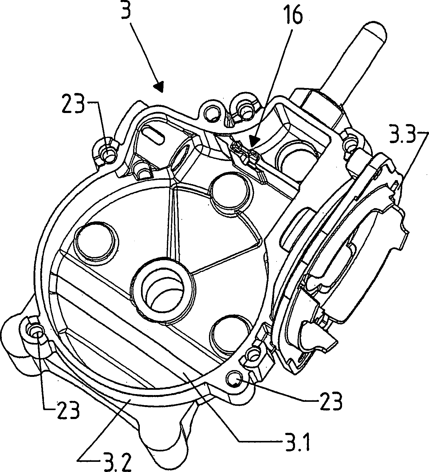
- 33
- Getriebegehäusegearbox
- 3.13.1
- Gehäusebodencaseback
- 3.23.2
- GehäuseumfangwandHousing peripheral wall
- 3.33.3
- Flanschflange
- 44
- Elektromotorelectric motor
- 4.14.1
- Motorgehäusemotor housing
- 4.24.2
- Ankerwellearmature shaft
- 4.34.3
- Ankerwicklungarmature winding
- 4.44.4
- Kommutatorcommutator
- 4.54.5
- Statorstator
- 4.64.6
- Schneckeslug
- 55
- Schneckenradworm
- 5.15.1
- Ausgangswelleoutput shaft
- 5.25.2
- Steuerscheibecontrol disc
- 66
- Steuerplatinecontrol board
- 77
- Deckelcover
- 7.17.1
- Deckelbodencover ground
- 7.27.2
- Deckelrandcover edge
- 88th
- umlaufende Dichtungencircling poetry
- 99
- Verlängerungrenewal
- 1010
- äußerer Anschlussbereichouter terminal area
- 1111
- Leiterladder
- 12, 13, 1412 13, 14
- KontaktContact
- 14.1, 14.214.1, 14.2
- KontaktabschnittContact section
- 1515
- Schlitzslot
- 1616
-
Kontaktbereich
für Kontakt
14 im GetriebegehäuseContact area for contact14 in the gearbox - 1717
- Vorsprunghead Start
- 18, 1918 19
- Schrägflächesloping surface
- 18.1,18.1,
-
19.1 Führungsfläche19.1 guide surface - 20, 2120 21
- Nutgroove
- 20.1,20.1,
-
21.1 äußerer Nutenrand21.1 outer groove edge - 2222
- Führungs- und Zentrierstiftmanagerial and centering pin
- 2323
- Zentrieröffnungcentering
- AA
- Fügerichtungjoining direction
- BEBE
- Ebenelevel
- α, βα, β
-
Neigungswinkel
der Schrägflächen
18 ,19 gegenüber der Ebene BEInclination angle of the inclined surfaces18 .19 opposite the level BE
ZITATE ENTHALTEN IN DER BESCHREIBUNGQUOTES INCLUDE IN THE DESCRIPTION
Diese Liste der vom Anmelder aufgeführten Dokumente wurde automatisiert erzeugt und ist ausschließlich zur besseren Information des Lesers aufgenommen. Die Liste ist nicht Bestandteil der deutschen Patent- bzw. Gebrauchsmusteranmeldung. Das DPMA übernimmt keinerlei Haftung für etwaige Fehler oder Auslassungen.This list The documents listed by the applicant have been automated generated and is solely for better information recorded by the reader. The list is not part of the German Patent or utility model application. The DPMA takes over no liability for any errors or omissions.
Zitierte PatentliteraturCited patent literature
- - DE 19947438 A1 [0002] - DE 19947438 A1 [0002]
Claims (16)
Priority Applications (2)
| Application Number | Priority Date | Filing Date | Title |
|---|---|---|---|
| DE102007061011.6A DE102007061011B4 (en) | 2007-12-18 | 2007-12-18 | Electromotive auxiliary drive, for example windscreen wiper drive |
| PCT/EP2008/010357 WO2009077096A1 (en) | 2007-12-18 | 2008-12-05 | Electric motor auxiliary drive, such as a windshield wiper drive |
Applications Claiming Priority (1)
| Application Number | Priority Date | Filing Date | Title |
|---|---|---|---|
| DE102007061011.6A DE102007061011B4 (en) | 2007-12-18 | 2007-12-18 | Electromotive auxiliary drive, for example windscreen wiper drive |
Publications (2)
| Publication Number | Publication Date |
|---|---|
| DE102007061011A1 true DE102007061011A1 (en) | 2009-06-25 |
| DE102007061011B4 DE102007061011B4 (en) | 2018-05-09 |
Family
ID=40439699
Family Applications (1)
| Application Number | Title | Priority Date | Filing Date |
|---|---|---|---|
| DE102007061011.6A Active DE102007061011B4 (en) | 2007-12-18 | 2007-12-18 | Electromotive auxiliary drive, for example windscreen wiper drive |
Country Status (2)
| Country | Link |
|---|---|
| DE (1) | DE102007061011B4 (en) |
| WO (1) | WO2009077096A1 (en) |
Cited By (3)
| Publication number | Priority date | Publication date | Assignee | Title |
|---|---|---|---|---|
| WO2012000975A3 (en) * | 2010-06-30 | 2012-02-23 | Valeo Wischersysteme Gmbh | Drive unit for a windscreen wiper device in a vehicle and housing for a drive unit |
| DE102012004287A1 (en) * | 2012-03-01 | 2013-09-05 | Brose Fahrzeugteile GmbH & Co. Kommanditgesellschaft, Würzburg | electric motor |
| EP2458718A3 (en) * | 2010-11-29 | 2017-05-24 | Robert Bosch GmbH | Electric motor, in particular rear wiper motor |
Families Citing this family (2)
| Publication number | Priority date | Publication date | Assignee | Title |
|---|---|---|---|---|
| DE102018120636A1 (en) * | 2018-08-23 | 2020-02-27 | Valeo Systèmes d'Essuyage | wiper motor |
| DE102020203634A1 (en) | 2020-03-20 | 2021-09-23 | Pump Technology Solutions PS GmbH | Positive displacement pump and method of making a positive displacement pump |
Citations (6)
| Publication number | Priority date | Publication date | Assignee | Title |
|---|---|---|---|---|
| CH604389A5 (en) * | 1976-01-08 | 1978-09-15 | Siemens Ag Albis | |
| DE3930144C2 (en) * | 1989-09-09 | 1993-04-29 | Swf Auto-Electric Gmbh, 7120 Bietigheim-Bissingen, De | |
| DE29501821U1 (en) * | 1995-02-04 | 1995-03-30 | PVT Präzisions-Verbindungstechnik und Steuerungsbau GmbH, 71101 Schönaich | Connection device for connecting cables to multiple sockets |
| DE19900639C1 (en) * | 1999-01-11 | 2000-06-08 | Siemens Ag | Electrical contacting connector e.g. for installing in control device for transmission on engine of motor vehicle |
| DE19947438A1 (en) | 1999-10-02 | 2001-06-28 | Valeo Auto Electric Gmbh | Wiper system for vehicle windscreens has snap elements on gearbox housing cover that fit accepting elements on gearbox housing, seal on housing side of cover and distance rib(s) on cover |
| DE10103950C1 (en) * | 2001-01-30 | 2002-08-29 | Siemens Ag | locking connection |
Family Cites Families (5)
| Publication number | Priority date | Publication date | Assignee | Title |
|---|---|---|---|---|
| JP2575322Y2 (en) * | 1993-08-25 | 1998-06-25 | モレックス インコーポレーテッド | Small motor with electric connector |
| FR2750380B1 (en) | 1996-06-28 | 1998-09-18 | Valeo Systemes Dessuyage | WINDSCREEN WIPER |
| ITPD20030013A1 (en) * | 2003-01-24 | 2004-07-25 | Inarca Spa | CONNECTION GROUP, PARTICULARLY FOR THE |
| JP4307892B2 (en) | 2003-04-14 | 2009-08-05 | 株式会社ショーワ | Electric motor |
| DE102006012612A1 (en) | 2005-06-29 | 2007-01-25 | Valeo Systèmes d`Essuyage | bearing arrangement |
-
2007
- 2007-12-18 DE DE102007061011.6A patent/DE102007061011B4/en active Active
-
2008
- 2008-12-05 WO PCT/EP2008/010357 patent/WO2009077096A1/en not_active Ceased
Patent Citations (6)
| Publication number | Priority date | Publication date | Assignee | Title |
|---|---|---|---|---|
| CH604389A5 (en) * | 1976-01-08 | 1978-09-15 | Siemens Ag Albis | |
| DE3930144C2 (en) * | 1989-09-09 | 1993-04-29 | Swf Auto-Electric Gmbh, 7120 Bietigheim-Bissingen, De | |
| DE29501821U1 (en) * | 1995-02-04 | 1995-03-30 | PVT Präzisions-Verbindungstechnik und Steuerungsbau GmbH, 71101 Schönaich | Connection device for connecting cables to multiple sockets |
| DE19900639C1 (en) * | 1999-01-11 | 2000-06-08 | Siemens Ag | Electrical contacting connector e.g. for installing in control device for transmission on engine of motor vehicle |
| DE19947438A1 (en) | 1999-10-02 | 2001-06-28 | Valeo Auto Electric Gmbh | Wiper system for vehicle windscreens has snap elements on gearbox housing cover that fit accepting elements on gearbox housing, seal on housing side of cover and distance rib(s) on cover |
| DE10103950C1 (en) * | 2001-01-30 | 2002-08-29 | Siemens Ag | locking connection |
Cited By (5)
| Publication number | Priority date | Publication date | Assignee | Title |
|---|---|---|---|---|
| WO2012000975A3 (en) * | 2010-06-30 | 2012-02-23 | Valeo Wischersysteme Gmbh | Drive unit for a windscreen wiper device in a vehicle and housing for a drive unit |
| DE102010025689B4 (en) | 2010-06-30 | 2022-03-24 | Valeo Wischersysteme Gmbh | Drive unit for a windshield wiper device in a vehicle and housing for a drive unit |
| EP2458718A3 (en) * | 2010-11-29 | 2017-05-24 | Robert Bosch GmbH | Electric motor, in particular rear wiper motor |
| DE102012004287A1 (en) * | 2012-03-01 | 2013-09-05 | Brose Fahrzeugteile GmbH & Co. Kommanditgesellschaft, Würzburg | electric motor |
| US10404132B2 (en) | 2012-03-01 | 2019-09-03 | Brose Fahrzeugteile Gmbh & Co. Kommanditgesellschaft, Wuerzburg | Electric motor having a contact point on a housing for a ground cable |
Also Published As
| Publication number | Publication date |
|---|---|
| DE102007061011B4 (en) | 2018-05-09 |
| WO2009077096A1 (en) | 2009-06-25 |
Similar Documents
| Publication | Publication Date | Title |
|---|---|---|
| DE3930144A1 (en) | ELECTRIC MOTOR, ESPECIALLY ELECTRIC SMALL MOTOR FOR DRIVING WINDOW WIPERS ON MOTOR VEHICLES | |
| DE102014212135B4 (en) | Gear drive device and method for assembling a gear drive device | |
| DE102009043322A1 (en) | Electromotive auxiliary drive | |
| WO2014016093A2 (en) | Adjustment drive | |
| DE102010025689B4 (en) | Drive unit for a windshield wiper device in a vehicle and housing for a drive unit | |
| DE102007061011B4 (en) | Electromotive auxiliary drive, for example windscreen wiper drive | |
| DE202007016787U1 (en) | Socket for an electrical plug connection | |
| DE102015122095A1 (en) | Connection unit for a wiper motor for windscreen wiper systems and wiper motor | |
| EP1763917B1 (en) | Housing part for a drive unit and method and tool for the production thereof | |
| DE202018107326U1 (en) | Holding frame for a connector | |
| WO2008061956A1 (en) | Servodrive, in particular for a motor vehicle | |
| EP1660763B1 (en) | Adjusting device, especially for the throttle valve of an internal combustion engine | |
| DE20112595U1 (en) | Housing for receiving a printed circuit board with electronic components | |
| EP2787578B1 (en) | Door drive with an electrical arrangement | |
| DE102013202860A1 (en) | Adjustment drive e.g. window lifter drive installed in motor vehicle, has gear housing portion into which electric motor is protruded for acting with gear assembly so as to reduce output speed of electric motor and increase torque | |
| DE102010002862A1 (en) | Contact plug, drive unit including such, as well as manufacturing method of a drive unit | |
| DE202006009247U1 (en) | Automotive door lock has plastic housing with electrical adaptor and connector to internal components | |
| DE102004036419B4 (en) | Electromotive auxiliary drive | |
| DE102019117843A1 (en) | Wiper motor and process for its manufacture | |
| EP2139096B1 (en) | Electric motor auxiliary drive for vehicles | |
| EP2026418B1 (en) | Housing muffler with embedded component with at least one electromechanical component | |
| DE102018133135A1 (en) | Holding frame for a connector | |
| DE10246381A1 (en) | Connector for electric motor-driven auxiliary drive in motor vehicle, e.g. for windscreen wipers, has contacts connected to circuit board via internal plug connection | |
| DE19723280A1 (en) | Adjustment drive, in particular for a sunroof of a motor vehicle | |
| DE102019203422A1 (en) | Adapter element for a gear drive device, gear drive device and tool for producing an adapter element |
Legal Events
| Date | Code | Title | Description |
|---|---|---|---|
| OM8 | Search report available as to paragraph 43 lit. 1 sentence 1 patent law | ||
| R082 | Change of representative |
Representative=s name: PATENTANWAELTE BEHRMANN WAGNER PARTNERSCHAFTSG, DE |
|
| R012 | Request for examination validly filed | ||
| R012 | Request for examination validly filed |
Effective date: 20141104 |
|
| R016 | Response to examination communication | ||
| R018 | Grant decision by examination section/examining division | ||
| R020 | Patent grant now final |