DE102007031261A1 - Luminescent metal complexes with bulky auxiliary ligands - Google Patents
Luminescent metal complexes with bulky auxiliary ligands Download PDFInfo
- Publication number
- DE102007031261A1 DE102007031261A1 DE102007031261A DE102007031261A DE102007031261A1 DE 102007031261 A1 DE102007031261 A1 DE 102007031261A1 DE 102007031261 A DE102007031261 A DE 102007031261A DE 102007031261 A DE102007031261 A DE 102007031261A DE 102007031261 A1 DE102007031261 A1 DE 102007031261A1
- Authority
- DE
- Germany
- Prior art keywords
- formula
- complex
- aryl
- alkyl
- heteroaryl
- Prior art date
- Legal status (The legal status is an assumption and is not a legal conclusion. Google has not performed a legal analysis and makes no representation as to the accuracy of the status listed.)
- Withdrawn
Links
Classifications
-
- H—ELECTRICITY
- H10—SEMICONDUCTOR DEVICES; ELECTRIC SOLID-STATE DEVICES NOT OTHERWISE PROVIDED FOR
- H10K—ORGANIC ELECTRIC SOLID-STATE DEVICES
- H10K85/00—Organic materials used in the body or electrodes of devices covered by this subclass
- H10K85/30—Coordination compounds
- H10K85/341—Transition metal complexes, e.g. Ru(II)polypyridine complexes
-
- C—CHEMISTRY; METALLURGY
- C07—ORGANIC CHEMISTRY
- C07F—ACYCLIC, CARBOCYCLIC OR HETEROCYCLIC COMPOUNDS CONTAINING ELEMENTS OTHER THAN CARBON, HYDROGEN, HALOGEN, OXYGEN, NITROGEN, SULFUR, SELENIUM OR TELLURIUM
- C07F9/00—Compounds containing elements of Groups 5 or 15 of the Periodic Table
- C07F9/02—Phosphorus compounds
- C07F9/28—Phosphorus compounds with one or more P—C bonds
- C07F9/50—Organo-phosphines
- C07F9/5045—Complexes or chelates of phosphines with metallic compounds or metals
-
- C—CHEMISTRY; METALLURGY
- C07—ORGANIC CHEMISTRY
- C07F—ACYCLIC, CARBOCYCLIC OR HETEROCYCLIC COMPOUNDS CONTAINING ELEMENTS OTHER THAN CARBON, HYDROGEN, HALOGEN, OXYGEN, NITROGEN, SULFUR, SELENIUM OR TELLURIUM
- C07F13/00—Compounds containing elements of Groups 7 or 17 of the Periodic Table
- C07F13/005—Compounds without a metal-carbon linkage
-
- C—CHEMISTRY; METALLURGY
- C07—ORGANIC CHEMISTRY
- C07F—ACYCLIC, CARBOCYCLIC OR HETEROCYCLIC COMPOUNDS CONTAINING ELEMENTS OTHER THAN CARBON, HYDROGEN, HALOGEN, OXYGEN, NITROGEN, SULFUR, SELENIUM OR TELLURIUM
- C07F15/00—Compounds containing elements of Groups 8, 9, 10 or 18 of the Periodic Table
- C07F15/0006—Compounds containing elements of Groups 8, 9, 10 or 18 of the Periodic Table compounds of the platinum group
- C07F15/002—Osmium compounds
- C07F15/0026—Osmium compounds without a metal-carbon linkage
-
- C—CHEMISTRY; METALLURGY
- C07—ORGANIC CHEMISTRY
- C07F—ACYCLIC, CARBOCYCLIC OR HETEROCYCLIC COMPOUNDS CONTAINING ELEMENTS OTHER THAN CARBON, HYDROGEN, HALOGEN, OXYGEN, NITROGEN, SULFUR, SELENIUM OR TELLURIUM
- C07F15/00—Compounds containing elements of Groups 8, 9, 10 or 18 of the Periodic Table
- C07F15/0006—Compounds containing elements of Groups 8, 9, 10 or 18 of the Periodic Table compounds of the platinum group
- C07F15/0046—Ruthenium compounds
- C07F15/0053—Ruthenium compounds without a metal-carbon linkage
-
- C—CHEMISTRY; METALLURGY
- C07—ORGANIC CHEMISTRY
- C07F—ACYCLIC, CARBOCYCLIC OR HETEROCYCLIC COMPOUNDS CONTAINING ELEMENTS OTHER THAN CARBON, HYDROGEN, HALOGEN, OXYGEN, NITROGEN, SULFUR, SELENIUM OR TELLURIUM
- C07F15/00—Compounds containing elements of Groups 8, 9, 10 or 18 of the Periodic Table
- C07F15/0006—Compounds containing elements of Groups 8, 9, 10 or 18 of the Periodic Table compounds of the platinum group
- C07F15/0073—Rhodium compounds
- C07F15/008—Rhodium compounds without a metal-carbon linkage
-
- C—CHEMISTRY; METALLURGY
- C07—ORGANIC CHEMISTRY
- C07F—ACYCLIC, CARBOCYCLIC OR HETEROCYCLIC COMPOUNDS CONTAINING ELEMENTS OTHER THAN CARBON, HYDROGEN, HALOGEN, OXYGEN, NITROGEN, SULFUR, SELENIUM OR TELLURIUM
- C07F15/00—Compounds containing elements of Groups 8, 9, 10 or 18 of the Periodic Table
- C07F15/0006—Compounds containing elements of Groups 8, 9, 10 or 18 of the Periodic Table compounds of the platinum group
- C07F15/0086—Platinum compounds
- C07F15/0093—Platinum compounds without a metal-carbon linkage
-
- C—CHEMISTRY; METALLURGY
- C09—DYES; PAINTS; POLISHES; NATURAL RESINS; ADHESIVES; COMPOSITIONS NOT OTHERWISE PROVIDED FOR; APPLICATIONS OF MATERIALS NOT OTHERWISE PROVIDED FOR
- C09K—MATERIALS FOR MISCELLANEOUS APPLICATIONS, NOT PROVIDED FOR ELSEWHERE
- C09K11/00—Luminescent materials, e.g. electroluminescent or chemiluminescent
- C09K11/06—Luminescent materials, e.g. electroluminescent or chemiluminescent containing organic luminescent materials
-
- H—ELECTRICITY
- H10—SEMICONDUCTOR DEVICES; ELECTRIC SOLID-STATE DEVICES NOT OTHERWISE PROVIDED FOR
- H10K—ORGANIC ELECTRIC SOLID-STATE DEVICES
- H10K50/00—Organic light-emitting devices
- H10K50/10—OLEDs or polymer light-emitting diodes [PLED]
- H10K50/11—OLEDs or polymer light-emitting diodes [PLED] characterised by the electroluminescent [EL] layers
-
- H—ELECTRICITY
- H10—SEMICONDUCTOR DEVICES; ELECTRIC SOLID-STATE DEVICES NOT OTHERWISE PROVIDED FOR
- H10K—ORGANIC ELECTRIC SOLID-STATE DEVICES
- H10K85/00—Organic materials used in the body or electrodes of devices covered by this subclass
- H10K85/30—Coordination compounds
- H10K85/321—Metal complexes comprising a group IIIA element, e.g. Tris (8-hydroxyquinoline) gallium [Gaq3]
- H10K85/322—Metal complexes comprising a group IIIA element, e.g. Tris (8-hydroxyquinoline) gallium [Gaq3] comprising boron
-
- H—ELECTRICITY
- H10—SEMICONDUCTOR DEVICES; ELECTRIC SOLID-STATE DEVICES NOT OTHERWISE PROVIDED FOR
- H10K—ORGANIC ELECTRIC SOLID-STATE DEVICES
- H10K85/00—Organic materials used in the body or electrodes of devices covered by this subclass
- H10K85/30—Coordination compounds
- H10K85/341—Transition metal complexes, e.g. Ru(II)polypyridine complexes
- H10K85/346—Transition metal complexes, e.g. Ru(II)polypyridine complexes comprising platinum
-
- C—CHEMISTRY; METALLURGY
- C09—DYES; PAINTS; POLISHES; NATURAL RESINS; ADHESIVES; COMPOSITIONS NOT OTHERWISE PROVIDED FOR; APPLICATIONS OF MATERIALS NOT OTHERWISE PROVIDED FOR
- C09K—MATERIALS FOR MISCELLANEOUS APPLICATIONS, NOT PROVIDED FOR ELSEWHERE
- C09K2211/00—Chemical nature of organic luminescent or tenebrescent compounds
- C09K2211/10—Non-macromolecular compounds
- C09K2211/1003—Carbocyclic compounds
- C09K2211/1007—Non-condensed systems
-
- C—CHEMISTRY; METALLURGY
- C09—DYES; PAINTS; POLISHES; NATURAL RESINS; ADHESIVES; COMPOSITIONS NOT OTHERWISE PROVIDED FOR; APPLICATIONS OF MATERIALS NOT OTHERWISE PROVIDED FOR
- C09K—MATERIALS FOR MISCELLANEOUS APPLICATIONS, NOT PROVIDED FOR ELSEWHERE
- C09K2211/00—Chemical nature of organic luminescent or tenebrescent compounds
- C09K2211/10—Non-macromolecular compounds
- C09K2211/1003—Carbocyclic compounds
- C09K2211/1011—Condensed systems
-
- C—CHEMISTRY; METALLURGY
- C09—DYES; PAINTS; POLISHES; NATURAL RESINS; ADHESIVES; COMPOSITIONS NOT OTHERWISE PROVIDED FOR; APPLICATIONS OF MATERIALS NOT OTHERWISE PROVIDED FOR
- C09K—MATERIALS FOR MISCELLANEOUS APPLICATIONS, NOT PROVIDED FOR ELSEWHERE
- C09K2211/00—Chemical nature of organic luminescent or tenebrescent compounds
- C09K2211/10—Non-macromolecular compounds
- C09K2211/1018—Heterocyclic compounds
- C09K2211/1025—Heterocyclic compounds characterised by ligands
- C09K2211/1029—Heterocyclic compounds characterised by ligands containing one nitrogen atom as the heteroatom
-
- C—CHEMISTRY; METALLURGY
- C09—DYES; PAINTS; POLISHES; NATURAL RESINS; ADHESIVES; COMPOSITIONS NOT OTHERWISE PROVIDED FOR; APPLICATIONS OF MATERIALS NOT OTHERWISE PROVIDED FOR
- C09K—MATERIALS FOR MISCELLANEOUS APPLICATIONS, NOT PROVIDED FOR ELSEWHERE
- C09K2211/00—Chemical nature of organic luminescent or tenebrescent compounds
- C09K2211/10—Non-macromolecular compounds
- C09K2211/1018—Heterocyclic compounds
- C09K2211/1025—Heterocyclic compounds characterised by ligands
- C09K2211/1092—Heterocyclic compounds characterised by ligands containing sulfur as the only heteroatom
-
- C—CHEMISTRY; METALLURGY
- C09—DYES; PAINTS; POLISHES; NATURAL RESINS; ADHESIVES; COMPOSITIONS NOT OTHERWISE PROVIDED FOR; APPLICATIONS OF MATERIALS NOT OTHERWISE PROVIDED FOR
- C09K—MATERIALS FOR MISCELLANEOUS APPLICATIONS, NOT PROVIDED FOR ELSEWHERE
- C09K2211/00—Chemical nature of organic luminescent or tenebrescent compounds
- C09K2211/18—Metal complexes
- C09K2211/185—Metal complexes of the platinum group, i.e. Os, Ir, Pt, Ru, Rh or Pd
-
- C—CHEMISTRY; METALLURGY
- C09—DYES; PAINTS; POLISHES; NATURAL RESINS; ADHESIVES; COMPOSITIONS NOT OTHERWISE PROVIDED FOR; APPLICATIONS OF MATERIALS NOT OTHERWISE PROVIDED FOR
- C09K—MATERIALS FOR MISCELLANEOUS APPLICATIONS, NOT PROVIDED FOR ELSEWHERE
- C09K2211/00—Chemical nature of organic luminescent or tenebrescent compounds
- C09K2211/18—Metal complexes
- C09K2211/188—Metal complexes of other metals not provided for in one of the previous groups
-
- H—ELECTRICITY
- H10—SEMICONDUCTOR DEVICES; ELECTRIC SOLID-STATE DEVICES NOT OTHERWISE PROVIDED FOR
- H10K—ORGANIC ELECTRIC SOLID-STATE DEVICES
- H10K2101/00—Properties of the organic materials covered by group H10K85/00
- H10K2101/10—Triplet emission
-
- H—ELECTRICITY
- H10—SEMICONDUCTOR DEVICES; ELECTRIC SOLID-STATE DEVICES NOT OTHERWISE PROVIDED FOR
- H10K—ORGANIC ELECTRIC SOLID-STATE DEVICES
- H10K85/00—Organic materials used in the body or electrodes of devices covered by this subclass
- H10K85/10—Organic polymers or oligomers
- H10K85/111—Organic polymers or oligomers comprising aromatic, heteroaromatic, or aryl chains, e.g. polyaniline, polyphenylene or polyphenylene vinylene
- H10K85/113—Heteroaromatic compounds comprising sulfur or selene, e.g. polythiophene
- H10K85/1135—Polyethylene dioxythiophene [PEDOT]; Derivatives thereof
-
- H—ELECTRICITY
- H10—SEMICONDUCTOR DEVICES; ELECTRIC SOLID-STATE DEVICES NOT OTHERWISE PROVIDED FOR
- H10K—ORGANIC ELECTRIC SOLID-STATE DEVICES
- H10K85/00—Organic materials used in the body or electrodes of devices covered by this subclass
- H10K85/30—Coordination compounds
- H10K85/321—Metal complexes comprising a group IIIA element, e.g. Tris (8-hydroxyquinoline) gallium [Gaq3]
- H10K85/324—Metal complexes comprising a group IIIA element, e.g. Tris (8-hydroxyquinoline) gallium [Gaq3] comprising aluminium, e.g. Alq3
-
- Y—GENERAL TAGGING OF NEW TECHNOLOGICAL DEVELOPMENTS; GENERAL TAGGING OF CROSS-SECTIONAL TECHNOLOGIES SPANNING OVER SEVERAL SECTIONS OF THE IPC; TECHNICAL SUBJECTS COVERED BY FORMER USPC CROSS-REFERENCE ART COLLECTIONS [XRACs] AND DIGESTS
- Y02—TECHNOLOGIES OR APPLICATIONS FOR MITIGATION OR ADAPTATION AGAINST CLIMATE CHANGE
- Y02E—REDUCTION OF GREENHOUSE GAS [GHG] EMISSIONS, RELATED TO ENERGY GENERATION, TRANSMISSION OR DISTRIBUTION
- Y02E10/00—Energy generation through renewable energy sources
- Y02E10/50—Photovoltaic [PV] energy
- Y02E10/549—Organic PV cells
Landscapes
- Chemical & Material Sciences (AREA)
- Organic Chemistry (AREA)
- Engineering & Computer Science (AREA)
- Materials Engineering (AREA)
- Inorganic Chemistry (AREA)
- Crystallography & Structural Chemistry (AREA)
- Physics & Mathematics (AREA)
- Optics & Photonics (AREA)
- Health & Medical Sciences (AREA)
- Life Sciences & Earth Sciences (AREA)
- Biochemistry (AREA)
- General Health & Medical Sciences (AREA)
- Molecular Biology (AREA)
- Electroluminescent Light Sources (AREA)
- Pyridine Compounds (AREA)
- Photovoltaic Devices (AREA)
Abstract
Die vorliegende Erfindung betrifft Hilfsliganden für lumineszierende Metall-Komplexe, Emitter-Komplexe, umfassend solche Hilfsliganden, sowie Licht emittierende Vorrichtungen und insbesondere organische Licht emittierende Vorrichtungen (OLED), umfassend Metall-Komplexe, welche die erfindungsgemäßen Hilfsliganden aufweisen.The present invention relates to auxiliary ligands for luminescent metal complexes, emitter complexes comprising such ancillary ligands, and light emitting devices, and more particularly to organic light emitting devices (OLEDs) comprising metal complexes comprising the ancillary ligands of the invention.
Description
Die vorliegende Erfindung betrifft Hilfsliganden für lumineszierende Metall-Komplexe, Emitter-Komplexe umfassend solche Hilfsliganden sowie Licht emittierende Vorrichtungen und insbesondere organische Licht emittierende Vorrichtungen (OLED) umfassend Metall-Komplexe, welche die erfindungsgemäßen Hilfsliganden aufweisen.The The present invention relates to auxiliary ligands for luminescent Metal complexes, emitter complexes comprising such ancillary ligands as well as light-emitting devices and in particular organic Light emitting devices (OLED) comprising metal complexes, which have the auxiliary ligands according to the invention.
Zur Zeit zeichnet sich ein drastischer Wandel im Bereich der Bildschirm- und Beleuchtungstechnik ab. Es wird möglich sein, flache Displays oder Leuchtflächen mit einer Dicke von unter 0.5 mm zu fertigen. Diese sind durch viele faszinierende Eigenschaften gekennzeichnet. So werden z. B. Leuchtflächen als Tapeten mit sehr geringem Energieverbrauch realisierbar sein. Besonders interessant ist aber, dass Farbbildschirme mit bisher nicht erreichbarer Farb-Echtheit, Helligkeit und Blickwinkelunabhängigkeit, mit geringem Gewicht sowie sehr niedrigem Stromverbrauch herstellbar sein werden. Die Bildschirme werden sich als Mikro-Displays oder Großbildschirme mit mehreren m2 Fläche in starrer Form oder flexibel, aber auch als Transmissions- oder Reflexions-Displays gestalten lassen. Ferner wird es möglich sein, einfache und kostensparende Herstellungsverfahren wie Siebdruck oder Tintenstrahldruck oder Vakuum-Sublimation einzusetzen. Dadurch wird im Vergleich zu herkömmlichen Flachbildschirmen eine sehr preiswerte Fertigung ermöglicht. Diese neue Technik basiert auf dem Prinzip der OLEDs, den Organic Light Emitting Diodes.At present, a drastic change in the field of screen and lighting technology is emerging. It will be possible to produce flat displays or illuminated surfaces with a thickness of less than 0.5 mm. These are characterized by many fascinating properties. So z. B. lighting surfaces can be realized as wallpaper with very low energy consumption. It is particularly interesting, however, that color screens with hitherto unreachable color authenticity, brightness and viewing angle independence, with low weight and very low power consumption will be producible. The screens can be designed as micro displays or large screens with several m 2 surface in rigid form or flexible, but also as transmission or reflection displays. Furthermore, it will be possible to use simple and cost-saving production methods such as screen printing or ink jet printing or vacuum sublimation. As a result, a very inexpensive production is possible compared to conventional flat screens. This new technology is based on the principle of OLEDs, Organic Light Emitting Diodes.
OLEDs bestehen vorwiegend aus organischen Schichten, die auch flexibel und kostengünstig zu fertigen sind. OLED-Bauelemente lassen sich großflächig als Beleuchtungskörper, aber auch klein als Pixels für Displays gestalten.OLEDs consist mainly of organic layers, which are also flexible and are inexpensive to manufacture. Leave OLED components over a large area as a lighting fixture, but also make it smaller than pixels for displays.
Einen Überblick über
die Funktion von OLEDs findet sich beispielsweise bei
Seit
den ersten Berichten über OLEDs (s. z.B.
Entscheidend für den Bau hoch-effektiver OLEDs sind die verwendeten Leuchtmaterialien (Emitter-Moleküle). Diese können in verschiedener Weise realisiert werden, und zwar unter Verwendung rein organischer oder metall-organischer Moleküle sowie von Komplexverbindungen. Es lässt sich zeigen, dass die Lichtausbeute der OLEDs mit Metall-organischen Substanzen, den sog. Triplett-Emittern, wesentlich größer sein kann als für rein organische Materialien. Aufgrund dieser Eigenschaft kommt der Weiterentwicklung der Metall-organischen Materialien ein wesentlicher Stellenwert zu.critical for the construction of high-effective OLEDs are used Luminescent materials (emitter molecules). these can be realized in various ways, using purely organic or metal-organic molecules as well of complex compounds. It can be shown that the light output the OLEDs with metal-organic substances, the so-called triplet emitters, can be much larger than for pure organic materials. Because of this property comes the advancement Of the metal-organic materials a significant role to.
Unter Einsatz von Metall-organischen Komplexen mit hoher Emissionsquantenausbeute (aus den untersten Triplett-Zuständen zu den Singulett-Grundzuständen) lässt sich eine besonders hohe Effizienz des Devices erzielen. Diese Materialien werden häufig als Triplett-Emitter oder phosphoreszierende Emitter bezeichnet.Under Use of metal-organic complexes with high emission quantum yield (from the lowest triplet states to the singlet ground states) a particularly high efficiency of the device can be achieved. These materials are often called triplet emitters or called phosphorescent emitter.
Gegenüber herkömmlichen Technologien, wie etwa Flüssigkristall-Displays (LCDs), Plasma-Displays oder Kathodenstrahlenröhren (CRTs) weisen OLEDs zahlreiche Vorteile auf, wie zum Beispiel eine geringe Betriebsspannung, eine dünne Struktur, hoch-effizient selbst-leuchtende Pixel, einen hohen Kontrast und eine gute Auflösung sowie die Möglichkeit, alle Farben darzustellen. Weiterhin emittiert ein OLED Licht beim Anliegen elektrischer Spannung anstelle es nur zu modulieren. Während dem OLED bereits zahlreiche Anwendungen erschlossen sind und auch neue Anwendungsgebiete eröffnet wurden, besteht immer noch ein Bedarf an verbesserten OLEDs und insbesondere an verbesserten Triplett-Emittermaterialien. Bei den bisherigen Lösungen treten insbesondere Probleme bei der Langzeitstabilität, der thermischen Stabilität sowie der chemischen Stabilität gegenüber Wasser und Sauerstoff auf. Weiterhin zeigen viele Emitter nur eine geringe Sublimationsfähigkeit. Weiterhin sind mit bisher bekannten Emittermaterialien oftmals wichtige Emissionsfarben nicht verfügbar. Oftmals sind auch hohe Effizienzen bei hohen Stromdichten oder hohe Leuchtdichten nicht erreichbar. Schließlich bestehen bei vielen Emittermaterialien Probleme hinsichtlich der fertigungstechnischen Reproduzierbarkeit. Ein weiterhin oft beobachtetes Problem ist das Entstehen von unerwünschten Aggregaten.Across from conventional technologies, such as liquid crystal displays (LCDs), plasma displays or cathode ray tubes (CRTs) OLEDs have numerous advantages, such as a low Operating voltage, a thin structure, high-efficient self-luminous Pixels, high contrast and good resolution as well the ability to display all colors. Continues to be emitted an OLED light when applying electrical voltage instead of just it to modulate. Numerous applications already exist during the OLED are opened up and also opened up new fields of application There is still a need for improved OLEDs and in particular to improved triplet emitter materials. Both previous solutions occur in particular problems in the Long-term stability, thermal stability and the chemical stability to water and oxygen on. Furthermore, many emitters show only a small amount Sublimation ability. Furthermore, with previously known Emitter materials often important emission colors not available. Often high efficiencies at high current densities or high are also Luminance not achievable. Finally, at many emitter materials problems in terms of manufacturing technology Reproducibility. Another problem that is often observed is this Emergence of unwanted aggregates.
Viele
Emitterkomplexe enthalten neben der chromophoren Einheit auch noch
Hilfsliganden (auxiliary, ancillary, spectator ligands), die selbst
nicht an den elektronischen Übergängen beteiligt
sind, diese aber in vielfältiger Weise modulieren. Zum
Teil haben sie einen großen Einfluss auf die energetische
Lage der an den Übergängen beteiligten Zustände,
insbesondere derjenigen, an denen die Metallzentren beteiligt sind.
Ihr Einfluss lässt sich häufig gut mir ihren Ligandeneigenschaften,
insbesondere ihres Verhältnisses zwischen σ-Donor
und ππ-Akzeptorfähigkeit, aber auch mit
sterischen Überlegungen, korrelieren. Systematische Untersuchungen
an [Ir(ppy)2L2]-Komplexen
(ppy = 2-Phenylpyridin, L = Hilfsliganden) bestätigen diese
Trends (
Beispiele für bisher verwendete Hilfsliganden sind Acetylacetonat 1 (und dessen Stickstoffhomolge 2), Pyrazolylborat 3, Picolinat 4 und Bis (phosphinomethylen)borate 5, sowie Verbindungen, die sich ganz allgemein vom Pyrrol ableiten 6. Letztere sind aber in vielen Emitterkomplexen am niedrigsten elektronischen Übergang beteiligt.Examples for ancillary ligands previously used are acetylacetonate 1 (and its nitrogen sequence 2), pyrazolyl borate 3, picolinate 4 and bis (phosphinomethylene) borates 5, as well as compounds which are generally derived from pyrrole 6. The latter are in many Emitter complexes at the lowest electronic transition involved.

Eine Aufgabe der vorliegenden Erfindung war es, neue Emittermaterialien, insbesondere für OLEDs sowie neue Licht emittierende Vorrichtungen bereitzustellen, welche die Nachteile des Standes der Technik zumindest teilweise überwinden und bei welchen insbesondere die Bildung von unerwünschten Aggregaten vermindert ist.A The object of the present invention was to provide new emitter materials, especially for OLEDs as well as new light emitting devices to provide at least the disadvantages of the prior art partially overcome and in which, in particular, education is reduced by undesirable aggregates.
Diese
Aufgabe wird erfindungsgemäß gelöst durch
die Verwendung von Verbindungen der Formel (I)
R jeweils unabhängig
H oder einen C1-C30-Kohlenwasserstoffrest
darstellt als Hilfsligand in Emitterkomplexen.This object is achieved according to the invention by the use of compounds of the formula (I)
Each R independently represents H or a C 1 -C 30 hydrocarbon radical as an auxiliary ligand in emitter complexes.
Die
Erfindung umfasst weiterhin Komplexe der Formel (II)
(E ∩ E–)
eine Verbindung der Formel (I) ist und einen Hilfsliganden darstellt,
(A ∩ An–) einen Chromophor-Liganden darstellt,
L
jeweils einen Hilfsliganden darstellt,
x 1, 2 oder 3 ist,
y
1, 2 oder 3 ist,
z 0, 1, 2 oder 3 ist, und
n 0, 1 oder
2 ist.The invention further comprises complexes of the formula (II)
(E ∩ E - ) is a compound of the formula (I) and represents an auxiliary ligand,
(A ∩ A n- ) represents a chromophore ligand,
L represents an auxiliary ligand,
x is 1, 2 or 3,
y is 1, 2 or 3,
z is 0, 1, 2 or 3, and
n is 0, 1 or 2.
Gegenstand der Erfindung sind Verbindungen der Formel (I) als Hilfsligand bzw. Komplexe der Formel (II), die einen solchen Hilfsliganden enthalten. Es wurde festgestellt, dass sich Verbindungen der Formel (I) hervorragend als Hilfsliganden in Emitterkomplexen eignen. Verbindungen der Formel (I) sind zweizähnige Liganden, die insbesondere eine hohe Stabilität sowie eine hohe Rigidität aufweisen. Weiterhin handelt es sich bei den Verbindungen der Formel (I) bevorzugt um sterisch anspruchsvolle Hilfsliganden.object Compounds of the formula (I) as auxiliary ligand or Complexes of formula (II) containing such an ancillary ligand. It has been found that compounds of the formula (I) are excellent are useful as auxiliary ligands in emitter complexes. Compounds of the formula (I) are bidentate ligands, in particular a high Stability and have a high rigidity. Furthermore, the compounds of the formula (I) are preferred to sterically demanding ancillary ligands.
Die Starrheit des Hilfsliganden der Formel (I) führt zu einer verminderten strahlungslosen Deaktivierung des angeregten Zustandes und wirkt sich daher besonders günstig auf die Emissionsquantenausbeute aus. Die Wahl der Hilfsliganden unterliegt aus der photophysikalischen Perspektive der Einschränkung, dass sie selbst keine niedrig liegenden elektronischen Zustände besitzen dürfen, die zu einer direkten Beteiligung an den Übergängen führen. Anderenfalls würden diese Liganden nicht mehr die Rolle eines Hilfsliganden spielen. Für eine Anwendung in OLED-Devices kommen noch weitere Anforderungen an die Liganden hinzu. Die Neutralität der in OLEDs verwendeten Substanzen, darunter auch der Triplett-Emitter, ist während des Betriebs des Devices von Vorteil, da neutrale Moleküle keine Beweglichkeit im externen elektrischen Feld besitzen. Auch weil die derzeit am weitesten entwickelten OLED-Devices durch Vakuumsublimation hergestellt werden, ist eine Neutralität der Komplexe gefordert. Dies ist auch im Falle von nass-chemisch verarbeiteten Devices wichtig, da neutrale Komplexe in der Regel größere Solubilität in den am häufigsten genutzten organischen Lösungsmitteln aufweisen. Die Hilfsliganden der Formel (I) sind hervorragend geeignet, da sie einfach geladen, zweizähnig und chemisch und thermisch stabil sind, eine hohe Ligandfeldstärke haben, kein Licht im sichtbaren Bereich absorbieren und keine niedrig liegende Triplett-Zustände besitzen.The rigidity of the auxiliary ligand of the formula (I) leads to a reduced radiationless deactivation of the excited state and therefore has a particularly favorable effect on the emission quantum yield. From a photophysical perspective, the choice of ancillary ligands is limited to the fact that they themselves are not allowed to have low-lying electronic states leading to direct participation in the transitions. Otherwise, these ligands would no longer play the role of an auxiliary ligand. For an application in OLED devices, there are additional requirements for the ligands. The Neutrality of the substances used in OLEDs, including the triplet emitter, is advantageous during device operation since neutral molecules have no mobility in the external electric field. Also because the currently most advanced OLED devices are manufactured by vacuum sublimation, a neutrality of the complexes is required. This is also important in the case of wet-chemically processed devices, since neutral complexes generally have greater solubility in the most commonly used organic solvents. The auxiliary ligands of formula (I) are eminently suitable because they are simply charged, bidentate and chemically and thermally stable, have high ligand field strength, do not absorb light in the visible region, and have no low triplet states.
Bei
den erfindungsgemäßen Hilfsliganden der Formel
(I) handelt es sich um einfach negativ geladene, zweizähnige
nido-Carborandiphosphane bzw. nido-Carboran-diarsane (vgl.
Gerade die Kombination aus den vielseitig einsetzbaren Phosphan-Gruppen und einem sehr starren, einfach negativ geladenen nido-Carboran-Gerüst machen diese Liganden zu idealen Hilfsliganden für einen Einsatz in neutralen Emitter-Komplexen. Insbesondere die hohe Rigidität und Sperrigkeit dieser Liganden ermöglichen stabile neutrale Metall-Komplexe mit hohen Emissionsquantenausbeuten (auch in aus reinem Komplex bestehenden Schichten).Just the combination of the versatile phosphine groups and a very rigid, simply negatively charged nido-carborane scaffold make these ligands ideal ancillary ligands for use in neutral emitter complexes. In particular, the high rigidity and bulkiness of these ligands enable stable neutral Metal complexes with high emission quantum yields (also in aus pure complex existing layers).
In der Formel (I) stellt R vorzugsweise jeweils unabhängig Wasserstoff, eine Alkyl-, Aryl-, Alkoxy-, Aryloxy-, Alkylamin- oder Arylamingruppe dar, die gegebenenfalls substituiert sein kann oder/und ein oder mehrere Heteroatome aufweisen kann. Die Heteroatome werden insbesondere ausgewählt aus O, S, N, P, Si und/oder Se. Geeignete Substituenten sind beispielsweise Halogen, insbesondere F, Cl, Br oder I, Alkyl, insbesondere C1 bis C20, noch mehr bevorzugt C1 bis C6-Alkyl, Aryl, OR, SR oder PR2. In vielen Fällen ist es bevorzugt, dass R zur Erhöhung der Flüchtigkeit des Komplexes als Substituent wenigstens ein Fluoratom enthält.In the formula (I), R preferably each independently represents hydrogen, an alkyl, aryl, alkoxy, aryloxy, alkylamine or arylamine group which may optionally be substituted or / and may have one or more heteroatoms. The heteroatoms are in particular selected from O, S, N, P, Si and / or Se. Suitable substituents are, for example, halogen, in particular F, Cl, Br or I, alkyl, in particular C 1 to C 20 , even more preferably C 1 to C 6 -alkyl, aryl, OR, SR or PR 2 . In many cases, it is preferred that R contains at least one fluorine atom as a substituent to increase the volatility of the complex.
Falls nicht anders angegeben, bezeichnet der Ausdruck „Alkyl-" oder „Alk-", wie hierin verwendet, jeweils unabhängig eine C1-C30, bevorzugt eine C1-C20, und insbesondere eine C1-C6 Kohlenwasserstoffgruppe. Die Kohlenwasserstoffgruppen können linear oder verzweigt sein, und können gesättigt sein oder ein oder meherere C=C-Doppelbindungen oder C=C-Dreifachbindungen aufweisen.Unless otherwise indicated, the term "alkyl" or "alk", as used herein, each independently denotes a C 1 -C 30 , preferably a C 1 -C 20 , and especially a C 1 -C 6 hydrocarbon group. The hydrocarbon groups can be linear or branched, and can be saturated or have one or more C CC double bonds or C =C triple bonds.
Der Ausdruck „Aryl-" bezeichnet ein aromatisches System mit 5 bis z. B. 20 C-Atomen, insbesondere mit 6 bis 10 C-Atomen, wobei gegebenenfalls ein oder mehrere C-Atome durch Heteroatome ersetzt sein können (z. B. N, S, O).Of the Term "aryl" refers to an aromatic system having 5 to z. B. 20 C-atoms, in particular with 6 to 10 C-atoms, wherein optionally one or more C atoms replaced by heteroatoms may be (eg N, S, O).
Bisher
wurden zahlreiche nicht lumineszierende Übergangsmetall-Komplexe
mit einigen nido-Carboran-Diphosphan Liganden synthetisiert. Diese
Komplexe beinhalteten folgende Zentralionen: Pd2+,
Ni2+, Pt2+, Ag+, Ru2+, Cu+, Ru2+ und Rh+ (
Der Begriff „Hilfsligand" wurde auf den Seiten 3–5 ausführlich besprochen. Definition Ligand im Sinne der Erfindung: Die erfindungsgemäßen Komplexe enthalten zwei funktionale Liganden. Der sterisch anspruchsvolle, einfach negativ geladene Ligand (E ∩ E–) kann zwei Funktionen übernehmen. Er sorgt für einen Ladungsausgleich und verbessert die photophysikalischen Eigenschaften des Komplexes. Der zweite Ligand (A ∩ An–) ist die eigentliche chromophore Einheit und damit letztlich verantwortlich für die Lumineszenz. Unter bestimmten Bedingungen kann es vorteilhaft sein, noch einen weiteren Liganden L einzuführen, um beispielsweise Ladungsneutralität zu erhalten oder das Metallzentrum koordinativ abzusättigen. Diese Liganden können einen wesentlich geringeren sterischen Anspruch aufweisen als der sperrige Hilfsligand (E ∩ E–), sollten aber bevorzugt wie dieser ebenfalls keine niedrig liegende elektronischen Zustände aufweisen. Insbesondere sollte sich L nicht am elektronischen Übergang beteiligen. Weiterhin vorteilhaft ist es, wenn L den Metallkomplex stabilisieren kann. L kann neutral oder negativ, insbesondere einfach negativ geladen und ein- oder mehrzähnig, insbesondere ein- oder zweizähnig sein. Es handelt sich folglich um einen sterisch weniger anspruchsvollen Hilfsliganden, der aus der großen Zahl an Liganden, die die Komplexchemie zur Verfügung stellt, ausgewählt werden kann. Letztlich wird die Wahl eines geeigneten Liganden L von dem entsprechenden Zentralmetall abhängen, beispielsweise: F–, Cl–, Br, I–, CN–, SCN–, OCN–, NO3 –, NO2 –, RCOO–, RO–, RS–, R-C≡C–, Alkyl, Aryl, CO, R-NC, R-CN, R2S, R3N, R3P, R3As, R2N=CR', Pyridin, usw. (R und R' = H, Alkyl, Aryl, Heteroaryl, Alkenyl oder Alkinyl). L kann auch ein aromatischer Ligand sein, insbesondere Phenyl, Pyridin, 2,4,6-Trimethylpyridin oder Pentafluorphenyl. Bevorzugt liegen die niedrigsten π* Orbitale des Liganden L höher als die des (A ∩ An–)-Chromophor-Liganden. Die Liganden L können auch verknüpft sein, d. h. sie können Bestandteile eines zweizähnigen Liganden (L-L') sein.The term "ancillary ligand" has been discussed in detail on pages 3-5 Definition Ligand in the sense of the invention: The complexes according to the invention contain two functional ligands The sterically demanding, singly negatively charged ligand (E ∩ E - ) can perform two functions provides charge balance and enhances the photophysical properties of the complex, while the second ligand (A ∩ A n- ) is the ultimate chromophoric unit responsible for luminescence, and under certain conditions it may be advantageous to introduce another ligand L, For example, in order to obtain charge neutrality or coordinate saturation of the metal center, these ligands may have a much lower steric bulk than the bulky auxiliary ligand (E ∩ E - ) but preferably like this also have no low-lying electronic states. In particular, L should not participate in the electronic transition. It is furthermore advantageous if L can stabilize the metal complex. L may be neutral or negative, in particular simply negatively charged and mono- or polydentate, in particular mono- or bidentate. It is thus a sterically less demanding ancillary ligand that can be selected from the large number of ligands that the complex chemistry provides. Ultimately, the choice of a suitable ligand L of the corresponding central metal will depend, for example: F -, Cl -, Br, I -, CN -, SCN -, OCN -, NO 3 -, NO 2 -, RCOO -, RO -, RS -, RC≡C -, alkyl, aryl, CO, R-NC, R-CN, R 2 S, R 3 N, R 3 P, R 3 As, R 2 N = CR ', pyridine, etc. ( R and R '= H, alkyl, aryl, heteroaryl, alkenyl or alkynyl). L can also be an aromatic ligand, in particular phenyl, pyridine, 2,4,6-trimethylpyridine or pentafluorophenyl. The lowest π * orbitals of the ligand L are preferably higher than those of the (A ∩ A n ) chromophore ligand. The ligands L can also be linked, ie they can be constituents of a bidentate ligand (L-L ').
Erfindungsgemäß werden die Verbindungen der Formel (I) als Hilfsligand eingesetzt, insbesondere in lumineszierenden oder elektrolumineszierenden Komplexen der Formel (II).According to the invention the compounds of formula (I) used as an auxiliary ligand, in particular in luminescent or electroluminescent complexes of the formula (II).
Neben der hohen chemischen Stabilität sowie der günstigen elektronischen Eigenschaften (hohe energetische Lagen der angeregten Singulett- und Triplett-Zustände) ist auch die Sperrigkeit des Liganden für die Verwendbarkeit als Triplett-EmitteWeisungenr in OLEDs von Bedeutung. Das gilt insbesondere für den Fall der quadratisch-planaren Komplexe von Pt(II), Pd(II), Ir(I) oder Rh(I), denn derartige neutrale Komplexe aus dem Stand der Technik, wie Pt(ppy)(CO)Cl, Pt(ppy)2, Pt(ppy)(1) oder Pt(ppy)(4) (mit ppy = 2-Phenylpyridin), weisen eine starke Tendenz zur Aggregation auf. Als Folge davon ergeben sich ausgeprägte Metall-Metall-Wechselwirkungen, die die Emissionseigenschaften häufig negativ verändern und die OLED-Eignung der Komplexe ausschließen können. Außerdem kann sich die Aggregation auch sehr ungünstig auf die Verarbeitbarkeit sowohl beim Vakuumverdampfen als auch bei nasschemischen Verfahren auswirken.In addition to the high chemical stability and the favorable electronic properties (high energy positions of the excited singlet and triplet states), the bulkiness of the ligand is also of importance for use as triplet emitter surfactants in OLEDs. This is especially true in the case of the square-planar complexes of Pt (II), Pd (II), Ir (I) or Rh (I), for such neutral prior art complexes as Pt (ppy) (CO) Cl, Pt (ppy) 2 , Pt (ppy) (1) or Pt (ppy) (4) (with ppy = 2-phenylpyridine) show a strong tendency for aggregation. As a result, there are pronounced metal-metal interactions that can often negatively alter the emission properties and eliminate the OLED suitability of the complexes. In addition, aggregation can also have a very adverse effect on processability in both vacuum evaporation and wet chemical processes.
Sterisch
anspruchsvolle Liganden, die eine Bildung von stapelartigen oligo-
und poly-molekularen Aggregaten verhindern, können die
oben genannten. Probleme vermeiden und ermöglichen die
Verwendung neuer Klassen von monomeren Triplett-Emitter-Materialien.
Beipsielswiese sind einige quadratisch-planare Komplexe von Pt(II)
in ihrer nicht aggregierten, monomeren Form sehr effiziente Emitter,
können aber aus den oben genannten Gründen kaum
in OLEDs eingesetzt werden. Die Bisphosphane und Bisarsane vom Typ
7 (vgl.
- (i) Negative Ladung Weisungendes Liganden. Das ermöglicht beziehungsweise vereinfacht die Synthese von neutralen Emittern.
- (ii) Zweizähnige Bindung an das Zentralion. Damit wird die Stabilität des resultierenden Komplexes erhöht.
- (iii) Rigidität des Hilfsliganden. Hierdurch wird die strahlungslose Deaktivierung des angeregten Zustandes reduziert,
- (iv) Sperrigikeit des Liganden. Damit wird eine gute Isolierung von einzelnen Emitter-Molekülen erreicht und die Entstehung von unerwünschten Aggregaten verhindert.
- (i) Negative Charge Directing ligand. This allows or simplifies the synthesis of neutral emitters.
- (ii) Bidentate binding to the central ion. This increases the stability of the resulting complex.
- (iii) Rigidity of the auxiliary ligand. This reduces the radiationless deactivation of the excited state,
- (iv) Bulking of the ligand. Thus, a good isolation of individual emitter molecules is achieved and prevents the formation of undesirable aggregates.
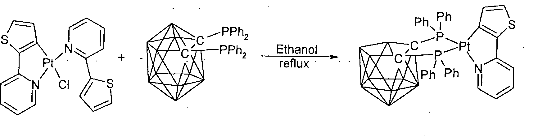
Die hierin gezeigten Beispiele [Pt(ppy)(7a)] und [Pt(thpy)(7a)] (thpy = 2-(2-Thienyl)-Pyridin) belegen, dass die Liganden 7 die Aggregation der quadratisch-planaren Komplexe blockieren und die emittierenden Chromophorzentren sterisch isolieren. Dadurch ist es auch möglich, im Festkörper (100% Emitterschicht) hohe Lumineszenzquantenausbeuten der Monomere zu erreichen.The herein shown examples [Pt (ppy) (7a)] and [Pt (thpy) (7a)] (thpy = 2- (2-thienyl) -pyridine) show that the ligands 7 aggregation of the square-planar complexes and the emitting chromophore centers isolate sterically. As a result, it is also possible in the solid state (100% emitter layer) high luminescence quantum yields of the monomers to reach.
Für
die Synthese von Metal-Komplexen mit den Liganden 7 kann man diese
Liganden in Form eines löslichen Salzes (z. B. mit dem
N(C4H9)4 + Gegenion). verwenden (siehe Beispiel 3).
Alternativ kann man von einem neutralen closo-Carboren-Diphosphan
oder Diarsan B10H10C2(ER2)2 8
ausgehen (siehe Beispiele 1 und 2). 8a (E = P, R = Ph) wurde bereits
1963 gemäß Gl. 1 aus dem 1,2-Carboran durch Umsetzung
mit nBuLi und Ph2PCl erhalten (

Neben
den symmetrisch substituierten bis-Phosphan- und bis-Arsan-Carboranen
sind auch unsymmetrisch substituierte Derivative, z. B. (B10H10C2)(PR2)(AsR2) zugänglich.
Bei der Synthese solcher Verbindungen ist die Verwendung von Schutzgruppen
notwendig. Für den Schutz der C-H Funktion in Carboranen
können z. B. Halogenalkylsilane verwendet werden (
Die erfindungsgemäßen Komplexe weisen ein Zentralatom auf, bei welchem es sich um ein Metall handelt. Vorzugsweise ist M ein einzelnes Metall-Ion oder Metall-Atom. M ist insbesondere ein Übergangsmetall und wird bevorzugt ausgewählt aus Pt, Pd, Hg, Rh, Ir, Re, Ru, Cu, Os oder W. Das Zentralatom liegt bevorzugt als Pd(II), Hg(II), Pt(II), Pt(IV), Rh(III), Ir (I), Ir (III), Re(I), Ru(II), Cu(I), Rh(I), Os(II) oder W(0) vor, also als Atom oder als einfach oder zweifach oder dreifach positiv geladenes Ion. Besonders bevorzugt ist das Zentralatom Pt(II) oder Cu(I).The Complexes according to the invention have a central atom on, which is a metal. Preferably M is a single metal ion or metal atom. M is particular a transition metal and is preferably selected from Pt, Pd, Hg, Rh, Ir, Re, Ru, Cu, Os or W. The central atom lies preferably as Pd (II), Hg (II), Pt (II), Pt (IV), Rh (III), Ir (I), Ir (III), Re (I), Ru (II), Cu (I), Rh (I), Os (II) or W (0), ie as Atom or as singly or doubly or triply positively charged Ion. The central atom is particularly preferably Pt (II) or Cu (I).
In einer bevorzugten Ausführungsform umfassen die erfindungsgemäßen Komplexe ein vierfach-koordiniertes Metall-Ion oder Metall-Atom. Solche Komplexe weisen insbesondere die Formel M (E ∩ E–)(A ∩ An–) auf. Das Metall-Ion ist in solchen Komplexen bevorzugt Pt(II), Ir(I), Cu(I), Rh(I) oder Pd(II).In a preferred embodiment, the complexes of the invention comprise a four-coordinate metal ion or metal atom. Such complexes have in particular the formula M (E ∩ E - ) (A ∩ A n- ). The metal ion in such complexes is preferably Pt (II), Ir (I), Cu (I), Rh (I) or Pd (II).
In einer weiteren Ausführungsform umfassen die erfindungsgemäßen Komplexe ein sechsfach-koordiniertes Metall-Ion oder Metall-Atom. Solche Komplexe weisen insbesondere die Formel M (E ∩ E)(A ∩ An–)2, M(E ∩ E–)2 (A ∩ An–) oder M (E ∩ E–)(A ∩ An–)(L)2 auf. Das Metall-Ion oder Metall-Atom ist in solchen Komplexen bevorzugt Os(II), Ir(III), Ru(II), Re(I), Pt(IV) oder W(0).In a further embodiment, the complexes of the invention comprise a six-coordinate metal ion or metal atom. Such complexes have in particular the formula M (E ∩ E) (A ∩ A n-) 2, M (E ∩ E -) 2 (A ∩ A n-) or M (E ∩ E -) (A ∩ A n- ) (L) 2 . The metal ion or metal atom in such complexes is preferably Os (II), Ir (III), Ru (II), Re (I), Pt (IV) or W (0).
(A ∩ An–) stellt erfindungsgemäß einen Chromophorliganden dar. Dieser Ligand ist neutral oder negativ geladen, insbesondere einfach negativ geladen. Die Bindung von (A ∩ An–) an das Metall im erfindungsgemäßen Komplex erfolgt bevorzugt durch ein Kohlenstoffatom oder durch ein Stickstoffatom, d. h. es besteht ein direkter Kontakt zwischen dem Metall-Atom und einer aromatischen oder konjugierten Gruppierung des Liganden. Das Kohlenstoffatom kann auch eine Carben-Funktion haben. Der Ligand (A ∩ An–) umfasst vorzugsweise aromatische Gruppierungen und insbesondere zwei aromatische Gruppierungen (Ar-Ar). Bevorzugte Gruppierungen sind in den Ansprüchen angegeben.(A ∩ A n- ) represents according to the invention a chromophore ligand. This ligand is neutral or negatively charged, in particular simply negatively charged. The bonding of (A ∩ A n- ) to the metal in the complex according to the invention is preferably carried out by a carbon atom or by a nitrogen atom, ie there is a direct contact between the metal atom and an aromatic or conjugated moiety of the ligand. The carbon atom may also have a carbene function. The ligand (A ∩ A n- ) preferably comprises aromatic moieties and in particular two aromatic moieties (Ar-Ar). Preferred groupings are given in the claims.
Die Erfindung umfasst weiterhin eine Licht emittierende Vorrichtung umfassend (i) eine Anode, (ii) eine Kathode und (iii) eine Emitterschicht, angeordnet zwischen und in direktem oder indirektem Kontakt mit der Anode und der Kathode, umfassend wenigstens einen Komplex, umfassend einen Hilfsliganden der Formel (I), insbesondere einen Komplex der Formel (II).The The invention further comprises a light-emitting device comprising (i) an anode, (ii) a cathode and (iii) an emitter layer between and in direct or indirect contact with the anode and the cathode comprising at least one complex comprising one Auxiliary ligands of the formula (I), in particular a complex of the formula (II).
Es wurde festgestellt, dass durch den erfindungsgemäßen Einsatz von Komplexen, umfassend einen Hilfsliganden der Formel (I) in der Emitterschicht Licht emittierende Vorrichtungen erhalten werden können, die hervorragende Eigenschaften aufweisen. Insbesondere zeigen die erfindungsgemäß eingesetzten Verbindungen hohe Quantenausbeuten. Die Komplexe können zudem durch Substitution oder/und Veränderung der Liganden variiert werden, wodurch sich vielfältige Möglichkeiten zur Modifizierung bzw. Steuerung der Emissionseigenschaften ergeben. Durch geeignete Wahl der Liganden können zudem Verbindungen mit hoher Sublimierbarkeit erhalten werden.It was found that by the invention Use of complexes comprising an auxiliary ligand of the formula (I) in the emitter layer light emitting devices which have excellent properties. In particular, the inventively used Compounds high quantum yields. The complexes can also by substitution and / or modification of the ligands be varied, resulting in many possibilities for modifying or controlling the emission properties. By suitable choice of ligands can also compounds obtained with high sublimability.
Die
Funktionsweise einer Ausführungsform der erfindungsgemäßen
Licht emittierenden Vorrichtungen ist schematisch in
Die
erfindungsgemäßen Licht emittierenden Vorrichtungen
können, soweit die Emittermaterialien sublimierbar sind, über
Vakuumdeposition hergestellt werden. Alternativ ist auch ein Aufbau über
nass-chemische Auftragung möglich, beispielsweise über
Spin-Coating-Verfahren, über Inkjet-Printen oder über
Siebdruckverfahren. Der Aufbau von OLED-Vorrichtungen wird beispielsweise
in
Die erfindungsgemäßen Licht emittierenden Vorrichtungen können mittels der Vakuum-Sublimations-Technik gefertigt werden und mehrere weitere Schichten enthalten, insbesondere eine Elektronen-Injektionsschicht und eine Elektronen-Leitungsschicht (z. B. Alq3 = Al-8-hydroxychinolin oder β-Alq = Al-bis(2-methyl-8-hydroxychinolato)-4-phenylphenolat) und/oder eine Loch-Injektions- (z. B. CuPc) und Loch-Leitungsschicht oder Loch-Leitungsschicht (z. B. α-NPD). Es ist aber auch möglich, dass die Emitterschicht Funktionen der Loch- bzw. Elektronen-Leitungsschicht übernimmt.The light-emitting devices according to the invention can be manufactured by means of the vacuum sublimation technique and comprise a plurality of further layers, in particular an electron injection layer and an electron conducting layer (eg Alq 3 = Al-8-hydroxyquinoline or β-Alq = Al bis (2-methyl-8-hydroxyquinolato) -4-phenylphenolate) and / or a hole injection (e.g., CuPc) and hole conduction layer or hole conduction layer (e.g., α-NPD). But it is also possible that the emitter layer takes over functions of the hole or electron conduction layer.
Die Emitterschicht besteht vorzugsweise aus einem organischen Matrixmaterial mit ausreichend großem Singulett S0 – Triplett T1 – Energieabstand (UGH-Matrix-Material), z. B. aus UGH, PVK (Polyvinylcarbazol), CBP (4,4'-Bis(9-carbazolyl)biphenyl) oder anderen Matrixmaterialien. In dieses Matrixmaterial wird der Emitter-Komplex eindotiert, z. B. bevorzugt mit 1 bis 100, insbesondere mit 3 bis 12 Gewichtsprozent.The emitter layer preferably consists of an organic matrix material with a sufficiently large singlet S 0 - triplet T 1 - energy gap (UGH matrix material), z. From UGH, PVK (polyvinylcarbazole), CBP (4,4'-bis (9-carbazolyl) biphenyl) or other matrix materials. In this matrix material, the emitter complex is doped, z. B. preferably 1 to 100, especially 3 to 12 weight percent.
Die Emitterschicht kann auch ohne Matrix realisiert werden, indem der entsprechende Komplex als 100%-Material aufgebracht wird.The Emitter layer can also be realized without matrix by the corresponding complex is applied as 100% material.
In einer besonders bevorzugten Ausführungsform weist die erfindungsgemäße Licht emittierende Vorrichtung zwischen der Kathode und der Emitterschicht oder einer Elektronenleiterschicht noch eine CsF Zwischenschicht auf. Diese Schicht weist insbesondere eine Dicke von 0,5 nm bis 2 nm, bevorzugt von ca. 1 nm auf. Diese Zwischenschicht bewirkt vorwiegend eine Reduzierung der Elektronenaustrittsarbeit.In a particularly preferred embodiment, the inventive Light emitting device between the cathode and the emitter layer or an electron conductor layer nor a CsF intermediate layer on. This layer has in particular a thickness of 0.5 nm 2 nm, preferably from about 1 nm. This intermediate layer causes mainly a reduction of the electron work function.
Weiterhin bevorzugt wird die Licht emittierende Vorrichtung auf einem Substrat aufgebracht, beispielsweise auf einem Glassubstrat.Farther preferably, the light-emitting device is mounted on a substrate applied, for example on a glass substrate.
Zum Beispiel lassen sich in einem typischen OLED-Schichtaufbau, bestehend aus einer ITO-Anode, einem Lochleiter aus PEDOT/PSS, der erfindungsgemäßen Emitterschicht, gegebenenfalls einer Lochblockierschicht, einer Elektronenleiterschicht, einer dünnen LiF- oder CsF-Zwischenschicht zur Verbesserung der Elektroneninjektion sowie einer Metall-Elektrode (Kathode) gute Leistungseffizienzen erzielen. Diese verschiedenen Schichten mit einer Gesamtdicke von einigen 100 nm lassen sich z. B. auf einem Glassubstrat oder einem sonstigen Trägermaterial aufbringen.To the Example can be in a typical OLED layer structure, consisting from an ITO anode, a hole conductor made of PEDOT / PSS, the invention Emitter layer, optionally a hole blocking layer, one Electron conductor layer, a thin LiF or CsF intermediate layer for improving the electron injection and a metal electrode (Cathode) achieve good power efficiencies. These different Layers with a total thickness of some 100 nm can be z. B. on a glass substrate or other carrier material muster.
Das OLED-Device kann teils nasschemisch gefertigt werden, und zwar zum Beispiel gemäß folgendem Aufbau: Glassubstrat, durchsichtige ITO-Schicht (aus Indium-Zinn-Oxid), z. B. PEDOT/PSS (Polyethylendioxythiophen/Polystyrolsulfonsäure, z. B. 40 nm) oder andere, die Lochinjektion verbessernde Schichten, 100% erfindungsgemäßer Komplex (z. B. 10 bis 80 nm) oder eindotiert (z. B. 1%, insbesondere 4% bis 10%) in eine geeignete Matrix (z. B. 40 nm), aufgedampftes Alq3 (z. B. 40 nm), aufgedampftes LiF oder CsF als Schutzschicht (z. B. 0,8 nm), aufgedampfte Metallkathode Al oder Ag oder Mg/Ag (z. B. 200 nm).The OLED device can be made partially wet-chemically, for example according to the following structure: glass substrate, transparent ITO layer (made of indium tin oxide), for. PEDOT / PSS (polyethylenedioxythiophene / polystyrenesulfonic acid, eg 40 nm) or other hole injection enhancing layers, 100% inventive complex (eg 10 to 80 nm) or doped (eg 1%, especially 4% to 10%) in a suitable matrix (eg 40 nm), evaporated Alq 3 (e.g. 40 nm), evaporated LiF or CsF as protective layer (eg 0.8 nm), evaporated metal cathode Al or Ag or Mg / Ag (eg 200 nm).
Besonders
bevorzugt weist ein OLED-Aufbau für einen löslichen,
erfindungsgemäßen Emitter die im Folgenden beschriebene
und in
Die Vorrichtung wird vorzugsweise auf ein Trägermaterial aufgebracht, insbesondere auf Glas oder ein anderes festes oder flexibles durchsichtiges Material. Auf das Trägermaterial, wird eine Anode aufgebracht, beispielsweise eine Indium-Zinn-Oxid-Anode. Die Schichtdicke der Anode beträgt vorzugsweise 10 nm bis 100 nm, insbesondere 30 bis 50 nm. Auf die Anode und zwischen Anode und Emitterschicht wird eine HTL-Schicht aus einem Lochleitermaterial aufgebracht, insbesondere aus einem Lochleitermaterial, welches wasserlöslich ist. Ein solches Lochleitermaterial sind beispielsweise PEDOT/PSS (Polyethylendioxythiophen/Poly styrolsulfonsäure) oder neue HTL-Materialien (Fa. DuPont) zur Verlängerung der Device-Lebensdauer. Die Schichtdicke der HTL-Schicht beträgt vorzugsweise 10 bis 100 nm, insbesondere 40 bis 60 nm. Als Nächstes wird die Emitterschicht (EML) aufgebracht, welche einen erfindungsgemäßen löslichen Emitter enthält. Das Material kann in einem Lösungsmittel, beispielsweise in Aceton, Dichlormethan oder Acetonitril, gelöst werden. Dadurch kann ein Auflösen der darunterliegenden PEDOT/PSS-Schicht vermieden werden. Das erfindungsgemäße Emittermaterial kann in geringer Konzentration, z. B. 3 bis 12 Gew.-%, aber auch in höherer Konzentration oder als 100%-Schicht eingesetzt werden. Bevorzugt werden Metall-Komplexe umfassend einen Hilfsliganden in einer Konzentration eingebracht, die eine Triplett-Triplett-Annihilation verhindert oder stark einschränkt, insbesondere in einer Konzentration von insgesamt größer 3 Gew.-% und kleiner 12 Gew.-%. Es ist auch möglich, das Emittermaterial hoch- oder mitteldotiert in einer geeigneten Polymerschicht (z. B. PVK) aufzubringen. Für schlecht lösliche, erfindungsgemäße Emittermaterialien kann das Auftragen durch eine kolloidale Suspension in einem Polymer durchgeführt werden. Die Emitterschicht weist vorzugsweise eine Schichtdicke von 30 bis 100 nm, insbesondere von 40 bis 80 nm auf. Auf die Emitterschicht wird vorzugsweise eine Schicht aus Elektronentransportmaterial aufgebracht, insbesondere mit einer Schichtdicke von 10 bis 80 nm, mehr bevorzugt von 30 bis 50 nm. Ein geeignetes Material für die Elektronentransportmaterialschicht (ETL) ist beispielsweise Alq3, welches aufdampfbar ist. Als Nächstes wird vorzugsweise eine dünne Zwischenschicht aufgebracht, welche die Elektroneninjektionsbarriere verringert und die ETL-Schicht schützt. Diese Schicht weist vorzugsweise eine Dicke zwischen 0,1 und 2 nm, insbesondere zwischen 0,5 und 1,5 nm auf und besteht vorzugsweise aus CsF oder LiF. Diese Schicht wird in der Regel aufgedampft. Für einen weiter vereinfachten OLED-Aufbau können gegebenenfalls der ETL- und/oder die Zwischenschicht entfallen.The device is preferably applied to a carrier material, in particular to glass or another solid or flexible transparent material. On the substrate, an anode is applied, for example, an indium tin oxide anode. The layer thickness of the anode is preferably 10 nm to 100 nm, in particular 30 to 50 nm. An HTL layer of a hole conductor material is applied to the anode and between the anode and emitter layer, in particular of a hole conductor material which is water-soluble. Such a hole conductor material are, for example PEDOT / PSS (Polyethylendioxythiophen / poly styrenesulfonic acid) or new HTL materials (DuPont) to extend the device life. The layer thickness of the HTL layer is preferably 10 to 100 nm, in particular 40 to 60 nm. Next, the emitter layer (EML) is applied, which contains a soluble emitter according to the invention. The material can be dissolved in a solvent, for example in acetone, dichloromethane or acetonitrile. As a result, a dissolution of the underlying PEDOT / PSS layer can be avoided. The emitter material according to the invention can be used in low concentration, for. B. 3 to 12 wt .-%, but also be used in higher concentration or as a 100% layer. Preference is given to introducing metal complexes comprising an auxiliary ligand in a concentration which prevents or severely restricts triplet triplet annihilation, in particular in a concentration of altogether greater than 3% by weight and less than 12% by weight. It is also possible to apply the emitter material highly or moderately doped in a suitable polymer layer (eg PVK). For poorly soluble emitter materials according to the invention, the application can be carried out by a colloidal suspension in a polymer. The emitter layer preferably has a layer thickness of 30 to 100 nm, in particular from 40 to 80 nm. A layer of electron transport material is preferably applied to the emitter layer, in particular with a layer thickness of 10 to 80 nm, more preferably 30 to 50 nm. A suitable material for the electron transport material layer (ETL) is, for example, Alq 3 , which is vapor-deposited. Next, a thin intermediate layer is preferably applied which reduces the electron injection barrier and protects the ETL layer. This layer preferably has a thickness between 0.1 and 2 nm, in particular between 0.5 and 1.5 nm, and preferably consists of CsF or LiF. This layer is usually applied by evaporation. For a further simplified OLED structure, the ETL and / or the interlayer may optionally be omitted.
Schließlich wird eine leitende Kathodenschicht aufgebracht, insbesondere aufgedampft. Die Kathodenschicht besteht vorzugsweise aus einem Metall, insbesondere aus Al oder Mg/Ag (insbesondere im Verhältnis 10:1).After all a conductive cathode layer is applied, in particular vapor-deposited. The cathode layer is preferably made of a metal, in particular from Al or Mg / Ag (in particular in the ratio 10: 1).
An die Vorrichtung werden vorzugsweise Spannungen von 3 bis 15 V angelegt.At the device is preferably applied voltages of 3 to 15V.
In
einer bevorzugten Ausführungsform umfasst ein OLED-Aufbau
für einen sublimierbaren erfindungsgemäßen
Emitter neben einer Anode, Emitterschicht und Kathode auch noch
wenigstens eine, insbesondere mehrere und besonders bevorzugt alle
der nachfolgend genannten und in
Der gesamte Aufbau befindet sich vorzugsweise auf einem Trägermaterial, wobei hierfür insbesondere Glas oder jedes andere feste oder flexible durchsichtige Material eingesetzt werden kann. Auf dem Trägermaterial wird die Anode angeordnet, beispielsweise eine Indium-Zinn-Oxid-Anode (ITO). Auf die Anode und zwischen Emitterschicht und Anode wird eine Lochtransportschicht (HTL, hole transport layer) angeordnet, beispielsweise α-NPD. Die Dicke der Lochtransportschicht beträgt vorzugsweise 10 bis 100 nm, insbesondere 30 bis 50 nm. Zwischen der Anode und der Lochtransportschicht können weitere Schichten angeordnet sein, die die Lochinjektion verbessern, z. B. eine Kupfer-Phthalocyanin (CuPc)-Schicht. Diese Schicht ist bevorzugt 5 bis 50, insbesondere 8 bis 15 nm dick. Auf die Lochtransportschicht und zwischen Lochtransport- und Emitterschicht wird vorzugsweise eine Elektronenblockierschicht aufgetragen, die dafür sorgt, dass der Elektronentransport zur Anode unterbunden wird, da ein solcher Strom nur Ohm'sche Verluste verursachen würde. Die Dicke dieser Elektronenblockierschicht beträgt vorzugsweise 10 bis 100 nm, insbesondere 20 bis 40 nm. Auf diese zusätzliche Schicht kann insbesondere dann verzichtet werden, wenn die HTL-Schicht bereits intrinsisch ein schlechter Elektronenleiter ist.Of the entire structure is preferably on a carrier material, in particular glass or any other solid or flexible transparent material can be used. On the carrier material, the anode is arranged, for example an indium tin oxide anode (ITO). On the anode and between emitter layer and anode becomes a hole transport layer (HTL, hole transport layer) arranged, for example α-NPD. The thickness of the hole transport layer is preferably 10 to 100 nm, in particular 30 to 50 nm. Between the anode and the hole transport layer can be arranged further layers that improve the hole injection, z. B. a copper phthalocyanine (CuPc) layer. This layer is preferably 5 to 50, in particular 8 to 15 nm thick. On the hole transport layer and between hole transport and emitter layer is preferably applied an electron blocking layer, which ensures that the electron transport is suppressed to the anode, as a such current would only cause ohmic losses. The thickness of this electron blocking layer is preferably 10 to 100 nm, in particular 20 to 40 nm. On this additional Layer can be omitted in particular if the HTL layer already intrinsically a bad electron conductor.
Bei
der nächsten Schicht handelt es sich um die Emitterschicht,
die das erfindungsgemäße Emittermaterial enthält
oder aus diesem besteht. In der Ausführungsform unter Verwendung
von sublimierbaren Emittern werden die Emittermaterialien bevorzugt
durch Sublimation aufgetragen. Die Schichtdicke beträgt
vorzugsweise zwischen 10 nm und 200 nm, insbesondere zwischen 50
nm und 150 nm. Das erfindungsgemäße Emittermaterial
kann auch gemeinsam mit anderen Materialien, insbesondere mit Matrixmaterialien
koverdampft werden. Für im Grünen oder Roten emittierende
erfindungsgemäße Emittermaterialien eignen sich gängige
Matrixmaterialien wie PVK oder CBP (4,4'-Bis-(N-carbazolyl)biphenyl).
Es ist aber auch möglich, eine 100%-Emittermaterial-Schicht
aufzubauen. Für im Blauen emittierende erfindungsgemäße
Emittermaterialien werden vorzugsweise UHG-Matrixmaterialien eingesetzt
(vgl.
Grundsätzlich können erfindungsgemäß gängige Matrixmaterialien für OLEDs, aber auch weitgehend inerte Polymere bzw. kleine Matrixmoleküle ohne besonders ausgeprägte Loch- oder Elektronenmobilitäten als Matrixmaterialien eingesetzt werden.in principle can according to the invention common Matrix materials for OLEDs, but also largely inert Polymers or small matrix molecules without pronounced Hole or electron mobilities as matrix materials be used.
Auf die Emitterschicht wird vorzugsweise eine Hole-Blocking-Schicht aufgetragen, welche Ohm'sche Verluste reduziert, die durch Lochströme zur Kathode entstehen könnten. Diese Hole-Blocking-Schicht ist vorzugsweise 10 bis 50 nm, insbesondere 15 bis 25 nm dick. Ein geeignetes Material hierfür ist beispielsweise BCP (4,7-Diphenyl-2,9-dimethyl-phenanhrolin, auch Bathocuproin genannt). Auf die Hole-Blocking-Schicht und zwischen diese Schicht und die Kathode wird vorzugsweise eine ETL-Schicht aus Elektronentransportmaterial (ETL = electron transport layer) aufgebracht. Vorzugsweise besteht diese Schicht aus aufdampfbarem Alq3 mit einer Dicke von 10 bis 100 nm, insbesondere von 30 bis 50 nm. Zwischen die ETL-Schicht und die Kathode wird vorzugsweise eine Zwischenschicht aufgebracht, beispielsweise aus CsF oder LiF. Diese Zwischenschicht verringert die Elektroneninjektionsbarriere und schützt die ETL-Schicht. Diese Schicht wird in der Regel aufgedampft. Die Zwischenschicht ist vorzugsweise sehr dünn, insbesondere 0,2 bis 5 nm, mehr bevorzugt 0,5 bis 2 nm dick. Schließlich wird noch eine leitende Kathodenschicht aufgedampft, insbesondere mit einer Dicke von 50 bis 500 nm, mehr bevorzugt von 100 bis 250 nm. Die Kathodenschicht besteht vorzugsweise aus Al, Mg/Ag (insbesondere im Verhältnis 10:1) oder anderen Metallen. An den beschriebenen OLED-Aufbau für einen sublimierbaren erfindungsgemäßen Emitter werden vorzugsweise Spannungen zwischen 3 und 15 V angelegt.On the emitter layer, a hole-blocking layer is preferably applied, which reduces ohmic losses that could arise through hole currents to the cathode. This hole-blocking layer is preferably 10 to 50 nm, in particular 15 to 25 nm thick. A suitable material for this is, for example, BCP (4,7-diphenyl-2,9-dimethyl-phenanhroline, also called bathocuproine). An ETL layer of electron transport layer (ETL) is preferably applied to the hole-blocking layer and between this layer and the cathode. Preferably, this layer consists of vapor-deposited Alq 3 with a thickness of 10 to 100 nm, in particular from 30 to 50 nm. Between the ETL layer and the cathode, an intermediate layer is preferably applied, for example from CsF or LiF. This interlayer reduces the electron injection barrier and protects the ETL layer. This layer is usually applied by evaporation. The intermediate layer is preferably very thin, in particular 0.2 to 5 nm, more preferably 0.5 to 2 nm thick. Finally, a conductive cathode layer is evaporated, in particular with a thickness of 50 to 500 nm, more preferably 100 to 250 nm. The cathode layer is preferably made of Al, Mg / Ag (in particular in the ratio 10: 1) or other metals. Voltages between 3 and 15 V are preferably applied to the described OLED structure for a sublimable emitter according to the invention.
Erfindungswesentlich ist, dass die Licht emittierende Vorrichtung als Emitter wenigstens einen Komplex umfassend einen Hilfsliganden der Formel (I) enthält.essential to the invention is that the light-emitting device as an emitter at least a complex comprising an auxiliary ligand of the formula (I).
Erfindungsgemäß wurde nun festgestellt, dass Metall-Komplexe umfassend Hilfsliganden der Formel (I) hervorragend für optoelektronische Anwendungen und insbesondere als Emitter-Moleküle für Licht emittierende Vorrichtungen und insbesondere für organische Licht emittierende Vorrichtungen (OLEDs) geeignet sind.According to the invention was now found that metal complexes comprising auxiliary ligands of Formula (I) excellent for opto-electronic applications and especially as emitter molecules for light emitting devices and in particular for organic Light emitting devices (OLEDs) are suitable.
Erfindungsgemäß bevorzugt werden als Emitter-Moleküle Komplexe umfassend Hilfsliganden der Formel (I) eingesetzt. Bei diesen Komplexen handelt es sich insbesondere um lumineszierende oder elektrolumineszierende Verbindungen.According to the invention preferred are used as emitter molecules complexes comprising auxiliary ligands of the formula (I) used. These complexes are in particular luminescent or electroluminescent compounds.
Die Erfindung wird durch die beigefügten Figuren und die nachfolgenden Beispiele weiter erläutert.The Invention is by the attached figures and the following Examples further explained.
BeispieleExamples
Beispiel 1: Pt(ppy)(7a)Example 1: Pt (ppy) (7a)
Synthesesynthesis
Der Komplex Pt(ppy)(7a) wird durch Reaktion von Pt(ppy)(ppyH)Cl und 1,2-Bis-(diphenylphosphan)-closo-Carboran hergestellt (Gl. 2). Äquimolare Mengen an Pt(ppy)(ppyH)Cl und 1,2-bis(Diphenylphosphan)-closo-Carboran werden unter Argon 12 h in Ethanol unter Rückfluss erhitzt. Nach Abkühlen auf Raumtemperatur wird das aus dem Reaktionsgemisch ausgefallene rohe Produkt chromatographisch gereinigt (Al2O3, Hexan/Dichloromethan). Die Reinigung erfolgt durch Kristallisation aus heißem Ethanol.The complex Pt (ppy) (7a) is prepared by the reaction of Pt (ppy) (ppyH) Cl and 1,2-bis (diphenylphosphine) -closo-carborane (equation 2). Equimolar amounts of Pt (ppy) (ppyH) Cl and 1,2-bis (diphenylphosphine) -closo-carborane are refluxed under argon for 12 h in ethanol. After cooling to room temperature, the crude product precipitated from the reaction mixture is purified by chromatography (Al 2 O 3 , hexane / dichloromethane). The purification is carried out by crystallization from hot ethanol.

Beispiel 2: Pt(thpy)(7a)Example 2: Pt (thpy) (7a)
Synthesesynthesis
Der Komplex Pt(thpy)(7a) wird aus Pt(thpy)(thpyH)Cl und 1,2-Bis-(diphenylphosphan)-closo-carboran hergestellt (Gl. 3). Eine Lösung aus äquimolaren Mengen von Pt(phpy)(phpyH)Cl und 1,2-Bis-(diphenylphosphan)-closo-carboran wird unter Argon 12 h in refluxierendem Ethanol gerührt. Nach Abkühlung wird das aus dem Reaktionsgemisch ausgefallene rohe Produkt chromatographisch gereinigt (Al2O3, Hexan/Dichloromethan). Zusätzlich wird das Produkt aus heißem Ethanol kristallisiert.Complex Pt (thpy) (7a) is prepared from Pt (thpy) (thpyH) Cl and 1,2-bis (diphenylphosphine) -closo-carborane (equation 3). A solution of equimolar amounts of Pt (phpy) (phpyH) Cl and 1,2-bis (diphenylphosphine) -closo-carborane is stirred under argon for 12 hours in refluxing ethanol. After cooling, the crude product precipitated from the reaction mixture is purified by chromatography (Al 2 O 3 , hexane / dichloromethane). In addition, the product is crystallized from hot ethanol.
Beispiel 3: Cu(dphen)(7a), (dpphen = 4,7-Diphenylphenanthrolin)Example 3: Cu (dphen) (7a), (dpphene = 4,7-diphenylphenanthroline)
Synthesesynthesis
Der Komplex Cu(dphen)(7a) (dpphen = 4,7-Diphenylphenanthrolin), wird aus [Cu(CH3CN)4]PF6, 7a und dphen hergestellt (Gl. 4). Eine Lösung aus äquimolaren Mengen von [Cu(CH3CN)4]PF6 und Tetrabutylammonium-7,8-Bis-(diphenylphosphino)-7,8-dicarba-nido-undecaborat ([NBu4](7a)) wird unter Argon 2 h in Dichloromethan gerührt. Zu dieser in situ hergestellten Lösung von [Cu(CH3CN)2(7a)] wird eine äquimolare Menge an dphen zugegeben. Nachdem die Lösung sich intensiv rot gefärbt hat, wird das Reaktionsgemisch chromatographiert (SiO2, CH2Cl2). Die weitere Reinigung erfolgt durch Kristallisation aus Dichloromethan/Hexan.The complex Cu (dphen) (7a) (dpphen = 4,7-diphenylphenanthroline) is prepared from [Cu (CH 3 CN) 4 ] PF 6 , 7a, and dphen (equation 4). A solution of equimolar amounts of [Cu (CH 3 CN) 4 ] PF 6 and tetrabutylammonium-7,8-bis (diphenylphosphino) -7,8-dicarba-nido-undecaborate ([NBu 4 ] (7a)) is added Argon stirred for 2 h in dichloromethane. To this in situ prepared solution of [Cu (CH 3 CN) 2 (7a)] is added an equimolar amount of dphen. After the solution has turned intensely red, the reaction mixture is chromatographed (SiO 2 , CH 2 Cl 2 ). Further purification is carried out by crystallization from dichloromethane / hexane.

ZITATE ENTHALTEN IN DER BESCHREIBUNGQUOTES INCLUDE IN THE DESCRIPTION
Diese Liste der vom Anmelder aufgeführten Dokumente wurde automatisiert erzeugt und ist ausschließlich zur besseren Information des Lesers aufgenommen. Die Liste ist nicht Bestandteil der deutschen Patent- bzw. Gebrauchsmusteranmeldung. Das DPMA übernimmt keinerlei Haftung für etwaige Fehler oder Auslassungen.This list The documents listed by the applicant have been automated generated and is solely for better information recorded by the reader. The list is not part of the German Patent or utility model application. The DPMA takes over no liability for any errors or omissions.
Zitierte PatentliteraturCited patent literature
- - US 2005/0260449 A1 [0036] US 2005/0260449 A1 [0036]
- - WO 2005/098988 A1 [0036] WO 2005/098988 A1 [0036]
Zitierte Nicht-PatentliteraturCited non-patent literature
- - H. Yersin, Top. Curr. Chem. 2004, 241,1 [0004] - H. Yersin, Top. Curr. Chem. 2004, 241, 1 [0004]
- - Tang et al., Appl. Phys. Lett. 51 (1987) 913 [0005] Tang et al., Appl. Phys. Lett. 51 (1987) 913 [0005]
- - J. Li, P. I. Djurovich, B. D. Alleyne, M. Yousufuddin, N. N. Ho, J. C. Thomas, J. C. Peters, R. Bau, M. E. Thompson, Inorg. Chem. 2005, 44, 1713 [0009] J. Li, PI Djurovich, BD Alleyne, M. Yousufuddin, NN Ho, JC Thomas, JC Peters, R. Bau, ME Thompson, Inorg. Chem. 2005, 44, 1713 [0009]
- - J. Li, P. I. Djurovich, B. D. Alleyne, I. Tsyba, N. N. Ho, R. Bau, M. E. Thompson, Polyhedron 2004, 23, 419 [0009] J. Li, PI Djurovich, BD Alleyne, I. Tsyba, NN Ho, R. Bau, ME Thompson, Polyhedron 2004, 23, 419 [0009]
- - F. Teixidor, C. Viñas, M. M. Abad, F. Teixidor, R. Sillanpää, J. Organomet. Chem., 1996, 509, 139 [0021] F. Teixidor, C. Viñas, MM Abad, F. Teixidor, R. Sillanpää, J. Organomet. Chem., 1996, 509, 139 [0021]
- - C. Viñas, M. M. Abad, F. Teixidor, R. Sillanpää, R. Kivekäs, J. Organomet. Chem., 1998, 555, 17 [0021] C. Viñas, MM Abad, F. Teixidor, R. Sillanpää, R. Kivekäs, J. Organomet. Chem., 1998, 555, 17 [0021]
- - D. Zhang, J. Dou, D. Li, D. Wang, Inorg. Chim. Acta, 2006, 359, 4243 [0021] D. Zhang, J. Dou, D. Li, D. Wang, Inorg. Chim. Acta, 2006, 359, 4243 [0021]
- - O. Crespo, M. C. Gimeno, P. G. Jones, A. Laguna, J. Chem. Soc., Dalton Trans., 1996, 4583 [0021] O. Crespo, MC Gimeno, PG Jones, A. Laguna, J. Chem. Soc., Dalton Trans., 1996, 4583 [0021]
- - M. J. Calhorda, O. Crespo, M. C. Gimeno, P. G. Jones, A. Laguna, J.-M. Lópezde-Luzuriaga, J. L. Perez, M. A. Ramón, L. F. Veiros, Inorg. Chem., 2000, 39, 4280 [0021] MJ Calhorda, O. Crespo, MC Gimeno, PG Jones, A. Laguna, J.-M. Lópezde-Luzuriaga, JL Perez, MA Ramón, LF Veiros, Inorg. Chem., 2000, 39, 4280 [0021]
- - O. Crespo, M. C. Gimeno, P. G. Jones, A. Laguna, Inorg. Chem., 1996, 35, 1361 [0021] - O. Crespo, MC Gimeno, PG Jones, A. Laguna, Inorg. Chem., 1996, 35, 1361 [0021]
- - O. Crespo, M. C. Gimeno, P. G. Jones, A. Laguna, J.-M. López-de-Luzuriaga, M. Monge, J. L. Perez, M. A. Ramón, Inorg. Chem., 2003, 42, 2061 [0021] O. Crespo, MC Gimeno, PG Jones, A. Laguna, J.-M. López-de-Luzuriaga, M. Monge, JL Perez, MA Ramón, Inorg. Chem., 2003, 42, 2061 [0021]
- - R. P. Alexander, H. Schroeder, Inorg. Chem. 1963, 2, 1107 [0027] - RP Alexander, H. Schroeder, Inorg. Chem. 1963, 2, 1107 [0027]
- - F. Teixidor, C. Vinas, M. M. Abad, R. Nunez, R. Kivekas, R. Sillanpäa, J. Organomet. Chem., 1995, 503, 193 [0027] F. Teixidor, C. Vinas, MM Abad, R. Nunez, R. Kivekas, R. Sillanpäa, J. Organomet. Chem., 1995, 503, 193 [0027]
- - F. A. Gomez, S. E. Johnson, M. F. Hawthorne, J. Am. Chem. Soc., 1991, 113, 95/5. [0028] FA Gomez, SE Johnson, MF Hawthorne, J. Am. Chem. Soc., 1991, 113, 95/5. [0028]
- - M.E. Thompson et al., Chem. Mater. 2004, 16, 4743 [0050] ME Thompson et al., Chem. Mater. 2004, 16, 4743 [0050]
Claims (23)


Priority Applications (7)
| Application Number | Priority Date | Filing Date | Title |
|---|---|---|---|
| DE102007031261A DE102007031261A1 (en) | 2007-07-05 | 2007-07-05 | Luminescent metal complexes with bulky auxiliary ligands |
| US12/667,611 US8658832B2 (en) | 2007-07-05 | 2008-07-03 | Luminescent metal complexes for organic electronic devices |
| JP2010513782A JP5539194B2 (en) | 2007-07-05 | 2008-07-03 | Luminescent metal complexes for organic electronic devices |
| PCT/EP2008/005426 WO2009003700A1 (en) | 2007-07-05 | 2008-07-03 | Luminescent metal complexes for organic electronic devices |
| CN200880023538.7A CN101687889B (en) | 2007-07-05 | 2008-07-03 | For the luminescent metal complexes of organic electronic devices |
| KR20107002545A KR101495376B1 (en) | 2007-07-05 | 2008-07-03 | Luminescent metal complexes for organic electronic devices |
| EP08773837.3A EP2173757B1 (en) | 2007-07-05 | 2008-07-03 | Luminescent metal complexes for organic electronic devices |
Applications Claiming Priority (1)
| Application Number | Priority Date | Filing Date | Title |
|---|---|---|---|
| DE102007031261A DE102007031261A1 (en) | 2007-07-05 | 2007-07-05 | Luminescent metal complexes with bulky auxiliary ligands |
Publications (1)
| Publication Number | Publication Date |
|---|---|
| DE102007031261A1 true DE102007031261A1 (en) | 2009-01-08 |
Family
ID=39865001
Family Applications (1)
| Application Number | Title | Priority Date | Filing Date |
|---|---|---|---|
| DE102007031261A Withdrawn DE102007031261A1 (en) | 2007-07-05 | 2007-07-05 | Luminescent metal complexes with bulky auxiliary ligands |
Country Status (7)
| Country | Link |
|---|---|
| US (1) | US8658832B2 (en) |
| EP (1) | EP2173757B1 (en) |
| JP (1) | JP5539194B2 (en) |
| KR (1) | KR101495376B1 (en) |
| CN (1) | CN101687889B (en) |
| DE (1) | DE102007031261A1 (en) |
| WO (1) | WO2009003700A1 (en) |
Cited By (6)
| Publication number | Priority date | Publication date | Assignee | Title |
|---|---|---|---|---|
| WO2010006666A1 (en) * | 2008-07-17 | 2010-01-21 | Merck Patent Gmbh | Organic electroluminescence device |
| WO2012010650A1 (en) * | 2010-07-20 | 2012-01-26 | Cynora Gmbh | Copper (i) complexes for optoelectronic devices |
| WO2012001002A3 (en) * | 2010-06-29 | 2012-03-08 | Cynora Gmbh | Singlet harvesting with organic molecules for optoelectronic devices |
| EP2988105A2 (en) | 2014-08-20 | 2016-02-24 | HST High Soft Tech GmbH | Device and method for the automatic recognition and classification of audible acoustic signals in a monitored area |
| US10312456B2 (en) | 2011-12-22 | 2019-06-04 | Cynora Gmbh | Organic molecules for OLEDs and other optoelectronic devices |
| EP3591725A1 (en) * | 2018-07-02 | 2020-01-08 | Novaled GmbH | Electronic device, method for preparing the same and a display device comprising the same |
Families Citing this family (27)
| Publication number | Priority date | Publication date | Assignee | Title |
|---|---|---|---|---|
| DE102008048336A1 (en) * | 2008-09-22 | 2010-03-25 | Merck Patent Gmbh | Mononuclear neutral copper (I) complexes and their use for the production of optoelectronic devices |
| KR101072814B1 (en) | 2009-03-27 | 2011-10-14 | 덕산하이메탈(주) | Benzo isoquinoline compound and organic electric device using same, terminal thereof |
| EP2366983B1 (en) | 2010-03-17 | 2020-04-29 | VEGA Grieshaber KG | Mobility recognition in filling level measurement devices |
| KR20130098345A (en) * | 2010-08-20 | 2013-09-04 | 바스프 에스이 | Process for preparing a propiolic acid or a derivative thereof |
| CN102456839A (en) * | 2010-10-21 | 2012-05-16 | 海洋王照明科技股份有限公司 | Organic electroluminescent device and preparation method thereof |
| WO2012056931A1 (en) * | 2010-10-28 | 2012-05-03 | 住友化学株式会社 | Phosphorescent light-emitting element |
| DE102011001368B4 (en) * | 2011-03-17 | 2013-01-31 | Bundesanstalt für Materialforschung und -Prüfung (BAM) | Lanthanoid chelates containing particles, their preparation and their use in bioanalysis |
| KR101881082B1 (en) | 2011-06-20 | 2018-07-24 | 삼성디스플레이 주식회사 | Carborane compound, organic light-emitting diode comprising the same and flat display device |
| EP2554956B1 (en) | 2011-08-04 | 2020-07-29 | VEGA Grieshaber KG | Tracking taking mobility into consideration |
| CN102516984B (en) * | 2011-11-09 | 2015-09-16 | 中国科学院福建物质结构研究所 | A kind of orange red phosphor crystal material and its production and use |
| CN104067400B (en) | 2011-11-30 | 2018-02-27 | 诺瓦尔德股份有限公司 | Organic electronic device |
| WO2013094834A1 (en) * | 2011-12-19 | 2013-06-27 | 율촌화학 주식회사 | Novel compound having stability, and charge transfer material and blue phosphorescent organic light emitting diode comprising same |
| EP3190120B1 (en) * | 2012-05-11 | 2021-11-17 | The University Of Tokyo | Catalyst for synthesizing polyolefins |
| US9299956B2 (en) * | 2012-06-13 | 2016-03-29 | Aixtron, Inc. | Method for deposition of high-performance coatings and encapsulated electronic devices |
| GB2508092B (en) * | 2012-10-31 | 2015-09-23 | Lg Display Co Ltd | Light emitting device and organic light emitting display device including the same |
| JP6360797B2 (en) * | 2012-12-26 | 2018-07-18 | 新日鉄住金化学株式会社 | Material for organic electroluminescence device and organic electroluminescence device using the same |
| US10497883B2 (en) | 2014-03-11 | 2019-12-03 | Kyulux, Inc. | Organic light-emitting device, host material, light-emitting material, and compound |
| KR102241664B1 (en) * | 2014-03-24 | 2021-04-19 | 닛테츠 케미컬 앤드 머티리얼 가부시키가이샤 | Organic-electroluminescent-element material and organic electroluminescent elements using same |
| KR102156094B1 (en) * | 2014-03-24 | 2020-09-15 | 닛테츠 케미컬 앤드 머티리얼 가부시키가이샤 | Organic-electroluminescent-element material and organic electroluminescent element using same |
| US10998507B2 (en) | 2015-11-23 | 2021-05-04 | Universal Display Corporation | Organic electroluminescent materials and devices |
| CN106565789A (en) * | 2016-03-29 | 2017-04-19 | 上饶师范学院 | A nido-carborane containing organometallic compound crystal and a preparing method thereof |
| CN106800658B (en) * | 2017-01-17 | 2020-04-24 | 哈尔滨工业大学 | 4- (1H-tetrazole-5-yl) phenol lead coordination polymer and synthesis method and application thereof |
| US10978647B2 (en) | 2017-02-15 | 2021-04-13 | Universal Display Corporation | Organic electroluminescent materials and devices |
| US10741780B2 (en) | 2017-03-10 | 2020-08-11 | Universal Display Corporation | Organic electroluminescent materials and devices |
| CN109503667B (en) * | 2018-12-28 | 2020-09-08 | 西安交通大学 | Three-ligand synergistic enhanced aggregation-induced emission organometallic platinum complex luminescent material |
| CN111799381B (en) * | 2020-09-10 | 2020-11-27 | 江西省科学院能源研究所 | Preparation method of perovskite solar cell based on phosphorus-containing hole dopant |
| US20230133787A1 (en) * | 2021-06-08 | 2023-05-04 | University Of Southern California | Molecular Alignment of Homoleptic Iridium Phosphors |
Citations (5)
| Publication number | Priority date | Publication date | Assignee | Title |
|---|---|---|---|---|
| WO2005056712A1 (en) * | 2003-12-12 | 2005-06-23 | Basf Aktiengesellschaft | Use of platinum ii complexes as luminescent materials in organic light-emitting diodes (oleds) |
| DE10361385A1 (en) * | 2003-12-29 | 2005-10-13 | Osram Opto Semiconductors Gmbh | Polymers, phosphorescent organic semiconducting emitter materials based on perarylated boranes, process for their preparation and uses thereof |
| WO2005098988A1 (en) | 2004-04-08 | 2005-10-20 | Basf Aktiengesellschaft | Use of metallocene complexes of metals in the 4th sub-group of the periodic table as triple emitters in organic light-emitting diodes (oleds) |
| US20050260449A1 (en) | 2004-05-18 | 2005-11-24 | Robert Walters | Complexes with tridentate ligands |
| WO2007118671A1 (en) * | 2006-04-13 | 2007-10-25 | Universität Regensburg | Biphenyl/metal complex monomers and oligomeric triplet emitters for oled applications |
Family Cites Families (14)
| Publication number | Priority date | Publication date | Assignee | Title |
|---|---|---|---|---|
| US6660410B2 (en) | 2000-03-27 | 2003-12-09 | Idemitsu Kosan Co., Ltd. | Organic electroluminescence element |
| JP2004288318A (en) | 2003-03-24 | 2004-10-14 | Funai Electric Co Ltd | Discarding device for storage medium |
| EP1618170A2 (en) | 2003-04-15 | 2006-01-25 | Covion Organic Semiconductors GmbH | Mixtures of matrix materials and organic semiconductors capable of emission, use of the same and electronic components containing said mixtures |
| JP4635870B2 (en) | 2003-04-23 | 2011-02-23 | コニカミノルタホールディングス株式会社 | Organic electroluminescence element, lighting device and display device |
| JP4773346B2 (en) * | 2003-07-07 | 2011-09-14 | メルク パテント ゲーエムベーハー | Mixtures of organic light emitting semiconductors and matrix materials, their use and electronic components comprising said materials. |
| DE10333232A1 (en) | 2003-07-21 | 2007-10-11 | Merck Patent Gmbh | Organic electroluminescent element |
| US7795801B2 (en) * | 2003-09-30 | 2010-09-14 | Konica Minolta Holdings, Inc. | Organic electroluminescent element, illuminator, display and compound |
| DE102004010954A1 (en) * | 2004-03-03 | 2005-10-06 | Novaled Gmbh | Use of a metal complex as an n-dopant for an organic semiconductive matrix material, organic semiconductor material and electronic component |
| US7790890B2 (en) | 2004-03-31 | 2010-09-07 | Konica Minolta Holdings, Inc. | Organic electroluminescence element material, organic electroluminescence element, display device and illumination device |
| DE102004023277A1 (en) | 2004-05-11 | 2005-12-01 | Covion Organic Semiconductors Gmbh | New material mixtures for electroluminescence |
| JP4862248B2 (en) | 2004-06-04 | 2012-01-25 | コニカミノルタホールディングス株式会社 | Organic electroluminescence element, lighting device and display device |
| EP1888706B1 (en) | 2005-05-03 | 2017-03-01 | Merck Patent GmbH | Organic electroluminescent device and boric acid and borinic acid derivatives used therein |
| DE102006025777A1 (en) | 2006-05-31 | 2007-12-06 | Merck Patent Gmbh | New materials for organic electroluminescent devices |
| DE102007002714A1 (en) * | 2007-01-18 | 2008-07-31 | Merck Patent Gmbh | New materials for organic electroluminescent devices |
-
2007
- 2007-07-05 DE DE102007031261A patent/DE102007031261A1/en not_active Withdrawn
-
2008
- 2008-07-03 CN CN200880023538.7A patent/CN101687889B/en not_active Expired - Fee Related
- 2008-07-03 WO PCT/EP2008/005426 patent/WO2009003700A1/en not_active Ceased
- 2008-07-03 JP JP2010513782A patent/JP5539194B2/en not_active Expired - Fee Related
- 2008-07-03 US US12/667,611 patent/US8658832B2/en not_active Expired - Fee Related
- 2008-07-03 EP EP08773837.3A patent/EP2173757B1/en not_active Not-in-force
- 2008-07-03 KR KR20107002545A patent/KR101495376B1/en not_active Expired - Fee Related
Patent Citations (5)
| Publication number | Priority date | Publication date | Assignee | Title |
|---|---|---|---|---|
| WO2005056712A1 (en) * | 2003-12-12 | 2005-06-23 | Basf Aktiengesellschaft | Use of platinum ii complexes as luminescent materials in organic light-emitting diodes (oleds) |
| DE10361385A1 (en) * | 2003-12-29 | 2005-10-13 | Osram Opto Semiconductors Gmbh | Polymers, phosphorescent organic semiconducting emitter materials based on perarylated boranes, process for their preparation and uses thereof |
| WO2005098988A1 (en) | 2004-04-08 | 2005-10-20 | Basf Aktiengesellschaft | Use of metallocene complexes of metals in the 4th sub-group of the periodic table as triple emitters in organic light-emitting diodes (oleds) |
| US20050260449A1 (en) | 2004-05-18 | 2005-11-24 | Robert Walters | Complexes with tridentate ligands |
| WO2007118671A1 (en) * | 2006-04-13 | 2007-10-25 | Universität Regensburg | Biphenyl/metal complex monomers and oligomeric triplet emitters for oled applications |
Non-Patent Citations (22)
| Title |
|---|
| C. Viñas, M. M. Abad, F. Teixidor, R. Sillanpää, R. Kivekäs, J. Organomet. Chem., 1998, 555, 17 |
| CRESPO,O.,et.al.:Silver complexes with the nido-diphosphine [7,8-(PPh2)2-7,8-C2B9H10].In:J.Chem.Soc.,Dalton Trans., 1996,S.4583-4588; $S.4583,re.Sp.,2.Abs.$; * |
| CRESPO,O.:Luminescen t nido-Carborane-Diphosphine Anions [(PR2)2C 2B9H 10 ]Their Luminescence Properties upon For mation of Three-Coordinate.In: Inorg.Chem. 42,(6), zitiert als ACS-Abstr.,S.2061-2068; bstr.$; * |
| D. Zhang, J. Dou, D. Li, D. Wang, Inorg. Chim. Acta, 2006, 359, 4243 |
| DOU,J.-M.,et.al.:Synthesis and crystal structure o f four Pd(II) complexes containing nido or closo c arborane diphosphine ligands.In:Polyhedron 26, 200 7,S.719-724;$S.721,complex2$; * |
| DOU,J.-M.,et.al.:Synthesis and crystal structure o f four Pd(II) complexes containing nido or closo c arborane diphosphine ligands.In:Polyhedron 26, 200 7,S.719-724;$S.721,complex2$; CRESPO,O.:Luminescen t nido-Carborane-Diphosphine Anions [(PR2)2C 2 B9H 10 ]Their Luminescence Properties upon For mation of Three-Coordinate.In: Inorg.Chem. 42,(6), zitiert als ACS-Abstr.,S.2061-2068;$Abstr.$; TEIXI DOR,F.,et.al.:The formation of nido [7,8-(PR2) 2 -7,8-C2B9H10]- from closo1,2-(PR)2)2 -1, 2-C2B10H10(R=Ph,Et,iPr or OEt): a process enhanced by complexation.In:J.Organomet.Chem, 509, 1996,S.139-150;$ganzes Dokument$; PAUL,A.,et.al.:S ynthesis and Characterization of Ruthenacarborane Complexes Incor Ligands:Unexpected Luminescence fr om the Complex [3-CO-3,3-{κ2-M RuC2B9H11]. In:Inorg.Chem.,45(1),zitiert als ACS-Abstr.,S.370- 385; $Abstr.$; FISCHER,M.J.,et.al.:Similar lumines cent behavior in and established rhenacarborane co mplex,[3,3-(CO)2-3-NO-closo-3,1,2,ReC2B9H 11 ] and a new complex anio |
| F. A. Gomez, S. E. Johnson, M. F. Hawthorne, J. Am. Chem. Soc., 1991, 113, 95/5. |
| F. Teixidor, C. Viñas, M. M. Abad, F. Teixidor, R. Sillanpää, J. Organomet. Chem., 1996, 509, 139 |
| F. Teixidor, C. Vinas, M. M. Abad, R. Nunez, R. Kivekas, R. Sillanpäa, J. Organomet. Chem., 1995, 503, 193 |
| FISCHER,M.J.,et.al.: Similar luminescent behavior in and established rhenacarborane complex, [3,3-(CO)2-3-NO-closo-3,1,2,ReC2B9H11] and a new complex anion, [3,3,3-(CO)3-8-l- closo-3,1,2-ReC2B9H10].In: Journal of Luminescence 114,2005 S.60-64;$ganzes Dokument$; * |
| H. Yersin, Top. Curr. Chem. 2004, 241,1 |
| J. Li, P. I. Djurovich, B. D. Alleyne, I. Tsyba, N. N. Ho, R. Bau, M. E. Thompson, Polyhedron 2004, 23, 419 |
| J. Li, P. I. Djurovich, B. D. Alleyne, M. Yousufuddin, N. N. Ho, J. C. Thomas, J. C. Peters, R. Bau, M. E. Thompson, Inorg. Chem. 2005, 44, 1713 |
| M. J. Calhorda, O. Crespo, M. C. Gimeno, P. G. Jones, A. Laguna, J.-M. Lópezde-Luzuriaga, J. L. Perez, M. A. Ramón, L. F. Veiros, Inorg. Chem., 2000, 39, 4280 |
| M.E. Thompson et al., Chem. Mater. 2004, 16, 4743 |
| O. Crespo, M. C. Gimeno, P. G. Jones, A. Laguna, Inorg. Chem., 1996, 35, 1361 |
| O. Crespo, M. C. Gimeno, P. G. Jones, A. Laguna, J. Chem. Soc., Dalton Trans., 1996, 4583 |
| O. Crespo, M. C. Gimeno, P. G. Jones, A. Laguna, J.-M. López-de-Luzuriaga, M. Monge, J. L. Perez, M. A. Ramón, Inorg. Chem., 2003, 42, 2061 |
| PAUL,A.,et.al.:S ynthesis and Characterization of Ruthenacarborane Complexes Incor Ligands: Unexpected Luminescence from the Complex [3-CO-3,3{k2-M RuC2B9H11]. In:Inorg. Chem., 45(1) zitiert als ACS-Abstr., S.370-385; $Abstr.$ * |
| R. P. Alexander, H. Schroeder, Inorg. Chem. 1963, 2, 1107 |
| Tang et al., Appl. Phys. Lett. 51 (1987) 913 |
| TEIXI DOR,F.,et.al.:The formation of nido [7,8-(PR2) 2-7,8-C2B9H10]- from closo1,2-(PR)2)2-1, 2-C2B10H10(R=Ph,Et,iPr or OEt): a process enhanced by complexation. In:J.Organomet.Chem, 509, 1996,S.139-150;$ganzes Dokument$; * |
Cited By (11)
| Publication number | Priority date | Publication date | Assignee | Title |
|---|---|---|---|---|
| WO2010006666A1 (en) * | 2008-07-17 | 2010-01-21 | Merck Patent Gmbh | Organic electroluminescence device |
| US8618317B2 (en) | 2008-07-17 | 2013-12-31 | Merck Patent Gmbh | Organic electroluminescence device |
| WO2012001002A3 (en) * | 2010-06-29 | 2012-03-08 | Cynora Gmbh | Singlet harvesting with organic molecules for optoelectronic devices |
| CN103038309A (en) * | 2010-06-29 | 2013-04-10 | 辛诺拉有限公司 | Singlet harvesting with organic molecules for optoelectronic devices |
| CN103038309B (en) * | 2010-06-29 | 2016-06-08 | 辛诺拉有限公司 | The singlet state utilizing the organic molecule for photoelectric device is caught |
| WO2012010650A1 (en) * | 2010-07-20 | 2012-01-26 | Cynora Gmbh | Copper (i) complexes for optoelectronic devices |
| US9024026B2 (en) | 2010-07-20 | 2015-05-05 | Cynora Gmbh | Copper (I) complexes for optoelectronic devices |
| US10312456B2 (en) | 2011-12-22 | 2019-06-04 | Cynora Gmbh | Organic molecules for OLEDs and other optoelectronic devices |
| EP2988105A2 (en) | 2014-08-20 | 2016-02-24 | HST High Soft Tech GmbH | Device and method for the automatic recognition and classification of audible acoustic signals in a monitored area |
| EP3591725A1 (en) * | 2018-07-02 | 2020-01-08 | Novaled GmbH | Electronic device, method for preparing the same and a display device comprising the same |
| WO2020007741A1 (en) * | 2018-07-02 | 2020-01-09 | Novaled Gmbh | Electronic device, method for preparing the same and a display device comprising the same |
Also Published As
| Publication number | Publication date |
|---|---|
| EP2173757A1 (en) | 2010-04-14 |
| CN101687889B (en) | 2016-04-27 |
| US20100176386A1 (en) | 2010-07-15 |
| WO2009003700A1 (en) | 2009-01-08 |
| CN101687889A (en) | 2010-03-31 |
| JP5539194B2 (en) | 2014-07-02 |
| KR20100056448A (en) | 2010-05-27 |
| JP2010532399A (en) | 2010-10-07 |
| US8658832B2 (en) | 2014-02-25 |
| EP2173757B1 (en) | 2014-04-30 |
| KR101495376B1 (en) | 2015-02-24 |
Similar Documents
| Publication | Publication Date | Title |
|---|---|---|
| DE102007031261A1 (en) | Luminescent metal complexes with bulky auxiliary ligands | |
| DE102006035018B4 (en) | Oxazole triplet emitter for OLED applications | |
| DE602004005014T2 (en) | ORGANIC LIGHT-EMITTING COMPONENTS USING BINUCLEAR METAL COMPOSITIONS AS EMISSION MATERIALS | |
| EP2712001B1 (en) | Materials for Organic Electroluminescent Devices | |
| DE102020205833B4 (en) | Organic luminescent material incorporating a 3-deuterium substituted isoquinoline ligand | |
| DE69526614T2 (en) | Light emitting devices containing organometallic complexes. | |
| EP2288671B1 (en) | Novel transition metal complex and use thereof in organic light-emitting diodes - iii | |
| EP2203461B1 (en) | Transition metal complexes having bridged carbene ligands and the use thereof in oleds | |
| EP2340577B1 (en) | Organic electroluminescent device | |
| DE102009030475A1 (en) | Copper complexes for optoelectronic applications | |
| DE112011101983T5 (en) | OLED with delayed fluorescence | |
| WO2007118671A1 (en) | Biphenyl/metal complex monomers and oligomeric triplet emitters for oled applications | |
| EP2044168A1 (en) | Oligomers of isonitrile-metal complexes as triplett emitters for oled applications | |
| EP2190945B1 (en) | Organic radiation-emitting component | |
| EP2100339A1 (en) | Lanthanoid emitter for oled applications | |
| DE102015112133A1 (en) | Metal complex compound and organic light emitting device | |
| DE102013200085B4 (en) | Highly efficient phosphorescent materials | |
| EP2534711B1 (en) | Use of gold-complexes in opto-electronic devices | |
| DE102015112132A1 (en) | Metal complex compound and organic light emitting device |
Legal Events
| Date | Code | Title | Description |
|---|---|---|---|
| OM8 | Search report available as to paragraph 43 lit. 1 sentence 1 patent law | ||
| 8127 | New person/name/address of the applicant |
Owner name: MERCK PATENT GMBH, 64293 DARMSTADT, DE |
|
| R119 | Application deemed withdrawn, or ip right lapsed, due to non-payment of renewal fee |
Effective date: 20120201 |