DE102006026212B3 - Particle therapy system with at least one movable base plate - Google Patents
Particle therapy system with at least one movable base plate Download PDFInfo
- Publication number
- DE102006026212B3 DE102006026212B3 DE102006026212A DE102006026212A DE102006026212B3 DE 102006026212 B3 DE102006026212 B3 DE 102006026212B3 DE 102006026212 A DE102006026212 A DE 102006026212A DE 102006026212 A DE102006026212 A DE 102006026212A DE 102006026212 B3 DE102006026212 B3 DE 102006026212B3
- Authority
- DE
- Germany
- Prior art keywords
- therapy system
- particle therapy
- plate
- irradiation
- side plates
- Prior art date
- Legal status (The legal status is an assumption and is not a legal conclusion. Google has not performed a legal analysis and makes no representation as to the accuracy of the status listed.)
- Expired - Fee Related
Links
- 238000002727 particle therapy Methods 0.000 title claims abstract description 30
- 239000002689 soil Substances 0.000 claims description 9
- 239000007787 solid Substances 0.000 claims description 3
- 230000005855 radiation Effects 0.000 description 10
- 238000003384 imaging method Methods 0.000 description 5
- 238000000034 method Methods 0.000 description 5
- 239000002245 particle Substances 0.000 description 4
- 238000005096 rolling process Methods 0.000 description 4
- 238000010276 construction Methods 0.000 description 3
- 239000004918 carbon fiber reinforced polymer Substances 0.000 description 2
- 230000002349 favourable effect Effects 0.000 description 2
- 150000002500 ions Chemical class 0.000 description 2
- 238000012549 training Methods 0.000 description 2
- 206010002091 Anaesthesia Diseases 0.000 description 1
- 206010028980 Neoplasm Diseases 0.000 description 1
- 230000037005 anaesthesia Effects 0.000 description 1
- 238000013459 approach Methods 0.000 description 1
- 238000013461 design Methods 0.000 description 1
- 238000002059 diagnostic imaging Methods 0.000 description 1
- 230000001771 impaired effect Effects 0.000 description 1
- 238000002665 ion therapy Methods 0.000 description 1
- 238000012423 maintenance Methods 0.000 description 1
- 238000005457 optimization Methods 0.000 description 1
- 238000002560 therapeutic procedure Methods 0.000 description 1
Classifications
-
- A—HUMAN NECESSITIES
- A61—MEDICAL OR VETERINARY SCIENCE; HYGIENE
- A61N—ELECTROTHERAPY; MAGNETOTHERAPY; RADIATION THERAPY; ULTRASOUND THERAPY
- A61N5/00—Radiation therapy
- A61N5/10—X-ray therapy; Gamma-ray therapy; Particle-irradiation therapy
-
- A—HUMAN NECESSITIES
- A61—MEDICAL OR VETERINARY SCIENCE; HYGIENE
- A61N—ELECTROTHERAPY; MAGNETOTHERAPY; RADIATION THERAPY; ULTRASOUND THERAPY
- A61N5/00—Radiation therapy
- A61N5/10—X-ray therapy; Gamma-ray therapy; Particle-irradiation therapy
- A61N5/1077—Beam delivery systems
- A61N5/1081—Rotating beam systems with a specific mechanical construction, e.g. gantries
-
- A—HUMAN NECESSITIES
- A61—MEDICAL OR VETERINARY SCIENCE; HYGIENE
- A61B—DIAGNOSIS; SURGERY; IDENTIFICATION
- A61B6/00—Apparatus or devices for radiation diagnosis; Apparatus or devices for radiation diagnosis combined with radiation therapy equipment
- A61B6/04—Positioning of patients; Tiltable beds or the like
- A61B6/0487—Motor-assisted positioning
-
- A—HUMAN NECESSITIES
- A61—MEDICAL OR VETERINARY SCIENCE; HYGIENE
- A61N—ELECTROTHERAPY; MAGNETOTHERAPY; RADIATION THERAPY; ULTRASOUND THERAPY
- A61N5/00—Radiation therapy
- A61N5/10—X-ray therapy; Gamma-ray therapy; Particle-irradiation therapy
- A61N2005/1085—X-ray therapy; Gamma-ray therapy; Particle-irradiation therapy characterised by the type of particles applied to the patient
- A61N2005/1087—Ions; Protons
Landscapes
- Health & Medical Sciences (AREA)
- Engineering & Computer Science (AREA)
- Biomedical Technology (AREA)
- Pathology (AREA)
- Nuclear Medicine, Radiotherapy & Molecular Imaging (AREA)
- Radiology & Medical Imaging (AREA)
- Life Sciences & Earth Sciences (AREA)
- Animal Behavior & Ethology (AREA)
- General Health & Medical Sciences (AREA)
- Public Health (AREA)
- Veterinary Medicine (AREA)
- Radiation-Therapy Devices (AREA)
Abstract
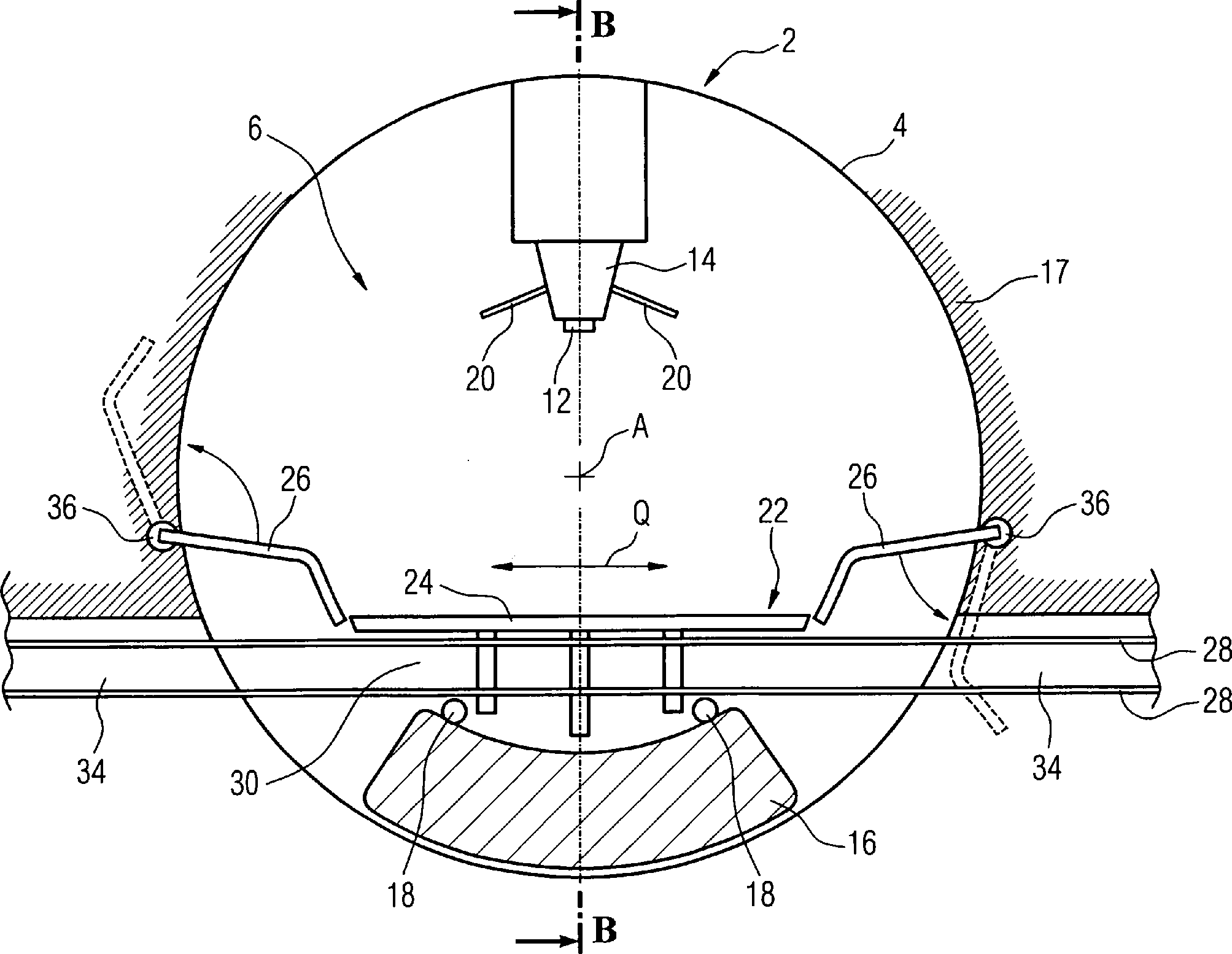
Eine Partikeltherapie-Anlage (2) umfasst eine um eine axiale Drehachse (A) rotierbare Gantry (4), die einen Bestrahlungsraum (6) mit einem zumindest eine bewegliche Platte (24) aufweisenden Boden (22) umschließt, wobei innerhalb des Bestrahlungsraums (6) ein Patiententisch (8) positionierbar ist. Um einen auf dem Patiententisch gelagerten Patienten auch von unten bestrahlen zu können, ist die Platte (24) in einer senkrecht zur Axialrichtung verlaufenden Querrichtung (Q) horizontal aus dem Bestrahlungsraum (6) verfahrbar.A Particle Therapy System (2) comprises one about an axial axis of rotation (A) rotatable gantry (4) having an irradiation space (6) with a enclosing at least one movable plate (24) having bottom (22), wherein within the irradiation room (6) a patient table (8) positionable is. To a patient stored on the patient table also by to be able to irradiate below the plate (24) is in a direction perpendicular to the axial direction Transverse direction (Q) horizontally from the irradiation space (6) movable.
Description
Die Erfindung betrifft eine Partikeltherapie-Anlage umfassend eine um eine axiale Drehachse rotierbare Gantry, die einen Bestrahlungsraum mit einem zumindest eine bewegliche Platte aufweisenden Boden umschließt, wobei innerhalb des Bestrahlungsraums ein Patiententisch positionierbar ist.The The invention relates to a particle therapy system comprising a an axial axis of rotation rotatable gantry containing an irradiation room encloses with a floor having at least one movable plate, wherein a patient table can be positioned within the irradiation room is.
Bei einer Partikeltherapie, insbesondere von Krebserkrankungen, wird in einem geeigneten Beschleuniger ein Partikelstrahl beispielweise aus Protonen oder Schwerionen erzeugt. Der Partikelstrahl wird in einem Strahlungskanal geführt und tritt über ein Austrittsfenster des Strahlungskanals in einen Bestrahlungsraum ein. In vielen Fällen ist wegen der aufwändigen Strahlungsführung lediglich ein ortsfestes Strahlaustrittsfenster vorgesehen. Bei einigen Anlagen ist jedoch eine drehbare Gantry mit einem Austrittsfenster vorgesehen. Wegen der aufwändigen Strahlungsführung ist die Gantry sehr großvolumig aufgebaut. Die Gantry umschließt einen etwa zylinderförmigen Bestrahlungsraum, in den ein Patiententisch hineingefahren wird. Für eine möglichst präzise Behandlung muss das zu bestrahlende Gewebe des Patienten möglichst genau im sogenannten Isozentrum der Anlage positioniert werden.at a particle therapy, especially of cancers, is in a suitable accelerator, a particle beam, for example generated from protons or heavy ions. The particle beam is in guided a radiation channel and enters Exit window of the radiation channel in an irradiation room one. In many cases is because of the elaborate radiation guidance only a fixed beam exit window provided. at However, some systems have a rotatable gantry with an exit window intended. Because of the elaborate radiation guidance the gantry is very large built up. The gantry encloses an approximately cylindrical Radiation room into which a patient table is moved. For one preferably precise Treatment must as far as possible the tissue to be irradiated of the patient be positioned exactly in the so-called isocenter of the plant.
Am Ende des Strahlungskanals sind in einer Bestrahlungseinheit unmittelbar vor dem Austrittsfenster üblicherweise mindestens ein Strahlendetektor sowie passive Strahlelemente angeordnet. Um den Patienten auch von unten bestrahlen zu können, ist die Gantry idealerweise um 360° um den Patienten rotierbar. Hierbei besteht das Problem, dass die Bestrahlungseinheit auch im Bereich unterhalb des Patienten rotierbar sein muss. Für diesen Zweck öffnet sich der Boden des Bestrahlungsraums, um den Durchtritt der Bestrahlungseinheit durch die Bodenelemente zu ermöglichen. Jedoch wird gleichzeitig ein Boden im Bestrahlungsraum benötigt, damit der Patient zugänglich ist, Wartungsarbeiten durchgeführt werden können und keine Absturzgefahr für das Bedienpersonal besteht.At the End of the radiation channel are directly in an irradiation unit usually in front of the exit window arranged at least one radiation detector and passive beam elements. In order to be able to irradiate the patient from below, the gantry is ideal around 360 ° around rotatable to the patient. Here, the problem is that the irradiation unit must also be rotatable in the area below the patient. For this Purpose opens the floor of the irradiation room to the passage of the irradiation unit to allow through the floor elements. However, at the same time a floor in the irradiation room is needed, so the patient is accessible is, maintenance can be done and no danger of falling for the operating staff exists.
In
der
Weitere
Ausführungsformen
des Bodens einer Gantry für
eine Partikeltherapie sind z.B. aus der Druckschrift
Der Erfindung liegt die Aufgabe zugrunde eine Partikeltherapie-Anlage mit einem einfachen und kompakten Aufbau anzugeben, bei der der Patient auch von unten bestrahlt werden kann.Of the Invention is the object of a particle therapy system with a simple and compact structure, in which the Patient can also be irradiated from below.
Die Aufgabe wird erfindungsgemäß gelöst durch eine Partikeltherapie-Anlage, umfassend eine um eine axiale Drehachse rotierbare Gantry, die einen Bestrahlungsraum mit einem zumindest eine bewegliche Platte aufweisenden Boden umschließt, in welchen Bestrahlungsraum ein Patiententisch positionierbar ist, wobei die Platte zum Ermöglichen eines Durchtritts einer Bestrahlungseinheit und/oder eines Gegengewichts in einer senkrecht zur Axialrichtung verlaufenden Querrichtung horizontal aus dem Bestrahlungsraum verfahrbar ist.The The object is achieved by a particle therapy system comprising one about an axial axis of rotation rotatable gantry, which has an irradiation room with an at least enclosing a movable plate having ground in which Radiation room is a patient table positionable, the Plate to enable a passage of an irradiation unit and / or a counterweight horizontally in a transverse direction perpendicular to the axial direction can be moved out of the irradiation room.
Das Verfahren einer oder mehrerer Platten in einer Querrichtung horizontal aus dem Bestrahlungsraum hat den Vorteil, dass die weggefahrenen Platten die Rotation der Bestrahlungseinheit der Gantry oder des der Bestrahlungseinheit gegenüberliegenden Gegengewichts nicht stören. Ein horizontales Verfahren der Platten ist technisch leicht zu realisieren, denn es ist eine einfache tragende Konstruktion ausreichend und der technische Aufwand zum Bewegen der Platten ist gering.The Method of one or more plates in a transverse direction horizontally from the irradiation room has the advantage that the weggefahrenen Plates the rotation of the irradiation unit of the gantry or the the irradiation unit opposite Do not disturb the counterweight. A horizontal process of the plates is technically easy to implement, because it is a simple structural design sufficient and the technical effort to move the plates is low.
Bei mehreren den Boden ausbildenden Platten werden immer nur diejenigen Platten entfernt, bei denen eine Kollision mit der Bestrahlungseinheit der Gantry droht, beispielsweise in einem Randbereich des Bodens. So bleibt der Boden im Bestrahlungs raum immer großflächig begehbar. Der Boden ist außerdem so ausgebildet, dass ein Hinausfahren einer oder mehrerer Platten keinerlei negative Auswirkungen auf die Steifigkeit des verbleibenden Bodens hat.at several plates forming the bottom are always just those Plates removed, where a collision with the irradiation unit the gantry threatens, for example in an edge area of the floor. So the floor in the irradiation room always remains accessible over a large area. The floor is as well designed so that a drive out one or more plates no negative impact on the stiffness of the remaining Bodens has.
Alternativ kann der Boden aus nur einer Platte bestehen, die in Abhängigkeit von der Position der Bestrahlungseinheit bzw. des Gegengewichts teilweise oder vollständig aus dem Bestrahlungsraum hinausgefahren wird. Diese Ausführungsvariante ist besonders einfach, da die Platte lediglich mit einer einfachen, linearen Bewegung seitlich verschoben wird. Die durch das Verschieben der Platte entstehenden Öffnungen im Boden werden in vielen Fallen durch die Bestrahlungseinheit und das Gegengewicht zumindest teilweise abgedeckt, wodurch die Absturzgefahr reduziert ist. Die Platte ist insbesondere derart gelagert, dass sie horizontal in entgegengesetzten Richtungen verschoben werden kann. Wenn eine Kollision mit der Platte von einer Seite droht, wird die Platte entsprechend derart in Richtung der entgegengesetzten Seite verfahren, dass die Kollision bei einer möglichst großen verbleibenden Bodenfläche vermieden wird.alternative The soil can consist of only one plate, depending on from the position of the irradiation unit or the counterweight partially or completely is moved out of the irradiation room. This variant is particularly simple, since the plate is simply a simple, linear movement is shifted laterally. The by moving the plate resulting openings in the ground are in many cases by the irradiation unit and the counterweight is at least partially covered, reducing the risk of falling is reduced. The plate is in particular mounted such that they are shifted horizontally in opposite directions can. If a collision with the plate threatens from one side, The plate is accordingly in the direction of the opposite Side procedure that avoids the collision with the largest possible remaining floor space becomes.
In vielen Fällen ist die Mantelfläche des etwa zylinderförmigen Bestrahlungsraums durch eine feste Raumwand gebildet, an der Komponenten der Gantry gelagert sind, beispielweise die Bestrahlungseinheit und das Gegengewicht. Daher sind vorteilhafterweise in der den Bestrahlungsraum seitlich begrenzenden und sich axial erstreckenden Festwand Aufnahmen für die zumindest eine Platte vorgesehen. Diese Aufnahmen sind insbesondere beidseitig des Bestrahlungsraums ausgebildet, wodurch eine besonders hohe Bewegungsfreiheit der einen oder mehreren Platten gewährleistet ist. Die Aufnahmen sind etwa auf der Höhe des Bodens angeordnet und an die Größe und Form der Platten angepasst, so dass alle den Boden bildenden Platten gleichzeitig außerhalb des Bestrahlungsraums gelagert werden können.In many cases, the lateral surface of the approximately cylindrical irradiation space by a fes te room wall formed on the components of the gantry are stored, for example, the irradiation unit and the counterweight. Therefore, recordings for the at least one plate are advantageously provided in the irradiation space laterally delimiting and extending axially fixed wall. These recordings are in particular formed on both sides of the irradiation space, whereby a particularly high freedom of movement of the one or more plates is ensured. The recordings are arranged approximately at the level of the floor and adapted to the size and shape of the plates, so that all the plates forming the bottom can be stored simultaneously outside the irradiation room.
Weiter bevorzugt ist die Platte an einem an den Bestrahlungsraum stirnseitig angrenzenden Festboden beweglich gelagert. Der Festboden ist ein besonders festes Fundament, auf dem die tragende Konstruktion und die Bewegungsmechanik der Platten angebracht sind. Er stellt eine vom Bestrahlungsraum und von der Gantry unabhängige Konstruktion dar, ist mit diesen also nicht verbunden. Dies erlaubt einen besonders einfachen Aufbau des Bestrahlungsraums, wobei eine Rückwand des Bestrahlungsraums, die der Stirnseite des Bestrahlungsraums gegenüberliegt, mitdreht, der Boden jedoch stehen bleibt.Further Preferably, the plate is at one end to the irradiation space adjacent fixed floor movably mounted. The hard floor is a special one firm foundation on which the supporting structure and the movement mechanics the plates are attached. He puts one from the irradiation room and independent from the gantry Construction, is therefore not associated with these. This allows one Particularly simple construction of the irradiation room, wherein a rear wall of the Irradiation space, which is opposite the front of the irradiation room, rotates, but the ground stops.
Gemäß einer bevorzugten Ausführungsform ist auf einer dem Bestrahlungsraum zugewandten Stirnseite des Festbodens ein sich in Querrichtung erstreckendes Führungselement zum Lagern und Verfahren der Platte vorgesehen. Das Führungselement ist insbesondere derart lang ausgebildet, dass die zumindest eine Platte völlig außerhalb des Bestrahlungsraums verfahren werden kann. Dabei ist das Führungselement derart gestaltet, dass die Stabilität des Festbodens nicht beeinträchtigt ist. Die Anordnung des Führungselements auf der Stirnseite hat den Vorteil, dass auf dieser Seite des Festbodens die Trag- und Bewegungsmechanik der Platten geschützt vor unabsichtlichen Beschädigungen ist und ein einwandfreier Betrieb gewährleistet ist.According to one preferred embodiment on an irradiation room facing front side of the hard floor a transversely extending guide member for storage and method the plate provided. The guide element is in particular designed so long that the at least one Plate completely outside the irradiation room can be moved. Here is the guide element designed so that the stability of the floor is not impaired. The arrangement of the guide element on the front has the advantage of being on this side of the hard floor the supporting and movement mechanics of the plates protected from unintentional damage is and a perfect operation is guaranteed.
Vorteilhafterweise sind eine zentrale Grundplatte und zwei Seitenplatten vorgesehen, wobei die Breite der Seitenplatten jeweils etwa zwischen 15% bis 25% der Gesamtbreite des Bodens beträgt. Hierbei können die Seitenplatten eine eingeschränkte Tragfähigkeit aufweisen, so dass sie hauptsächlich als Absturzsicherung dienen. Besonders vorteilhaft ist diese Ausführung, wenn die Bestrahlungseinheit und das Gegengewicht dem Boden näher kommen, ohne vollständig ein- bzw. auftauchen zu müssen. Dann werden lediglich die Seitenplatten weggeschoben, die Grundplatte bleibt unbewegt und bietet ausreichende Tragfähigkeit.advantageously, are a central base plate and two side plates provided the width of the side plates each about between 15% to 25% of the total width of the floor. Here, the Side plates have a limited load capacity so they mainly as Fall protection serve. Particularly advantageous is this embodiment, if the irradiation unit and the counterweight come closer to the ground, without Completely have to appear or emerge. Then only the side plates are pushed away, the base plate remains unmoved and provides sufficient carrying capacity.
Nach einer vorteilhaften Variante sind die Seitenplatten schwenkbar gelagert. Durch diese Variante ist der in Querrichtung benötigte Platz reduziert, da nur die Grundplatte horizontal hinausgefahren werden muss.To In an advantageous variant, the side plates are pivotally mounted. By this variant, the space required in the transverse direction is reduced because only The base plate must be moved out horizontally.
Nach einer weiteren vorteilhaften Variante sind die Seitenplatten derart gelagert, dass sie bezüglich des Bodens sowohl nach oben als auch nach unten schwenkbar sind. Hierbei wird berücksichtigt von welcher Richtung sich die Bestrahlungseinheit und das Gegengewicht annähern und die Seitenplatten werden entsprechend geschwenkt, wodurch eine Optimierung des Bewegungsablaufs der Platten erzielt ist. Wenn sich die im Uhrzeigersinn bewegliche Bestrahlungseinheit z.B. von oben der auf der Stirnseite rechts angeordneten Seitenplatte annähert, wird die letztere entsprechend nach unten geklappt. Gleichzeitig wird die linke Seitenplatte nach oben geschwenkt, um Platz für das der Bestrahlungseinheit gegenüberliegende Gegengewicht zu schaffen.To In a further advantageous variant, the side plates are such stored that they respect of the floor are pivotable both upwards and downwards. This is taken into account by which direction the irradiation unit and the counterweight approach and the side plates are pivoted accordingly, creating an optimization the movement sequence of the plates is achieved. When the clockwise movable irradiation unit e.g. from the top of the front approaching the right side plate, the latter is accordingly worked down. At the same time, the left side plate goes down panned up to make room for the counterweight opposite the irradiation unit create.
Zweckdienlicherweise ist die Schwenkachse der Seitenplatten oberhalb der Grundplatte angeordnet. Dadurch, dass die Schwenkachsen etwas beabstandet von den Aufnahmen für die Grundplatte positioniert sind, steht ausreichend Platz zur Verfügung zur Ausbildung der Aufnahmen.Conveniently, is the pivot axis of the side plates above the base plate arranged. Due to the fact that the pivot axes are slightly separated from the recordings for the base plate are positioned, there is sufficient space available for Training the recordings.
Bevorzugt weist die zumindest eine Platte Rollen zum Lagern auf dem Führungselement auf. Durch die Rollen kann die Platte einfach hin- und herverfahren werden, wobei die Reibungskräfte minimal sind. Die Bewegungsbahn der Rollen wird hierbei durch das Führungselement vorgegeben. Da die Platte nur einseitig gestützt ist, wirkt auf sie ein großes Drehmoment. Die Achsen, an denen die Rollen gelagert sind, und die Rollen selbst müssen die Belastung der Platte durch das eigene Gewicht und weitere Lasten aufnehmen können. Deshalb sind die Achsen und die Rollen sehr solide gestaltet, so dass sie das Gewicht der Platte sowie das Gewicht mindestens einer auf der Platte stehenden Person aufnehmen können. Hierbei ist eine hohe Anzahl an Rädern bzw. Achsen vorteilhaft, damit sich die Last auf die einzelnen Achsen verteilen kann.Prefers the at least one plate has rollers for storage on the guide element on. The rollers make it easy to move the plate back and forth be, with the frictional forces are minimal. The trajectory of the rollers is here by the guide element specified. Since the plate is only supported on one side, it acts on them great Torque. The axes on which the rollers are mounted, and the Roll yourself the load on the plate due to its own weight and other loads be able to record. That's why the axles and the rollers are very solid, so that they are the weight of the plate as well as the weight of at least one can record on the plate standing person. This is a high Number of wheels or axes advantageous, so that the load on the individual axes can distribute.
Der Boden weist vorzugsweise mehrere horizontal verfahrbare Platten auf, die seitlich außerhalb des Bestrahlungsraums übereinander positionierbar sind. Hierbei kann Platz gespart werden, indem die zuerst hinausgefahrenen Platten höher oder tiefer in einer Parkposition abgelegt werden, so dass die nachfolgenden Platten darunter bzw. darüber geparkt werden können. Durch diese schichtweise Anordnung der weggefahrenen Platten können die Abmessungen der Aufnahmen in Querrichtung besonders klein gehalten werden. Möglich ist auch, dass unterschiedliche Führungselemente für die unterschiedlichen Platten vorgesehen sind, welche Führungselemente in der Höhe leicht zueinander versetzt sind, allerdings so, dass keine wesentlichen Spalte zwischen den Platten des Bodens entsehen. Zum Beispiel, wenn der Boden aus einer Grundplatte und zwei Seitenplatten besteht, kann ein längeres zentrales Führungselement für die Grundplatte vorgesehen und in der Höhe etwas versetzt zwei seitliche Führungselemente für die Seitenplatten angeordnet sein.The floor preferably has a plurality of horizontally movable plates, which can be positioned laterally outside of the irradiation space one above the other. This space can be saved by the first passed out plates are stored higher or lower in a parking position, so that the subsequent plates can be parked underneath or above. By this layered arrangement of the weggefahrenen plates, the dimensions of the images in the transverse direction can be kept very small. It is also possible that different guide elements are provided for the different plates, which Füh are slightly offset from each other in height, but so that no significant gaps between the plates of the soil entsehen. For example, if the floor consists of a base plate and two side plates, a longer central guide element may be provided for the base plate and arranged slightly offset in height two lateral guide elements for the side plates.
Gemäß einer bevorzugten Weiterbildung zweigt sich das Führungselement im Bereich seitlich außerhalb des Bestrahlungsraums in zwei übereinander verlaufende Teilarme auf. Insbesondere verläuft einer der Teilarme horizontal als eine Verlängerung des Führungselements, so dass einige der Platten, insbesondere die etwas breiteren Platten, wenn die Platten unterschiedlich breit ausgestaltet sind, problemlos hin und her horizontal verfahren werden können. Bei dieser Weiterbildung werden die weggefahrenen Platten ebenfalls übereinander geparkt, wodurch wenig Platz in Querrichtung abseits des Bestrahlungsraums belegt wird.According to one preferred embodiment, the guide element branches in the area laterally outside of the irradiation room in two on top of each other extending partial arms on. In particular, one of the arms extends horizontally as an extension the guide element, so some of the plates, especially the slightly wider plates, if the plates are designed differently wide, easily can be moved back and forth horizontally. In this training the weggefahrenen plates are also parked on top of each other, which little space in the transverse direction away from the irradiation room occupied becomes.
Um eine erhöhte Steifigkeit des Bodens zu gewährleisten, ist die zumindest eine Platte bevorzugt zur Stirnseite des Festbodens L-förmig abgewinkelt und es sind mehrere Führungselemente in Radialrichtung vorgesehen. Insbesondere ist der ra dial nach unten erstreckende Teil der abgewinkelten Platte nach Art eines Stützwinkels geformt, der sich über die Führungselemente an mehreren Stellen des Festbodens abstützt. Dabei erstreckt sich der Stützwinkel in Radialrichtung nur so weit nach unten, dass keine Kollisionsgefahr mit dem Gegengewicht vorliegt.Around an increased To ensure rigidity of the soil is the at least one plate preferably to the front of the hard floor L-shaped angled and there are several guide elements in the radial direction intended. In particular, the ra dial is downwardly extending Part of the angled plate formed in the manner of a support bracket, which extends over the guide elements supported at several points of the ground. In this case, the support angle extends in the radial direction only so far down that no risk of collision is present with the counterweight.
Vorteilhafterweise ist das Führungselement eine Linearführung, insbesondere eine Führungsschiene oder Führungsrille. Die Linearführung erlaubt eine translatorische Bewegung der Platte entlang einer definierten Bewegungsbahn, die besonders günstig für das Hin- und Herschieben der Platten ist.advantageously, is the guide element one Linear guide, in particular a guide rail or guide groove. The linear guide allows a translatory movement of the plate along a defined Movement path, the most favorable for the Shuffling the plates is.
Häufig sind in einer solchen Partikeltherapie-Anlage auch Bildgebungssysteme integriert, wie etwa eine Röntgenröhre und ein gegenüberliegender Röntgendetektor. Es ist besonders günstig den Röntgendetektor und die Röntgenröhre auf der Bestrahlungseinheit bzw. dem Gegengewicht zu montieren, denn dadurch rotiert das Bildgebungssystem mit der Gantry und mittels einer Gantryumdrehung lässt sich einfach ein Volumenbild eines erkrankten Gewebes des Patienten erzeugen. Damit die Platten bei einem im Bestrahlungsraum vorhandenen Boden die Bildgebung nicht stören, ist es besonders vorteilhaft, dass die Platten einen röntgentransparenten Bereich, z.B. aus einem kohlefaserverstärkten Kunststoff, umfassen. Der röntgentransparente Bereich weist beispielweise die Form eines sich in Querrichtung erstreckenden Streifens auf.Frequently in such a particle therapy facility also imaging systems integrated, such as an x-ray tube and an opposite X-ray detector. It is very cheap the x-ray detector and the x-ray tube the irradiation unit or the counterweight to assemble, because As a result, the imaging system rotates with the gantry and by means of a gantry turn leaves Just a volume image of a diseased tissue of the patient produce. So that the plates in an existing in the irradiation room Soil does not disturb the imaging, It is particularly advantageous that the plates have an X-ray transparent Range, e.g. from a carbon fiber reinforced plastic. The X-ray transparent Area has, for example, the shape of a transversely extending strip on.
Zum Positionieren des Patiententisches innerhalb des Bestrahlungsraums ist bevorzugt ein auf dem Festboden befestigter Roboter vorgesehen. Dadurch kann der Patiententisch in den von der Gantry umschlossenen Bestrahlungsraum hineingefahren und gehalten werden, ohne dass der Patiententisch Kontakt mit dem Boden hat. Somit wird eine besonders hohe Stabilität des Patiententisches gewährt, da seine Lage im Bestrahlungsraum unabhängig von der jeweiligen Position und Anordnung der Platten ist.To the Positioning the patient table within the irradiation room Preferably, a fixed on the floor robot is provided. This allows the patient table to be enclosed in the gantry Radiation space are moved in and kept without the Patient table has contact with the ground. Thus, a special high stability granted the patient table, because its location in the irradiation room regardless of the position and arrangement of the plates is.
Ausführungsbeispiele der Erfindung werden anhand einer Zeichnung näher erläutert. Hierin zeigen schematisch:embodiments The invention will be explained in more detail with reference to a drawing. Herein schematically show:
Gleiche Bezugszeichen haben in den Figuren die gleiche Bedeutung.Same Reference numerals have the same meaning in the figures.
In
Zur
Bildgebung eines erkrankten Gewebes des Patienten ist ein in der
Gantry
Der
Bestrahlungsraum
Um
die Grundplatte
Beidseitig
des Bestrahlungsraums
Auf
beiden Seiten des Bestrahlungsraums
Die
Seitenplatten
Die
Führungsschienen
In
Aus
Der
Bestrahlungsraum
Wie
aus der Schnittsdarstellung ersichtlich ist, ist die Grundplatte
Die
Grundplatte
Zur
Durchführung
der Therapie wird der Patient
Aufgrund
des relativ großen
Volumens der Bestrahlungseinheit
Eine
zweite beispielhafte Ausführungsvariante
der Partikeltherapieanlage
Auf
beiden Seiten des Bestrahlungsraums
Um
eine Positionierung der Platten
Wie
die Platten
Eine
dritte Ausführungsvariante
der Partikeltherapieanlage
Dank
dem hier beschriebenen Aufbau und der Art des Verfahrens der zumindest
einen Platte
Claims (15)
Priority Applications (2)
| Application Number | Priority Date | Filing Date | Title |
|---|---|---|---|
| DE102006026212A DE102006026212B3 (en) | 2006-06-06 | 2006-06-06 | Particle therapy system with at least one movable base plate |
| US11/809,645 US20080029706A1 (en) | 2006-06-06 | 2007-06-01 | Particle therapy device |
Applications Claiming Priority (1)
| Application Number | Priority Date | Filing Date | Title |
|---|---|---|---|
| DE102006026212A DE102006026212B3 (en) | 2006-06-06 | 2006-06-06 | Particle therapy system with at least one movable base plate |
Publications (1)
| Publication Number | Publication Date |
|---|---|
| DE102006026212B3 true DE102006026212B3 (en) | 2008-02-21 |
Family
ID=38955127
Family Applications (1)
| Application Number | Title | Priority Date | Filing Date |
|---|---|---|---|
| DE102006026212A Expired - Fee Related DE102006026212B3 (en) | 2006-06-06 | 2006-06-06 | Particle therapy system with at least one movable base plate |
Country Status (2)
| Country | Link |
|---|---|
| US (1) | US20080029706A1 (en) |
| DE (1) | DE102006026212B3 (en) |
Families Citing this family (13)
| Publication number | Priority date | Publication date | Assignee | Title |
|---|---|---|---|---|
| US20140066755A1 (en) * | 2012-08-29 | 2014-03-06 | ProNova Solutions, LLC | Simultaneous Imaging and Particle Therapy Treatment system and Method |
| CN104797295B (en) * | 2012-10-26 | 2017-03-15 | 普罗诺瓦解决方案有限责任公司 | movable floor for proton therapy |
| EP3049151B1 (en) | 2013-09-27 | 2019-12-25 | Mevion Medical Systems, Inc. | Particle beam scanning |
| US10675487B2 (en) | 2013-12-20 | 2020-06-09 | Mevion Medical Systems, Inc. | Energy degrader enabling high-speed energy switching |
| US9962560B2 (en) | 2013-12-20 | 2018-05-08 | Mevion Medical Systems, Inc. | Collimator and energy degrader |
| US9661736B2 (en) | 2014-02-20 | 2017-05-23 | Mevion Medical Systems, Inc. | Scanning system for a particle therapy system |
| JP6523076B2 (en) * | 2015-06-30 | 2019-05-29 | 株式会社日立製作所 | Particle therapy system |
| US10786689B2 (en) | 2015-11-10 | 2020-09-29 | Mevion Medical Systems, Inc. | Adaptive aperture |
| US10925147B2 (en) | 2016-07-08 | 2021-02-16 | Mevion Medical Systems, Inc. | Treatment planning |
| US11103730B2 (en) | 2017-02-23 | 2021-08-31 | Mevion Medical Systems, Inc. | Automated treatment in particle therapy |
| US10426977B2 (en) * | 2017-06-30 | 2019-10-01 | Varian Medical Systems Particle Therapy Gmbh. | Moving floor for radiotherapy system with cantilever gantry assembly |
| JP6940676B2 (en) | 2017-06-30 | 2021-09-29 | メビオン・メディカル・システムズ・インコーポレーテッド | Configurable collimator controlled using a linear motor |
| EP3934751B1 (en) | 2019-03-08 | 2024-07-17 | Mevion Medical Systems, Inc. | Collimator and energy degrader for a particle therapy system |
Citations (4)
| Publication number | Priority date | Publication date | Assignee | Title |
|---|---|---|---|---|
| US6814694B1 (en) * | 1999-06-25 | 2004-11-09 | Paul Scherrer Institut | Device for carrying out proton therapy |
| US20050161618A1 (en) * | 2002-09-18 | 2005-07-28 | Paul Scherrer Institut | Arrangement for performing proton therapy |
| WO2006076545A2 (en) * | 2005-01-14 | 2006-07-20 | Indiana University Research And Technology Corporation | Automatic retractable floor system for a rotating gantry |
| JP2006192297A (en) * | 2006-03-31 | 2006-07-27 | Mitsubishi Electric Corp | Rotating irradiation device |
Family Cites Families (3)
| Publication number | Priority date | Publication date | Assignee | Title |
|---|---|---|---|---|
| US5096530A (en) * | 1990-06-28 | 1992-03-17 | 3D Systems, Inc. | Resin film recoating method and apparatus |
| DE60208879T2 (en) * | 2001-03-28 | 2006-11-02 | Showa Denko K.K. | PLATE MEMBER STACKING DEVICE, METHOD FOR STACKING PLATE MEMBERS AND STACKED PLATE MEMBERS |
| US7412733B2 (en) * | 2005-03-08 | 2008-08-19 | Dorsch, Inc. | Retractable cover arrangement for hot tubs and the like |
-
2006
- 2006-06-06 DE DE102006026212A patent/DE102006026212B3/en not_active Expired - Fee Related
-
2007
- 2007-06-01 US US11/809,645 patent/US20080029706A1/en not_active Abandoned
Patent Citations (4)
| Publication number | Priority date | Publication date | Assignee | Title |
|---|---|---|---|---|
| US6814694B1 (en) * | 1999-06-25 | 2004-11-09 | Paul Scherrer Institut | Device for carrying out proton therapy |
| US20050161618A1 (en) * | 2002-09-18 | 2005-07-28 | Paul Scherrer Institut | Arrangement for performing proton therapy |
| WO2006076545A2 (en) * | 2005-01-14 | 2006-07-20 | Indiana University Research And Technology Corporation | Automatic retractable floor system for a rotating gantry |
| JP2006192297A (en) * | 2006-03-31 | 2006-07-27 | Mitsubishi Electric Corp | Rotating irradiation device |
Non-Patent Citations (4)
| Title |
|---|
| JP 2006-192 297 A (ältere Anmeldung) |
| U. Kopf et al.: "The gantry irradiation room at the Heidelberg ion therapy facility", Jahresbe- richt der GSI Darmstadt 2003, GSI-2004-1 (2004), S. 183 |
| U. Kopf et al.: "The gantry irradiation room at the Heidelberg ion therapy facility", Jahresbericht der GSI Darmstadt 2003, GSI-2004-1 (2004), S. 183 * |
| WO 2006/076 545 A2 (ältere Anmeldung) |
Also Published As
| Publication number | Publication date |
|---|---|
| US20080029706A1 (en) | 2008-02-07 |
Similar Documents
| Publication | Publication Date | Title |
|---|---|---|
| EP0992217B1 (en) | Operating table system | |
| DE102007003878B4 (en) | Particle therapy system with movable floor segment | |
| DE102007029192B3 (en) | Gantry with alternative space for a particle therapy facility | |
| DE10241178B4 (en) | Isokinetic gantry arrangement for the isocentric guidance of a particle beam and method for its design | |
| DE102006026212B3 (en) | Particle therapy system with at least one movable base plate | |
| DE10196489B3 (en) | Operating table, in particular for surgical interventions | |
| EP1539299B1 (en) | System for performing proton therapy | |
| DE19955119B4 (en) | Patient support plate for a medical examination table | |
| EP2825098B1 (en) | Detector assembly for recording x-ray images of an object to be imaged | |
| DE19905823C1 (en) | Collimator for high energy radiation, e.g. for the treatment of tumors, comprises numerous opposing scree sections made of radiation absorbing material | |
| DE102007011399A1 (en) | Particle therapy facility | |
| DE102015201565B4 (en) | Order picking device in the form of a turntable | |
| DE102006002908B3 (en) | Particle therapy system for treating cancer disease, has rotatable gantry enclosing radiation area with base, where base has movable segments displaceable under adjacent base region, and base is limited at irradiation area | |
| EP0371303A1 (en) | Radiation therapy apparatus | |
| DE2617974A1 (en) | DEVICE FOR POSITIONING THE BODY OF A PATIENT IN A RADIATION DEVICE | |
| DE2749910A1 (en) | X-RAY FILM RECORDING DEVICE | |
| DE102016214678A1 (en) | Mobile grid detector arrangement | |
| DE102016210497A1 (en) | Patient positioning device and medical workstation | |
| DE102019203882B3 (en) | Patient positioning device and medical imaging device | |
| DE69806157T2 (en) | DEVICE FOR TRAINING HORSES | |
| DE102008057145A1 (en) | Patient transport unit and method for transporting a patient | |
| EP2883567A1 (en) | Patient positioning device and method for positioning a patient on an irradiation device by means of a patient positioning device | |
| DE60222749T2 (en) | MEDICAL C ARC SET WITH REINFORCED TREAD ROOFS | |
| EP4327747A1 (en) | Computer-implemented method for operating an x-ray device and x-ray device | |
| DE202012013203U1 (en) | X-ray table and X-ray workplace with it |
Legal Events
| Date | Code | Title | Description |
|---|---|---|---|
| 8364 | No opposition during term of opposition | ||
| R119 | Application deemed withdrawn, or ip right lapsed, due to non-payment of renewal fee |
Effective date: 20120103 |