DE102006002751B4 - Swing door operator with cam - Google Patents
Swing door operator with cam Download PDFInfo
- Publication number
- DE102006002751B4 DE102006002751B4 DE102006002751A DE102006002751A DE102006002751B4 DE 102006002751 B4 DE102006002751 B4 DE 102006002751B4 DE 102006002751 A DE102006002751 A DE 102006002751A DE 102006002751 A DE102006002751 A DE 102006002751A DE 102006002751 B4 DE102006002751 B4 DE 102006002751B4
- Authority
- DE
- Germany
- Prior art keywords
- cam
- output shaft
- swing door
- drive
- curve
- Prior art date
- Legal status (The legal status is an assumption and is not a legal conclusion. Google has not performed a legal analysis and makes no representation as to the accuracy of the status listed.)
- Expired - Fee Related
Links
Images


Classifications
-
- E—FIXED CONSTRUCTIONS
- E05—LOCKS; KEYS; WINDOW OR DOOR FITTINGS; SAFES
- E05F—DEVICES FOR MOVING WINGS INTO OPEN OR CLOSED POSITION; CHECKS FOR WINGS; WING FITTINGS NOT OTHERWISE PROVIDED FOR, CONCERNED WITH THE FUNCTIONING OF THE WING
- E05F3/00—Closers or openers with braking devices, e.g. checks; Construction of pneumatic or liquid braking devices
- E05F3/04—Closers or openers with braking devices, e.g. checks; Construction of pneumatic or liquid braking devices with liquid piston brakes
- E05F3/10—Closers or openers with braking devices, e.g. checks; Construction of pneumatic or liquid braking devices with liquid piston brakes with a spring, other than a torsion spring, and a piston, the axes of which are the same or lie in the same direction
- E05F3/104—Closers or openers with braking devices, e.g. checks; Construction of pneumatic or liquid braking devices with liquid piston brakes with a spring, other than a torsion spring, and a piston, the axes of which are the same or lie in the same direction with cam-and-slide transmission between driving shaft and piston within the closer housing
-
- E—FIXED CONSTRUCTIONS
- E05—LOCKS; KEYS; WINDOW OR DOOR FITTINGS; SAFES
- E05F—DEVICES FOR MOVING WINGS INTO OPEN OR CLOSED POSITION; CHECKS FOR WINGS; WING FITTINGS NOT OTHERWISE PROVIDED FOR, CONCERNED WITH THE FUNCTIONING OF THE WING
- E05F15/00—Power-operated mechanisms for wings
- E05F15/60—Power-operated mechanisms for wings using electrical actuators
- E05F15/603—Power-operated mechanisms for wings using electrical actuators using rotary electromotors
- E05F15/611—Power-operated mechanisms for wings using electrical actuators using rotary electromotors for swinging wings
- E05F15/63—Power-operated mechanisms for wings using electrical actuators using rotary electromotors for swinging wings operated by swinging arms
-
- E—FIXED CONSTRUCTIONS
- E05—LOCKS; KEYS; WINDOW OR DOOR FITTINGS; SAFES
- E05Y—INDEXING SCHEME ASSOCIATED WITH SUBCLASSES E05D AND E05F, RELATING TO CONSTRUCTION ELEMENTS, ELECTRIC CONTROL, POWER SUPPLY, POWER SIGNAL OR TRANSMISSION, USER INTERFACES, MOUNTING OR COUPLING, DETAILS, ACCESSORIES, AUXILIARY OPERATIONS NOT OTHERWISE PROVIDED FOR, APPLICATION THEREOF
- E05Y2201/00—Constructional elements; Accessories therefor
- E05Y2201/40—Motors; Magnets; Springs; Weights; Accessories therefor
- E05Y2201/499—Spring tensioners; Tension sensors
-
- E—FIXED CONSTRUCTIONS
- E05—LOCKS; KEYS; WINDOW OR DOOR FITTINGS; SAFES
- E05Y—INDEXING SCHEME ASSOCIATED WITH SUBCLASSES E05D AND E05F, RELATING TO CONSTRUCTION ELEMENTS, ELECTRIC CONTROL, POWER SUPPLY, POWER SIGNAL OR TRANSMISSION, USER INTERFACES, MOUNTING OR COUPLING, DETAILS, ACCESSORIES, AUXILIARY OPERATIONS NOT OTHERWISE PROVIDED FOR, APPLICATION THEREOF
- E05Y2201/00—Constructional elements; Accessories therefor
- E05Y2201/60—Suspension or transmission members; Accessories therefor
- E05Y2201/622—Suspension or transmission members elements
- E05Y2201/638—Cams; Ramps
-
- E—FIXED CONSTRUCTIONS
- E05—LOCKS; KEYS; WINDOW OR DOOR FITTINGS; SAFES
- E05Y—INDEXING SCHEME ASSOCIATED WITH SUBCLASSES E05D AND E05F, RELATING TO CONSTRUCTION ELEMENTS, ELECTRIC CONTROL, POWER SUPPLY, POWER SIGNAL OR TRANSMISSION, USER INTERFACES, MOUNTING OR COUPLING, DETAILS, ACCESSORIES, AUXILIARY OPERATIONS NOT OTHERWISE PROVIDED FOR, APPLICATION THEREOF
- E05Y2600/00—Mounting or coupling arrangements for elements provided for in this subclass
- E05Y2600/10—Adjustable
- E05Y2600/30—Adjustment motion
- E05Y2600/32—Rotary motion
- E05Y2600/324—Rotary motion around a vertical axis
-
- E—FIXED CONSTRUCTIONS
- E05—LOCKS; KEYS; WINDOW OR DOOR FITTINGS; SAFES
- E05Y—INDEXING SCHEME ASSOCIATED WITH SUBCLASSES E05D AND E05F, RELATING TO CONSTRUCTION ELEMENTS, ELECTRIC CONTROL, POWER SUPPLY, POWER SIGNAL OR TRANSMISSION, USER INTERFACES, MOUNTING OR COUPLING, DETAILS, ACCESSORIES, AUXILIARY OPERATIONS NOT OTHERWISE PROVIDED FOR, APPLICATION THEREOF
- E05Y2600/00—Mounting or coupling arrangements for elements provided for in this subclass
- E05Y2600/50—Mounting methods; Positioning
- E05Y2600/56—Positioning, e.g. re-positioning, or pre-mounting
- E05Y2600/58—Positioning, e.g. re-positioning, or pre-mounting by using indicators or markings, e.g. scales
-
- E—FIXED CONSTRUCTIONS
- E05—LOCKS; KEYS; WINDOW OR DOOR FITTINGS; SAFES
- E05Y—INDEXING SCHEME ASSOCIATED WITH SUBCLASSES E05D AND E05F, RELATING TO CONSTRUCTION ELEMENTS, ELECTRIC CONTROL, POWER SUPPLY, POWER SIGNAL OR TRANSMISSION, USER INTERFACES, MOUNTING OR COUPLING, DETAILS, ACCESSORIES, AUXILIARY OPERATIONS NOT OTHERWISE PROVIDED FOR, APPLICATION THEREOF
- E05Y2800/00—Details, accessories and auxiliary operations not otherwise provided for
- E05Y2800/15—Applicability
- E05Y2800/17—Universally applicable
-
- E—FIXED CONSTRUCTIONS
- E05—LOCKS; KEYS; WINDOW OR DOOR FITTINGS; SAFES
- E05Y—INDEXING SCHEME ASSOCIATED WITH SUBCLASSES E05D AND E05F, RELATING TO CONSTRUCTION ELEMENTS, ELECTRIC CONTROL, POWER SUPPLY, POWER SIGNAL OR TRANSMISSION, USER INTERFACES, MOUNTING OR COUPLING, DETAILS, ACCESSORIES, AUXILIARY OPERATIONS NOT OTHERWISE PROVIDED FOR, APPLICATION THEREOF
- E05Y2900/00—Application of doors, windows, wings or fittings thereof
- E05Y2900/10—Application of doors, windows, wings or fittings thereof for buildings or parts thereof
- E05Y2900/13—Type of wing
- E05Y2900/132—Doors
Landscapes
- Power-Operated Mechanisms For Wings (AREA)
Abstract
Drehflügeltürantrieb mit Kurvenscheibe (20) zum Öffnen und Schließen einer Tür oder dergleichen, welcher folgende Merkmale aufweist: – eine motorische Antriebseinheit (5); – eine Abtriebswelle (19), die über mindestens eine Aufnahmebuchse (36) mindestens mittelbar über ein Gestänge mit Hebel (35; 37, 38) und Lagerbock (40) einen zu bewegenden Flügel einer Tür oder dergleichen antreibt; – die Antriebseinheit (5) weist mit der Abtriebswelle (19) eine Triebverbindung auf; – mindestens einen Kraftspeicher (28), welcher eine drehbar gelagerte Rolle (23) über ein mit dem Kraftspeicher (28) verbundenes und mit einer Rollenachse (24) fest verbundenes Druckstück (25) auf die Umfangsfläche einer Ablaufkurve (47) mindestens einer Kurvenscheibe (20) presst, und – die mindestens eine Kurvenscheibe (20) ist drehfest mit der Abtriebswelle (19) verbunden, wobei verschiedene Winkelbereiche der Ablaufkurve (47) der mindestens einen Kurvenscheibe (20) für ziehende oder drückende Gestänge (35, 37, 38, 40) genutzt werden, dadurch gekennzeichnet, dass sowohl...Swing door drive with cam (20) for opening and closing a door or the like, which has the following features: - a motorized drive unit (5); - An output shaft (19) which drives a leaf to be moved of a door or the like via at least one receiving bushing (36) at least indirectly via a linkage with lever (35; 37, 38) and bearing block (40); - The drive unit (5) has a drive connection with the output shaft (19); - At least one energy storage device (28), which a rotatably mounted roller (23) via a pressure piece (25) connected to the energy storage device (28) and firmly connected to a roller axis (24) on the circumferential surface of a sequence curve (47) of at least one cam ( 20) presses, and - the at least one cam (20) is non-rotatably connected to the output shaft (19), with different angular ranges of the sequence curve (47) of the at least one cam (20) for pulling or pushing rods (35, 37, 38, 40), characterized in that both ...
Description
Gegenstand der Erfindung ist ein Drehflügeltürantrieb mit Kurvenscheibe nach dem Oberbegriff des Patentanspruches 1.The invention relates to a swing door operator with cam according to the preamble of
Die Erfindung sieht hierbei einen Drehflügelantrieb mit einer Kurvenscheibe und Kraftspeicher vor. Diese Kurvenscheibe erzeugt ein ungleichmäßiges Schließ- bzw. Öffnungsdrehmoment in Gegenrichtung zum motorischen Antrieb. Damit soll sichergestellt werden, dass die Tür über ein an den Antrieb gekoppeltes Gestänge auch bei Stromausfall automatisch schließt bzw. öffnet.The invention in this case provides a rotary vane drive with a cam and energy storage. This cam generates an uneven closing or opening torque in the opposite direction to the motor drive. This is to ensure that the door automatically closes or opens via a linkage coupled to the drive even in the event of a power failure.
In der Technik sind solche Kurvenscheiben mit Kraftspeicher seit längerer Zeit bei Türschließern bekannt (namentlich bei Türschließern der Firma Dorma). Es existieren sicher auch zu Türantrieben umgebaute Türschließer (mit Motor ergänzt), insbesondere von Dorma.In the art, such cams with energy storage for a long time in door closers known (namely in door closers from Dorma). There are certainly door closers converted into door drives (with motor supplements), especially Dorma.
In der Druckschrift
Dies ist jedoch nachteilig, weil wegen der Benutzung von zwei Ablaufflächen ein vorteilhaft zu verwendender Absolutweggeber zur Erfassung der Türposition für den motorischen Betrieb einen doppelt so großen Verfahrwinkel abdecken muss, auch wenn keine Pendeltür angetrieben wird.However, this is disadvantageous because, because of the use of two drain surfaces, an absolute encoder to be used advantageously for detecting the door position for motor operation must cover twice the travel angle, even if no swing door is driven.
Bei der erfindungsgemäßen Konstruktion ist vorgesehen, das der Drehflügeltürantrieb beim Wechsel von einem ziehendem zu einem drückendem Gestänge wechselseitig um 180° drehbar ist und eine beidseitige Ankoppelungsmöglichkeit aufweist, wobei notwendige, unterschiedliche Übersetzungsverhältnisse der verschiedenen Gestängetypen (Gleitschiene/Normalgestänge) mittels Verschiebung einer Startposition auf gleicher Kurvenscheibe ausgebildet sind.In the construction according to the invention it is provided that the swing door drive when changing from a pulling to a pushing linkage mutually rotatable by 180 ° and has a bilateral Ankoppelungsmöglichkeit, where necessary, different ratios of the different boom types (slide / normal linkage) by shifting a start position on the same Cam are formed.
In einer bevorzugten Ausgestaltung der Erfindung wird der Aufbau des Gerätes wie folgt beschrieben:
Es sind 2 identische Kurvenscheiben mit federbelasteten Rollen eingebaut, die parallel arbeiten (ergibt kleinere und gleichmäßig verteilte Kräfte, die sehr fein eingestellt werden können, andererseits können die Vorspannkräfte der beiden Federn auch unabhängig voneinander eingestellt werden. Sie sind durch die Position eines Bolzens gut ablesbar. Der entscheidende Punkt ist, dass nur eine einzige, fixe Kurvenform für die verschiedenen üblichen Gestängearten benötigt wird, d. h. das Gerät in einer einzigen Ausführung hergestellt werden kann und damit die Forderungen aus den Normen erfüllt werden.In a preferred embodiment of the invention, the structure of the device is described as follows:
There are 2 identical cams with spring-loaded rollers that work in parallel (results in smaller and evenly distributed forces that can be adjusted very finely, on the other hand, the preload forces of the two springs can also be adjusted independently.) They are easily readable by the position of a bolt The key point is that only a single, fixed curve shape is needed for the different types of common linkage, ie the device can be manufactured in a single design and thus meet the requirements of the standards.
Die Abtriebswelle befindet sich in der Mitte des Gerätes und kann beidseitig angegriffen werden, dadurch wird die andere Drehrichtung durch umgekehrte Montage des Gerätes erzielt, ohne dass sich die geräteinterne Drehrichtung oder optisch etwas ändert.The output shaft is located in the middle of the device and can be attacked on both sides, thereby the other direction of rotation is achieved by reverse assembly of the device, without changing the device's internal direction of rotation or visually something.
Der gewünschte Effekt der Kurvenscheibe generell ist das Erzielen einer großen Zuhaltekraft auch mit dem Hebel mit Gleitschiene, so wie man es mit einem Normalgestänge erreicht und gleichzeitig den Effekt zu eliminieren, dass die höchste Federkraft, die dafür sorgen soll, dass sich die Tür bei einem Stromausfall in die definierte Endlage bewegt (im Normalfall die Türe schließt), den Motor nicht so stark belastet (kritisch bei Daueröffnung). Neu ist bei diesem Gerät die Überlegung die verschiedenen Bereiche der identischen Kurve für die verschiedenen Gestänge zu nutzen.The desired effect of the cam generally is to achieve a large locking force even with the lever with slide rail, just as you can achieve with a normal rod and at the same time eliminate the effect that the highest spring force, which is to ensure that the door at a Power failure in the defined end position moves (normally the door closes), the engine is not so heavily loaded (critical for permanent opening). A new feature of this device is the idea to use the different sections of the identical curve for the different linkages.
Die Erfindung nimmt bewusst in Kauf, dass mit der gegebenen technischen Lehre Pendeltüren nicht angetrieben werden können, weil hierzu erforderlich ist, dass unterschiedliche Ablaufflächen auf den Kurvenscheiben zur Verfügung stehen. Hierauf verzichtet die Erfindung zu Gunsten einer einfacheren Herstellung und eines kostengünstigen Absolutweggebers sowie einer kostengünstigeren Kurvenscheibe.The invention consciously accepts that swinging doors can not be driven with the given technical teaching, because this requires that different running surfaces are available on the cams. The invention dispenses with this in favor of a simpler production and a cost-effective Absolutweggebers and a cost-effective cam.
Beim Gegenstand der
Dies wird bei der vorliegenden Erfindung vermieden.This is avoided in the present invention.
Bei der vorliegenden Erfindung wird stets immer nur ein einziger Ablaufbereich (Ablaufkurve) der Kurvenscheibe durchlaufen, unabhängig von der Einbaulage des Drehflügelantriebes.In the present invention, always only a single run-off area (run-off curve) of the cam is always run through, regardless of the installation position of the rotary vane drive.
Um den Drehflügelantrieb von einem ziehenden Antrieb (Hebel mit Gleitschiene) auf einen drückenden Antrieb (sogenanntes Normalgestänge) umzustellen, ist hierbei vorgesehen, dass das gesamte Antriebsgehäuse um 180 Grad gewendet auf einer Befestigungsfläche befestigt wird und dass im übrigen die Antriebswelle des Drehflügelantriebes auf beiden Seiten des Gehäuses axial herausgeführt ist, um das jeweilige Gestänge entweder auf der einen Seite mit der Antriebswelle oder auf der gegenüberliegenden Seite mit der gleichen Antriebswelle zu koppeln.To convert the rotary vane drive from a pulling drive (lever with slide rail) to a pushing drive (so-called normal linkage), it is provided that the entire drive housing is turned by 180 degrees on a mounting surface and that in the rest of the drive shaft of the rotary vane drive on both sides the housing is led out axially to the respective linkage either on one side with the drive shaft or on the to couple the opposite side with the same drive shaft.
Hierbei ist es nicht lösungsnotwendig, die Abtriebswelle dauerhaft aus dem Gehäuse des Drehflügelantriebes herauszuführen. Es reicht aus, eine entsprechende mehrkantige Aufnahme in der Antriebswelle vorzusehen, in welche dann ein entsprechend angepasst profilierter Wellenstumpf eingesetzt wird, der mit der Aufnahmebuchse am Gestänge für die Tür gekoppelt wird.In this case, it is not necessary for the solution to lead the output shaft permanently out of the housing of the rotary vane drive. It is sufficient to provide a corresponding polygonal receptacle in the drive shaft, in which then a correspondingly adapted profiled stub shaft is used, which is coupled to the receiving socket on the rod for the door.
Mit der gegebenen technischen Lehre ergibt sich also der wesentliche Vorteil, dass eine sehr einfache Kurvenscheibe verwendet werden kann und dass diese Kurvenscheibe jeweils nur immer im gleichen Ablaufflächenbereich durchlaufen wird, was beim Stand der Technik nicht der Fall ist.With the given technical teaching thus results in the essential advantage that a very simple cam can be used and that this cam is always traversed only in the same run-flat area, which is not the case in the prior art.
Eine ideale Drehmomentkurve sieht vor, dass bei einem Türöffnungswinkel von etwa 0 Grad ein sehr großes Schließmoment wirkt und mit zunehmendem Türöffnungswinkel wird dieses Schließmoment kleiner und verläuft im Wesentlichen auf einer parabelförmigen Kurve.An ideal torque curve provides that at a door opening angle of about 0 degrees, a very large closing moment acts and with increasing door opening angle, this closing moment becomes smaller and runs essentially on a parabolic curve.
Wichtig bei der Erfindung ist nun, dass dieser ideale Drehmomentverlauf mit einer einzigen Kurvenscheibenform erreicht wird, und zwar unabhängig davon, ob ein ziehender oder ein drückender Türantrieb verwendet wird.Important in the invention is now that this ideal torque curve is achieved with a single cam shape, regardless of whether a pulling or a pushing door drive is used.
In einer Weiterbildung der Erfindung ist eine sogenannte Tandemanordnung vorgesehen, die als erfindungswesentlich, unabhängig von dem erst genannten Merkmal und auch in Kombination damit, beansprucht wird.In one embodiment of the invention, a so-called tandem arrangement is provided which is claimed as essential to the invention, independently of the first mentioned feature and also in combination therewith.
Die sogenannte Tandemanordnung nach der Erfindung besteht darin, dass zwei absolut symmetrische Kurvenscheiben drehfest auf der gemeinsamen Antriebswelle angeordnet sind und dass auf jede Kurvenscheibe eine zugeordnete Rolle mit einer zugeordneten Druckfeder wirkt. Dies bedeutet, dass alle Teile doppelt vorhanden sind, nämlich die Antriebsscheibe, die Rolle und die zugeordnete Druckscheibe der Druckfeder, so dass es sich um eine Tandemanordnung handelt.The so-called tandem arrangement according to the invention consists in that two absolutely symmetrical cam disks are arranged in a rotationally fixed manner on the common drive shaft and that an associated roller with an associated compression spring acts on each cam disk. This means that all parts are duplicated, namely the drive pulley, the roller and the associated thrust washer of the compression spring, so that it is a tandem arrangement.
Die beiden Rollen sind auf einer gemeinsamen Rollenachse drehbar gelagert, wobei auf den Außenumfang der Rollenachse jeweils ein unterschiedliches Druckstück wirkt, welches das eine Ende der jeweiligen Druckfeder aufnimmt, während das andere, gegenüberliegende Ende der Druckfeder in einem Federteller aufgenommen ist, der jeweils separat von einer zugeordneten Spannschraube verstellbar ist.The two rollers are rotatably mounted on a common roller shaft, wherein on the outer circumference of the roller shaft each have a different pressure piece which receives one end of the respective compression spring, while the other, opposite end of the compression spring is accommodated in a spring plate, each separately from an associated clamping screw is adjustable.
Auf diese Weise kann mit der gezeigten Tandemanordnung jede Druckfeder und somit auch die Andruckkraft jeder Druckfeder auf die Kurvenscheibe getrennt eingestellt werden. Es kann somit ein absolut symmetrischer Belastungsfall hergestellt werden, so dass bei sehr hohen Andruckkräften (wegen der Verwendung zweier paralleler Druckfedern) ein relativ geringer Federweg mit geringer Einbaulänge bei hohen Andruckkräften erreicht wird. Es werden somit sehr hohe Schließ- bzw. Öffnungskräfte bei kleinem Bauraum erzielt, wie sie beim Stand der Technik nicht möglich waren.In this way, with the tandem arrangement shown, each compression spring and thus also the pressure force of each compression spring can be set separately on the cam. It can thus be made an absolutely symmetrical load case, so that at very high pressure forces (because of the use of two parallel compression springs) a relatively small travel is achieved with low insertion length at high pressure forces. Thus, very high closing or opening forces are achieved in a small space, as they were not possible in the prior art.
Der Stand der Technik (z. B. in Form der
Der Erfindungsgegenstand der vorliegenden Erfindung ergibt sich nicht nur aus dem Gegenstand der einzelnen Patentansprüche, sondern auch aus der Kombination der einzelnen Patentansprüche untereinander.The subject of the present invention results not only from the subject matter of the individual claims, but also from the combination of the individual claims with each other.
Alle in den Unterlagen, einschließlich der Zusammenfassung offenbarten Angaben und Merkmale, insbesondere die in den Zeichnungen dargestellte räumliche Ausbildung, werden als erfindungswesentlich beansprucht, soweit sie einzeln oder in Kombination gegenüber dem Stand der Technik neu sind.All information and features disclosed in the documents, including the abstract, in particular the spatial design shown in the drawings, are claimed to be essential to the invention insofar as they are novel individually or in combination with respect to the prior art.
Im Folgenden wird die Erfindung anhand von lediglich einen Ausführungsweg darstellenden Zeichnungen näher erläutert. Hierbei gehen aus den Zeichnungen und ihrer Beschreibung weitere erfindungswesentliche Merkmale und Vorteile der Erfindung hervor.In the following the invention will be explained in more detail with reference to drawings showing only one embodiment. Here are from the drawings and their description further features essential to the invention and advantages of the invention.
Es zeigen:Show it:
In den
Im hinteren Bereich gemäß
Das gesamte Trägerblech
Um nun erfindungsgemäß den gesamten Drehflügelantrieb von einem ziehenden in einen drückenden Antrieb umzuwandeln, ist erfindungsgemäß vorgesehen, dass das gesamte Trägerblech
Im unteren Bereich des Trägerbleches
Drehfest mit der Motorwelle
Die Motorwelle
Die Verzahnung
Die Abtriebswelle bildet stirnseitig profilierte Aufnahmen, in welche zugeordnete, profilierte Wellenstümpfe einsteckbar sind, welche formschlüssig in die zugeordneten Aufnahmebuchsen
Somit ist das jeweilige freie Ende des zugeordneten Gestänges gemäß den
Die Abtriebswelle
Die Kurvenscheiben sind – wie ausgeführt – absolut identisch und bilden identische Ablaufkurven
Es wird noch nachgetragen, dass ein Wegmeßsystem für die Verschiebung der Zahnstange
Dieser Absolutweggeber
Es liegen also zwei einander zugeordnete Wegmeßsysteme vor, nämlich einmal das Meßsystem über den Encoder
Es handelt sich hierbei demzufolge um redundante Wegmeßsysteme, so dass beim Ausfall des einen Wegmeßsystems auch noch das andere Wegmeßsystem funktioniert. Dies erhöht die Betriebssicherheit der gesamten Anordnung. Der gleiche Redundanzvorteil besteht auch bei der gesagten Tandemanordnung der Druckfedern
Auch die Anordnung dieser beiden Druckfedern hat den Vorteil, dass absolut symmetrische Kräfte auf das jeweils getrennt angeordnete Druckstück
Es sind also zwei Druckstücke
Jedes Druckstück
Über die Stifte
Nachdem eine gemeinsame Rollenachse
Hierzu dient auch die separate Einstellbarkeit jeder Druckfeder
Um eine Verschiebung der Druckfedern
Damit kann eine Verschiebung des Federtellers mit Hilfe der Spannschrauben
Erfindungsgemäß ist auch eine Anschlagbegrenzung für die Verschiebung der Zahnstange
Der Anschlag
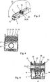
Anhand der
Die
Umgekehrt kann es natürlich auch vorgesehen sein, dass die Gleitschiene
In
Das andere Ende des Hebels
Bezogen auf den ziehenden Antrieb einer Tür ergibt sich ein Übersetzungsverhältnis gemäß
In nachteiliger Weise zeigt die
Hier setzt die Erfindung ein, die neuartige Drehmomentverhältnisse erzeugt, wie es später anhand der
Zunächst wird jedoch auf
Die
Die
Die
Wichtig hierbei ist, dass eine einzige Drehmomentkurve
Hieraus ergibt sich, dass ein und die gleiche Drehmomentkurve sowohl für den ziehenden als auch für den drückenden Betrieb verwendet wird und lediglich die Startpunkte
Dies macht die Herstellung der beiden Kurvenscheiben
Aus dem Vergleich der
Die
Die Kurvenscheibe
Die Endposition der Ablaufkurve
Die dargestellten Kurven nach den
Unter Einwirkung des Motors
Grundsätzlich öffnet der Motor
Die ideale Kurve nach
BezugszeichenlisteLIST OF REFERENCE NUMBERS
- 11
- Trägerblechsupport plate
- 22
- Federblockspring block
- 33
- KurvenscheibenmodulCAM module
- 44
- Steuerungsmodulcontrol module
- 55
- Motorengine
- 66
- Encoderencoder
- 77
- Motorwellemotor shaft
- 88th
- KugelgewindespindelBall screw
- 99
- Lagercamp
- 1010
- Spindelmutterspindle nut
- 1111
- Zahnstangerack
- 1212
- Verzahnunggearing
- 1313
- Stößeltappet
- 1414
- Absolutweggeberabsolute position
- 1515
- ZahnstangenführungRack guide
- 1616
- Anschlaghaltersupport holder
- 1717
- Anschlagattack
- 1818
- Gewindethread
- 1919
- Abtriebswelleoutput shaft
- 2020
- Kurvenscheibecam
- 2121
- Lagerungstorage
- 2222
- Verzahnunggearing
- 2323
- Rollerole
- 2424
- Rollenachseroller axis
- 2525
- DruckstückPressure piece
- 2626
- Stiftpen
- 2727
- Ansatzapproach
- 2828
- Druckfedercompression spring
- 2929
- Anschlagkantestop edge
- 3030
- Federtellerspring plate
- 3131
- Spannschraube a, bClamping screw a, b
- 3232
- Bolzenbolt
- 3333
- Schlitzslot
- 3434
- Gleitschieneslide
- 3535
- Hebellever
- 3636
- Aufnahmebuchsereceiving socket
- 3737
- Hebellever
- 3838
- Hebellever
- 3939
- Drehlagerpivot bearing
- 4040
- Lagerbockbearing block
- 4141
- 4242
- 4343
- Position (Startposition Gleitgestänge)Position (starting position sliding linkage)
- 4444
- Position (Startposition Normalgestänge)Position (start position normal linkage)
- 4545
- Pfeilrichtungarrow
- 4646
- Positionposition
- 4747
- Ablaufkurveflow curve
- 4848
- Pfeilrichtungarrow
- 4949
- 5050
- Pfeilrichtung (Öffnung)Arrow direction (opening)
- 5151
- Wandbefestigungwall mounting
- 5252
- Pfeilrichtungarrow
- 5353
- Drehmomentkurvetorque curve
Claims (12)
Priority Applications (4)
| Application Number | Priority Date | Filing Date | Title |
|---|---|---|---|
| DE102006002751A DE102006002751B4 (en) | 2006-01-20 | 2006-01-20 | Swing door operator with cam |
| SE0700075A SE530067C2 (en) | 2006-01-20 | 2007-01-15 | Drive device with camshaft for rotatable door wings |
| CH00049/07A CH701926B1 (en) | 2006-01-20 | 2007-01-15 | Swing Door Operator with cam. |
| IT000065A ITMI20070065A1 (en) | 2006-01-20 | 2007-01-18 | DRIVE FOR HINGED DOOR WITH DISC CAM |
Applications Claiming Priority (1)
| Application Number | Priority Date | Filing Date | Title |
|---|---|---|---|
| DE102006002751A DE102006002751B4 (en) | 2006-01-20 | 2006-01-20 | Swing door operator with cam |
Publications (2)
| Publication Number | Publication Date |
|---|---|
| DE102006002751A1 DE102006002751A1 (en) | 2007-09-20 |
| DE102006002751B4 true DE102006002751B4 (en) | 2012-11-22 |
Family
ID=38374660
Family Applications (1)
| Application Number | Title | Priority Date | Filing Date |
|---|---|---|---|
| DE102006002751A Expired - Fee Related DE102006002751B4 (en) | 2006-01-20 | 2006-01-20 | Swing door operator with cam |
Country Status (4)
| Country | Link |
|---|---|
| CH (1) | CH701926B1 (en) |
| DE (1) | DE102006002751B4 (en) |
| IT (1) | ITMI20070065A1 (en) |
| SE (1) | SE530067C2 (en) |
Cited By (1)
| Publication number | Priority date | Publication date | Assignee | Title |
|---|---|---|---|---|
| CN109415921A (en) * | 2016-06-27 | 2019-03-01 | D & D集团有限公司 | Articulation Mechanisms and Articulation Components |
Families Citing this family (3)
| Publication number | Priority date | Publication date | Assignee | Title |
|---|---|---|---|---|
| DE102012104450B4 (en) * | 2012-05-23 | 2015-12-31 | Gu Automatic Gmbh | Drive for a door leaf or a window sash |
| EP2921626B2 (en) * | 2014-03-19 | 2024-02-21 | Gretsch-Unitas GmbH Baubeschläge | Door closer |
| DE102015213711B4 (en) * | 2015-07-21 | 2025-11-27 | Geze Gmbh | Electromechanical drive and corresponding fire door |
Citations (2)
| Publication number | Priority date | Publication date | Assignee | Title |
|---|---|---|---|---|
| EP1505239A1 (en) * | 2003-08-06 | 2005-02-09 | agtatec ag | Drive for a wing, in particular rotary drive for a door, a window or the like |
| EP1505242A1 (en) * | 2003-08-06 | 2005-02-09 | agtatec ag | Drive for a wing, in particular rotary drive for a door, a window or the like |
-
2006
- 2006-01-20 DE DE102006002751A patent/DE102006002751B4/en not_active Expired - Fee Related
-
2007
- 2007-01-15 CH CH00049/07A patent/CH701926B1/en unknown
- 2007-01-15 SE SE0700075A patent/SE530067C2/en unknown
- 2007-01-18 IT IT000065A patent/ITMI20070065A1/en unknown
Patent Citations (2)
| Publication number | Priority date | Publication date | Assignee | Title |
|---|---|---|---|---|
| EP1505239A1 (en) * | 2003-08-06 | 2005-02-09 | agtatec ag | Drive for a wing, in particular rotary drive for a door, a window or the like |
| EP1505242A1 (en) * | 2003-08-06 | 2005-02-09 | agtatec ag | Drive for a wing, in particular rotary drive for a door, a window or the like |
Cited By (2)
| Publication number | Priority date | Publication date | Assignee | Title |
|---|---|---|---|---|
| CN109415921A (en) * | 2016-06-27 | 2019-03-01 | D & D集团有限公司 | Articulation Mechanisms and Articulation Components |
| CN109415921B (en) * | 2016-06-27 | 2021-04-13 | D & D集团有限公司 | Articulation Mechanisms and Articulation Components |
Also Published As
| Publication number | Publication date |
|---|---|
| CH701926B1 (en) | 2011-04-15 |
| DE102006002751A1 (en) | 2007-09-20 |
| ITMI20070065A1 (en) | 2007-07-21 |
| SE530067C2 (en) | 2008-02-26 |
Similar Documents
| Publication | Publication Date | Title |
|---|---|---|
| EP2211004B1 (en) | Locking device | |
| DE4201069C2 (en) | Gear for a door lock, in particular a smoke protection door lock | |
| EP1298274A1 (en) | Doorwing drive system with spring closing means | |
| EP4232674B1 (en) | Door drive for vehicle sliding door system | |
| EP3325751A1 (en) | Drive for a rotatable wing | |
| EP3656960B1 (en) | Vehicle hatch kinematics | |
| DE102014207217B3 (en) | Swing door drive | |
| CH701926B1 (en) | Swing Door Operator with cam. | |
| EP2348177B1 (en) | Locking unit of an espagnolette fitting | |
| EP3420167A1 (en) | Actuating arm drive | |
| EP2169156A1 (en) | Mortise lock without deadbolt | |
| EP3348773B1 (en) | Device for opening, closing and locking lamellae of a lamella construction | |
| EP2248958B1 (en) | Sliding sunroof | |
| DE102008003557B4 (en) | Height-adjustable door hinge with driving gears | |
| DE102013212650B3 (en) | Device for controlling the closing sequence of a two-leaf revolving door system | |
| DE102013212651B3 (en) | Device for controlling the closing sequence of a two-leaf revolving door system | |
| EP1707726B1 (en) | Device for opening and closing a window or door slidably arranged on a frame | |
| EP3523160A1 (en) | Gearing arrangement for a spindle drive, spindle drive, and vehicle seat | |
| DE102011018739A1 (en) | Swing door actuator receptacle set | |
| DE202015003728U1 (en) | Swing door with torsion bar | |
| DE10211736B4 (en) | Electric drive for shutters or the like | |
| DE102024107399B3 (en) | Drive for a door or window with improved efficiency | |
| DE102023208573B3 (en) | Automatic drive for a revolving door and revolving door | |
| DE102023208570B3 (en) | Automatic drive for a revolving door and revolving door | |
| DE202012011180U1 (en) | Door closers |
Legal Events
| Date | Code | Title | Description |
|---|---|---|---|
| OM8 | Search report available as to paragraph 43 lit. 1 sentence 1 patent law | ||
| OP8 | Request for examination as to paragraph 44 patent law | ||
| R018 | Grant decision by examination section/examining division | ||
| R026 | Opposition filed against patent |
Effective date: 20130221 |
|
| R079 | Amendment of ipc main class |
Free format text: PREVIOUS MAIN CLASS: E05F0015120000 Ipc: E05F0015611000 |
|
| R079 | Amendment of ipc main class |
Free format text: PREVIOUS MAIN CLASS: E05F0015120000 Ipc: E05F0015611000 Effective date: 20141208 |
|
| R031 | Decision of examining division/federal patent court maintaining patent unamended now final | ||
| R081 | Change of applicant/patentee |
Owner name: LANDERT GROUP AG, CH Free format text: FORMER OWNER: LANDERT-MOTOREN AG, BUELACH, CH Owner name: LANDERT MOTOREN AG, CH Free format text: FORMER OWNER: LANDERT-MOTOREN AG, BUELACH, CH |
|
| R082 | Change of representative |
Representative=s name: RIEBLING, PETER, DIPL.-ING. DR.-ING., DE |
|
| R081 | Change of applicant/patentee |
Owner name: LANDERT GROUP AG, CH Free format text: FORMER OWNER: LANDERT MOTOREN AG, BUELACH, CH |
|
| R082 | Change of representative |
Representative=s name: RIEBLING, PETER, DIPL.-ING. DR.-ING., DE |
|
| R119 | Application deemed withdrawn, or ip right lapsed, due to non-payment of renewal fee |