DE102005063159B4 - Method for controlling matrix displays - Google Patents
Method for controlling matrix displays Download PDFInfo
- Publication number
- DE102005063159B4 DE102005063159B4 DE102005063159A DE102005063159A DE102005063159B4 DE 102005063159 B4 DE102005063159 B4 DE 102005063159B4 DE 102005063159 A DE102005063159 A DE 102005063159A DE 102005063159 A DE102005063159 A DE 102005063159A DE 102005063159 B4 DE102005063159 B4 DE 102005063159B4
- Authority
- DE
- Germany
- Prior art keywords
- matrix
- line
- brightness
- matrices
- addressing
- Prior art date
- Legal status (The legal status is an assumption and is not a legal conclusion. Google has not performed a legal analysis and makes no representation as to the accuracy of the status listed.)
- Expired - Fee Related
Links
Classifications
-
- G—PHYSICS
- G09—EDUCATION; CRYPTOGRAPHY; DISPLAY; ADVERTISING; SEALS
- G09G—ARRANGEMENTS OR CIRCUITS FOR CONTROL OF INDICATING DEVICES USING STATIC MEANS TO PRESENT VARIABLE INFORMATION
- G09G3/00—Control arrangements or circuits, of interest only in connection with visual indicators other than cathode-ray tubes
- G09G3/20—Control arrangements or circuits, of interest only in connection with visual indicators other than cathode-ray tubes for presentation of an assembly of a number of characters, e.g. a page, by composing the assembly by combination of individual elements arranged in a matrix no fixed position being assigned to or needed to be assigned to the individual characters or partial characters
- G09G3/22—Control arrangements or circuits, of interest only in connection with visual indicators other than cathode-ray tubes for presentation of an assembly of a number of characters, e.g. a page, by composing the assembly by combination of individual elements arranged in a matrix no fixed position being assigned to or needed to be assigned to the individual characters or partial characters using controlled light sources
- G09G3/30—Control arrangements or circuits, of interest only in connection with visual indicators other than cathode-ray tubes for presentation of an assembly of a number of characters, e.g. a page, by composing the assembly by combination of individual elements arranged in a matrix no fixed position being assigned to or needed to be assigned to the individual characters or partial characters using controlled light sources using electroluminescent panels
- G09G3/32—Control arrangements or circuits, of interest only in connection with visual indicators other than cathode-ray tubes for presentation of an assembly of a number of characters, e.g. a page, by composing the assembly by combination of individual elements arranged in a matrix no fixed position being assigned to or needed to be assigned to the individual characters or partial characters using controlled light sources using electroluminescent panels semiconductive, e.g. using light-emitting diodes [LED]
- G09G3/3208—Control arrangements or circuits, of interest only in connection with visual indicators other than cathode-ray tubes for presentation of an assembly of a number of characters, e.g. a page, by composing the assembly by combination of individual elements arranged in a matrix no fixed position being assigned to or needed to be assigned to the individual characters or partial characters using controlled light sources using electroluminescent panels semiconductive, e.g. using light-emitting diodes [LED] organic, e.g. using organic light-emitting diodes [OLED]
- G09G3/3216—Control arrangements or circuits, of interest only in connection with visual indicators other than cathode-ray tubes for presentation of an assembly of a number of characters, e.g. a page, by composing the assembly by combination of individual elements arranged in a matrix no fixed position being assigned to or needed to be assigned to the individual characters or partial characters using controlled light sources using electroluminescent panels semiconductive, e.g. using light-emitting diodes [LED] organic, e.g. using organic light-emitting diodes [OLED] using a passive matrix
-
- G—PHYSICS
- G09—EDUCATION; CRYPTOGRAPHY; DISPLAY; ADVERTISING; SEALS
- G09G—ARRANGEMENTS OR CIRCUITS FOR CONTROL OF INDICATING DEVICES USING STATIC MEANS TO PRESENT VARIABLE INFORMATION
- G09G3/00—Control arrangements or circuits, of interest only in connection with visual indicators other than cathode-ray tubes
- G09G3/20—Control arrangements or circuits, of interest only in connection with visual indicators other than cathode-ray tubes for presentation of an assembly of a number of characters, e.g. a page, by composing the assembly by combination of individual elements arranged in a matrix no fixed position being assigned to or needed to be assigned to the individual characters or partial characters
- G09G3/2007—Display of intermediate tones
- G09G3/2077—Display of intermediate tones by a combination of two or more gradation control methods
- G09G3/2081—Display of intermediate tones by a combination of two or more gradation control methods with combination of amplitude modulation and time modulation
-
- G—PHYSICS
- G09—EDUCATION; CRYPTOGRAPHY; DISPLAY; ADVERTISING; SEALS
- G09G—ARRANGEMENTS OR CIRCUITS FOR CONTROL OF INDICATING DEVICES USING STATIC MEANS TO PRESENT VARIABLE INFORMATION
- G09G5/00—Control arrangements or circuits for visual indicators common to cathode-ray tube indicators and other visual indicators
- G09G5/18—Timing circuits for raster scan displays
-
- G—PHYSICS
- G09—EDUCATION; CRYPTOGRAPHY; DISPLAY; ADVERTISING; SEALS
- G09G—ARRANGEMENTS OR CIRCUITS FOR CONTROL OF INDICATING DEVICES USING STATIC MEANS TO PRESENT VARIABLE INFORMATION
- G09G2310/00—Command of the display device
- G09G2310/02—Addressing, scanning or driving the display screen or processing steps related thereto
- G09G2310/0202—Addressing of scan or signal lines
- G09G2310/0205—Simultaneous scanning of several lines in flat panels
-
- G—PHYSICS
- G09—EDUCATION; CRYPTOGRAPHY; DISPLAY; ADVERTISING; SEALS
- G09G—ARRANGEMENTS OR CIRCUITS FOR CONTROL OF INDICATING DEVICES USING STATIC MEANS TO PRESENT VARIABLE INFORMATION
- G09G2360/00—Aspects of the architecture of display systems
- G09G2360/16—Calculation or use of calculated indices related to luminance levels in display data
-
- G—PHYSICS
- G09—EDUCATION; CRYPTOGRAPHY; DISPLAY; ADVERTISING; SEALS
- G09G—ARRANGEMENTS OR CIRCUITS FOR CONTROL OF INDICATING DEVICES USING STATIC MEANS TO PRESENT VARIABLE INFORMATION
- G09G3/00—Control arrangements or circuits, of interest only in connection with visual indicators other than cathode-ray tubes
- G09G3/20—Control arrangements or circuits, of interest only in connection with visual indicators other than cathode-ray tubes for presentation of an assembly of a number of characters, e.g. a page, by composing the assembly by combination of individual elements arranged in a matrix no fixed position being assigned to or needed to be assigned to the individual characters or partial characters
- G09G3/2007—Display of intermediate tones
- G09G3/2014—Display of intermediate tones by modulation of the duration of a single pulse during which the logic level remains constant
-
- G—PHYSICS
- G09—EDUCATION; CRYPTOGRAPHY; DISPLAY; ADVERTISING; SEALS
- G09G—ARRANGEMENTS OR CIRCUITS FOR CONTROL OF INDICATING DEVICES USING STATIC MEANS TO PRESENT VARIABLE INFORMATION
- G09G3/00—Control arrangements or circuits, of interest only in connection with visual indicators other than cathode-ray tubes
- G09G3/20—Control arrangements or circuits, of interest only in connection with visual indicators other than cathode-ray tubes for presentation of an assembly of a number of characters, e.g. a page, by composing the assembly by combination of individual elements arranged in a matrix no fixed position being assigned to or needed to be assigned to the individual characters or partial characters
- G09G3/22—Control arrangements or circuits, of interest only in connection with visual indicators other than cathode-ray tubes for presentation of an assembly of a number of characters, e.g. a page, by composing the assembly by combination of individual elements arranged in a matrix no fixed position being assigned to or needed to be assigned to the individual characters or partial characters using controlled light sources
- G09G3/30—Control arrangements or circuits, of interest only in connection with visual indicators other than cathode-ray tubes for presentation of an assembly of a number of characters, e.g. a page, by composing the assembly by combination of individual elements arranged in a matrix no fixed position being assigned to or needed to be assigned to the individual characters or partial characters using controlled light sources using electroluminescent panels
- G09G3/32—Control arrangements or circuits, of interest only in connection with visual indicators other than cathode-ray tubes for presentation of an assembly of a number of characters, e.g. a page, by composing the assembly by combination of individual elements arranged in a matrix no fixed position being assigned to or needed to be assigned to the individual characters or partial characters using controlled light sources using electroluminescent panels semiconductive, e.g. using light-emitting diodes [LED]
- G09G3/3208—Control arrangements or circuits, of interest only in connection with visual indicators other than cathode-ray tubes for presentation of an assembly of a number of characters, e.g. a page, by composing the assembly by combination of individual elements arranged in a matrix no fixed position being assigned to or needed to be assigned to the individual characters or partial characters using controlled light sources using electroluminescent panels semiconductive, e.g. using light-emitting diodes [LED] organic, e.g. using organic light-emitting diodes [OLED]
- G09G3/3266—Details of drivers for scan electrodes
Landscapes
- Engineering & Computer Science (AREA)
- Physics & Mathematics (AREA)
- Computer Hardware Design (AREA)
- General Physics & Mathematics (AREA)
- Theoretical Computer Science (AREA)
- Multimedia (AREA)
- Control Of Indicators Other Than Cathode Ray Tubes (AREA)
- Liquid Crystal (AREA)
- Electroluminescent Light Sources (AREA)
- Liquid Crystal Display Device Control (AREA)
Abstract
Verfahren zur Ansteuerung von Matrixanzeigen (D), welche aus mehreren als Zeilen (i) und Spalten (j) ausgebildeten Reihen mit einzelnen Pixeln (ij) aufgebaut sind, wobei einzelne Reihen selektiv angesteuert werden, indem Zeilen (i) für eine bestimmte Zeilenadressierzeit (ti) aktiviert und die Spalten (j) korreliert zu der aktivierten Zeile (i) entsprechend der gewünschten Helligkeit (Dij) in den Pixeln (ij) mit einem Betriebsstrom (I) oder einer entsprechenden Spannung beaufschlagt werden, dadurch gekennzeichnet, dass die Zeilenadressierzeit (ti) für jede Zeile (i) in Abhängigkeit von der maximalen Helligkeit aller Spalten (Di max) der Zeile (i) festgelegt wird.Method for driving matrix displays (D), which are constructed from a plurality of rows (ij) formed as rows (i) and columns (j), wherein individual rows are selectively driven by dividing rows (i) for a specific row addressing time ( t i ) is activated and the columns (j) correlated to the activated line (i) are subjected to an operating current (I) or a corresponding voltage in accordance with the desired brightness (D ij ) in the pixels (ij), characterized in that the Line address time (t i ) for each line (i) is determined in dependence on the maximum brightness of all columns (D i max ) of the line (i).

Description
Die Erfindung betrifft ein Verfahren zur Ansteuerung von Matrixanzeigen, welche aus mehreren als Zeilen und Spalten ausgebildeten Reihen mit einzelnen Pixeln aufgebaut sind, wobei einzelne Reihen selektiv angesteuert werden, indem Zeilen für eine bestimmte Zeilenadressierzeit aktiviert und die Spalten korreliert zu der aktivierten Zeile entsprechend der gewünschten Helligkeit in den Pixeln mit einem Betriebsstrom oder einer entsprechenden Spannung, d. h. einen elektrischen Signal zur Ansteuerung, beaufschlagt werden.The The invention relates to a method for controlling matrix displays, which consists of several rows and columns formed rows are constructed with individual pixels, with individual rows selectively driven be by adding lines for activates a particular row addressing time and correlates the columns to the activated line according to the desired brightness in the pixels with an operating current or voltage, d. H. an electrical signal for driving, be acted upon.
Im Folgenden werden die horizontalen Reihen als Zeilen und die orthogonal dazu verlaufenden, vertikalen Reihen als Spalten bezeichnet. Dies dient dem einfacheren Verständnis. Die Erfindung ist jedoch nicht auf genau diese Anordnung beschränkt. Insbesondere ist es möglich, die Zeilen und Spalten in ihrer Funktion zu vertauschen oder eine nicht orthogonale Beziehung zwischen den Zeilen und Spalten zu wählen.in the Following are the horizontal rows as rows and the orthogonal ones extending to vertical rows called columns. This serves the easier understanding. However, the invention is not limited to this exact arrangement. Especially Is it possible, to swap the rows and columns in their function or one to choose non-orthogonal relationship between the rows and columns.
Die Bilddaten bzw. die gewünschte Helligkeit einzelner Pixel ij werden mit der nachfolgend dargestellten Matrix D beschrieben.The Image data or the desired Brightness of individual pixels ij are shown below Matrix D described.

Die Indizes entsprechen den Positionen der Pixel auf dem Display, welches durch die Matrix bzw. Matrixanzeige D gegeben ist. Jede Zeile i der Matrix D und jede Spalte j auf der Matrix D entsprechen jeweils der geometrischen Zeile und Spalte auf dem Display. Jedem ansteuerbaren Pixel ij der Matrixanzeige D ist eine Pixel-Diode oder dgl. Element zur Erzeugung eines Pixels einer Anzeige zugeordnet. Die zeitlich gemittelte Leuchtintensität (entsprechend der Helligkeit Du) in jedem Pixel korrespondiert mit dem entsprechenden Element in der Matrix D. Alle Einträge der Matrix D ergeben zusammen das darzustellende Bild.The Indices correspond to the positions of the pixels on the display, which given by the matrix or matrix display D. Every line i the matrix D and each column j on the matrix D correspond respectively the geometric line and column on the display. Each controllable Pixel ij of the matrix display D is a pixel diode or the like element associated with a display for generating a pixel. The time average luminous intensity (corresponding to the brightness you) in each pixel corresponds with the corresponding element in the matrix D. All entries of the matrix D together form the image to be displayed.
Die
Pixel ij auf der Matrixanzeige D, von denen jedes insbesondere als
OLED (Organic Light Emitting Diode) ausgebildet sein kann, werden
bisher zeilenweise aktiviert. Dazu werden die OLEDs auf einer selektierten
Zeile i durch einen Schalter aktiviert, indem sie z. B. mit Masse
verbunden werden. In den Spalten j wird jeweils ein Betriebsstrom
I eingeprägt,
der die Pixel ij im Schnittpunkt dieser Zeile i und den Spalten
j zum Leuchten bringt. Die Leuchtintensität L ist in erster Nahrung proportional
zu Ladung, die während
der aktiven Phase (Zeilenadressierzeit) eingeprägt und in dem OLED-Pixel strahlend
rekombiniert wird. Bei höherer
Wiederholungsfrequenz der Adressierung der Display-Matrix bzw. Matrixanzeige
D nimmt das menschliche Auge folgenden Mittelwert der Intensität L des
Lichts wahr: 
TFrame ist die Gesamtzeit, die für den Aufbau
eines kompletten Bildes benötigt
wird, wenn alle n Zeilen der Matrixanzeige D einmal aktiviert werden.
Der Betriebsstrom IOLED bzw. I oder I0 wird in jedem Pixel eingeprägt. Bei
einer Amplitudenmodulation zur Helligkeitssteuerung ist der Betriebsstrom über den
Zeitraum TFrame/n aktiv, welcher der Zeilenadressierzeit
entspricht. Bei einer Pulsweitenmodulation ist die Dauer des Betriebsstroms
kleiner, nämlich
d·TFrame/n. Dabei ist d das Pulsweitenmodulations-Tastverhältnis und
liegt zwischen Null und Eins: 
Der Strom I0 ist nun unabhängig von der Leuchtintensität des Pixels konstant. Die Intensität L wird mittels des Tastverhältnisses d eingestellt. Eine derartige Helligkeitssteuerung ist im Vergleich zu einer Amplitudenmodulation einfacher und genauer, da die Zeiteinheiten in der Elektronik sehr genau eingestellt werden können und folglich auch d. Nur ein Referenzstrom I0 reicht zur Ansteuerung aller Pixel ij aus. Bei der Amplitudenmodulation muss dagegen jeweils die Amplitude entsprechend der gewünschten Helligkeit Dij angepasst werden.The current I 0 is now constant regardless of the luminous intensity of the pixel. The intensity L is set by means of the duty cycle d. Such brightness control is simpler and more accurate compared to amplitude modulation because the units of time in the electronics can be set very accurately, and consequently d. Only one reference current I 0 is sufficient to drive all pixels ij. For amplitude modulation, on the other hand, the amplitude must be adjusted according to the desired brightness D ij .
Durch die Ansteuerung aller Spalten j jeweils nur einer Zeile i kann jede Diode bzw. jedes Pixel ij maximal nur zu einem n-tel der Gesamtzeit TFrame aktiv sein. Um auf eine bestimmte Durchschnittshelligkeit Dij zu kommen, muss der entsprechende Betriebsstrom also im Vergleich zu dem Fall, in dem ein Pixel über die Gesamtzeit TFrame mit Betriebstrom versorgt würde, mit der Anzahl n der Zeilen multipliziert werden. Das heißt, je höher die Zeilenanzahl ist, umso höher muss der gepulste Betriebsstrom I bzw. I0 sein. Außerdem ist der Betriebsstrom bei einer Pulsweitenmodulation zur Helligkeitseinstellung immer hoch, auch wenn das anzusteuernde Pixels ij sehr dunkel ist. In diesem Fall ist lediglich die Aufschaltzeit des Betriebsstroms sehr kurz.By controlling all columns j of only one row i each diode or each pixel ij can be active only a maximum of one nth of the total time T frame . In order to arrive at a certain average brightness D ij , the corresponding operating current thus has to be multiplied by the number n of lines in comparison with the case in which a pixel is supplied with operating current over the total time T frame . That is, the higher the number of lines, the higher must be the pulsed operating current I or I 0 . In addition, the operating current in a pulse width modulation for brightness adjustment is always high, even if the pixel to be controlled ij is very dark. In this case, only the turn-on time of the operating current is very short.
Der hohe Betriebsstrom kann jedoch zu einer signifikanten Reduzierung der OLED-Lebensdauer führen. Um den hohen benötigten Betriebsstrom zu erreichen, muss auch die Spannung an den OLEDs erhöht werden, wodurch der Leistungsverbrauch ansteigt und der Wirkungsgrad sinkt. Diese erhöhte Verlustleistung entlädt nicht nur den Akku bzw. die Batterie schneller, sondern macht das Display auch wärmer, wodurch die Lebensdauer ebenfalls reduziert wird.Of the However, high operating current can lead to a significant reduction lead the OLED life. To the high needed Operating current must also be the voltage at the OLEDs increase, whereby the power consumption increases and the efficiency decreases. This increased Power loss discharges not only the battery or the battery faster, but does that Display also warmer, whereby the life is also reduced.
Um dennoch ein großes, hoch auflösendes Display zu realisieren, könnte wie bei LCDs (Liquid Crystal Display, Flüssigkristallanzeige) eine sog. "aktive Matrix" eingesetzt werden, wodurch der Betriebsstrom nicht mehr gepulst geliefert wird sondern als Konstantstrom vorliegt. Allerdings erfordert eine Aktive-Matrix-Ansteuerung (TFT-Backplane) für ein OLED-Display signifikante Zusatzkosten.Around nevertheless a big, high resolution Could realize a display as with LCDs (liquid crystal display, liquid crystal display) a so-called "active matrix" are used, whereby the operating current is no longer supplied pulsed but is present as a constant current. However, an active matrix control (TFT backplane) requires for a OLED display significant additional costs.
Aus
der den nächstkommenden
Stand der Technik bildenden
Die
Aufgabe der Erfindung ist es, ein Verfahren zur Ansteuerung von Matrixanzeigen entsprechend der eingangs genannten Art vorzuschlagen, mit dem die Lebensdauer von OLED-Display erhöht oder die Performance einer beliebigen Matrixanzeige verbessert werden kann.task The invention is a method for driving matrix displays to propose according to the type mentioned, with the Lifespan of OLED display increased or improve the performance of any matrix display can.
Diese Aufgabe wird erfindungsgemäß dadurch gelöst, dass die Zeilenadressierzeit ti für jede Zeile i in Abhängigkeit von der maximalen Helligkeit D'max aller Spalten j der Zeile i festgelegt wird. Dadurch kann die Zeilenadressierzeit ti kleiner oder gleich einer konstanten Zeilenadressierzeit tL gewählt werden, die sich ergibt, wenn jede Zeile der Matrixanzeige solange adressiert wird, dass mit dem aufgeprägten Betriebsstrom eine maximale Pixelhelligkeit Dmax erreicht werden könnte. Die erfindungsgemäße Zeilenadressierzeit ti entspricht also der konstanten Zeilenadressierzeit tL multipliziert mit dem Verhältnis der maximalen Helligkeit Di max der Pixel in allen Spalten j der Zeile i zu der maximal möglichen Pixelhelligkeit Dmax in der gesamten Matrixanzeige.This object is achieved according to the invention in that the row addressing time t i for each row i is determined as a function of the maximum brightness D ' max of all columns j of the row i. As a result, the row addressing time t i can be chosen to be less than or equal to a constant row addressing time t L , which results if each row of the matrix display is addressed so long that a maximum pixel brightness D max could be achieved with the impressed operating current. The inventive row addressing time t i thus corresponds to the constant row addressing time t L multiplied by the ratio of the maximum brightness D i max of the pixels in all columns j of the row i to the maximum possible pixel brightness D max in the entire matrix display.
Die maximale Pixelhelligkeit Dmax ist definiert als die Leuchtintensität (Helligkeit) in einem Pixel ij, die erreicht wird, wenn das Pixel während der konstanten Zeilenadressierzeit tL mit dem Betriebsstrom I0 beaufschlagt wird. Daraus ergibt sich, dass die Zeitsumme TSum der Zeilenadressierzeiten ti über die Anzahl n aller Zeilen kleiner oder gleich der Gesamtzeit TFrame zur Aktivierung aller n Zeilen ist, welche durch das n-fache der konstanten Zeilenadressierzeit tL gegeben ist. Bei konstantem Betriebsstrom I0 kann daher die Gesamtzeit zur Ansteuerung der Matrixanzeige erfindungsgemäß auf die Zeitsumme TSum < TFrame der Zeilenadressierzeiten reduziert werden. Dies ermöglicht bspw. eine höhere Bildwiederholfrequenz und steigert damit die erreichbare Performance einer Matrixanzeige.The maximum pixel brightness D max is defined as the luminous intensity (brightness) in a pixel ij which is reached when the operating current I 0 is applied to the pixel during the constant row addressing time t L. It follows that the time sum T Sum of the row addressing times t i over the number n of all rows is less than or equal to the total time T frame for activating all n rows, which is given by n times the constant row addressing time t L. At constant operating current I 0 , the total time for driving the matrix display can therefore be reduced according to the invention to the time sum T Sum <T Frame of the row addressing times. This allows, for example, a higher refresh rate and thus increases the achievable performance of a matrix display.
Da die Leuchtintensität eines Pixels ij in erster Näherung proportional zu der Ladung ist, die in ein Pixel ij eingeprägt wird, d. h. proportional zu dem Produkt aus Zeilenadressierzeit ti und Betriebsstrom ist, kann die Abhängigkeit der Zeilenadressierzeit ti von der maximalen Helligkeit über die Spalten einer Zeile auch verwendet werden, um den Betriebsstrom zu reduzieren. Dazu kann die Gesamtzeit TFrame zur Aktivierung aller Zeilen i konstant gehalten werden, so dass die Summe der Zeilenadressierzeiten t'i über alle Zeilen n der Gesamtzeit TFrame entspricht. Die Zeilenadressierzeiten t'i werden gemäß dieser erfindungsgemäßen Verfahrensvariante also entsprechend verlängert, so dass ihre Summe gleich der Gesamtzeit TFrame ist. Gleichzeitig kann erfindungsgemäß der Betriebstrom I0 um das Verhältnis der Zeitsumme TSum der (unbedingt benötigten) Zeilenadressierzeiten ti aller Zeilen n zu der Gesamtzeit (TFrame) zur Aktivierung aller Zeilen mit konstanter Zeilenadressierzeit tL auf den Betriebstrom I gesenkt werden. Die Leuchtintensität der einzelnen Pixel verändert sich dabei nicht, weil das Produkt aus der Zeilenadressierzeit und dem Betriebsstrom ti·I0 = t'i·I1 konstant bleibt. Bei OLEDs ist die Quanteneffizienz η im Bereich eines geringeren Betriebsstroms in der Regel größer als bei höherem Betriebsstrom. Daher kann der Betriebstrom I1 zusätzlich um das Verhältnis der Quanteneffizienzen η(I1)/η(I0) reduziert werden. Nachfolgend wird auch die (verlängerte bzw. auf TFrame normierte) Zeilenadressierzeit t'i der Einfachheit halber als ti bezeichnet.Since the luminous intensity of a pixel ij is, to a first approximation, proportional to the charge impressed into a pixel ij, ie, proportional to the product of row addressing time t i and operating current, the dependence of the row addressing time t i on the maximum brightness across the columns a line can also be used to reduce the operating current. For this purpose, the total time T frame for activating all lines i can be kept constant, so that the sum of the line addressing times t ' i over all lines n corresponds to the total time T frame . The Zeilenadressierzeiten t ' i are thus extended accordingly according to this variant of the method according to the invention, so that their sum is equal to the total time T frame . At the same time according to the invention, the operating current I 0 to the ratio of the time sum T sum of (absolutely required) Zeilenadressierzeiten t i all rows n to the total time (T frame ) to activate all lines with constant Zeilenadres s t L be lowered to the operating current I. The luminous intensity of the individual pixels does not change because the product of the row addressing time and the operating current t i * I 0 = t ' i * I 1 remains constant. In the case of OLEDs, the quantum efficiency η in the region of a lower operating current is generally greater than at a higher operating current. Therefore, the operating current I 1 can be additionally reduced by the ratio of the quantum efficiencies η (I 1 ) / η (I 0 ). Hereinbelow, the line addressing time t ' i (normalized to T frame ) is also referred to as t i for the sake of simplicity.
Durch die erfindungsgemäße Anpassung der Zeilenadressierzeiten ti zur Adressierung der Diodenpixel kann also die selektive Phase (Zeilenadressierzeit) der einzelnen Diodenpixel ij des Displays D, d. h. die Zeit, während der das Diodenpixel ij mit dem Betriebsstrom I beaufschlagt wird, deutlich verlängert werden. Der aktive Betriebsstrom I1 kann dabei umgekehrt proportional zur Dauer des selektierten Phase reduziert werden. Damit kann der Wirkungsgrad der Matrixanzeige D insgesamt erhöht und insbesondere bei OLED-Displays die Lebensdauer verlängert werden. Eine grundlegende Idee dieser Erfindung liegt also darin, die Dauer des Betriebsstroms durch eine zeilenabhängige Verkürzung bzw. Anpassung der Zeilenadressierzeiten zu verlängern. Da für eine bestimmte Leuchtintensität primär die Ladung entscheidend ist, bedeutet mehr Zeit zur Einprägung des Betriebsstroms somit einen in der Amplitude niedrigeren Strom.By the inventive adaptation of the row i t for addressing the diode pixels so can the selective phase (row addressing) of the individual diode pixels ij of the display D, that is the time during which the diode pixels ij is supplied with the operating current I, to be extended significantly. The active operating current I 1 can be reduced inversely proportional to the duration of the selected phase. Thus, the efficiency of the matrix display D can be increased overall and in particular in OLED displays, the lifetime can be extended. A basic idea of this invention is therefore to extend the duration of the operating current by a line-dependent shortening or adaptation of the Zeilenadressierzeiten. Since the charge is primarily decisive for a specific luminous intensity, more time for imprinting the operating current thus means a lower current in the amplitude.
Eine verbesserte Handhabung und eine weitere Reduzierung des Betriebsstroms kann erreicht werden, wenn die Matrixanzeige D in mehrere Matrizen S, M zerlegt wird, die separat angesteuert werden. Die Überlagerung aller Matrizen erzeugt dann das Bild der Matrixanzeige D in der gewünschten Helligkeit Dij der jeweiligen Pixel ij. Dabei sollte die aus der Summe der Einzelhelligkeiten der mehreren Matrizen gebildete Gesamthelligkeit Dij der insgesamt gewünschten Helligkeit Dij der Matrixanzeige D in dem Pixel ij entsprechen. Die Matrizen können erfindungsgemäß nacheinander oder ineinander verschachtelt, vorzugsweise jeweils unter Anwendung des vorbeschriebenen Verfahrens, zeilen- und spaltenweise abgearbeitet werden. Im Falle einer Aufteilung in zwei Matrizen, wobei eine Matrix S die Ansteuerung einer Zeile i und eine Matrix M2 eine gleichzeitige Ansteuerung von zwei Zeilen i vorsieht, können die Zeilen der Matrizen S, M2 abwechselnd adressiert werden. Für Passiv-Matrix-Displaytypen, wie OLED-Displays oder LCD, kann also ein Quellenbild, das in der Matrixanzeige D beschrieben ist, in mehrere Bildmatrizen zerlegt werden. Jede dieser gewonnenen Matrizen ist für den Displaytyp bspw. durch die nachfolgend beschriebene Multi-Line-Adressierung gut umzusetzen, so dass die Summe der Bilder besser umgesetzt wird als bei einer direkten Ansteuerung des Displays auf Basis der ursprünglichen Matrix D.An improved handling and a further reduction of the operating current can be achieved if the matrix display D is decomposed into several matrices S, M, which are controlled separately. The superimposition of all matrices then generates the image of the matrix display D in the desired brightness D ij of the respective pixels ij. In this case, the overall brightness D ij formed from the sum of the individual magnitudes of the plurality of matrices of the total desired brightness D ij of the matrix display D should correspond to the pixel ij. According to the invention, the matrices can be successively nested or interleaved, preferably in each case using the method described above, in rows and columns. In the case of a division into two matrices, wherein a matrix S provides the control of a row i and a matrix M2 a simultaneous control of two rows i, the rows of the matrices S, M2 can be addressed alternately. For passive matrix display types, such as OLED displays or LCD, a source image, which is described in the matrix display D, can thus be decomposed into a plurality of image matrices. Each of these matrices obtained for the display type, for example, by the multi-line addressing described below to implement well, so that the sum of the images is better implemented than in a direct control of the display based on the original matrix D.
Sofern erfindungsgemäß vorgesehen ist, dass mehrere Zeilen i gleichzeitig angesteuert werden, haben die Pixel ij in jeder Spalte j der angesteuerten Zeilen i jeweils dasselbe Signal und dieselbe Leuchtintensität. Damit die Leuchtintensität eines Pixels ij der Leuchtintensität bei Ansteuerung nur einer Zeile i entspricht, wird der Betriebstrom I0, I1 um das Mehrfache entsprechend der Anzahl der gleichzeitig angesteuerten Zeilen erhöht, bei gleichzeitiger Ansteuerung von zwei Zeilen also verdoppelt. Die gleichzeitige Ansteuerung mehrerer Zeilen wird auch "Multi-Line-Adressierung" (MLA) genannt, in Abgrenzung zu der Ansteuerung nur einer Zeile, die auch als "Single-Line-Adressierung" (SLA) bezeichnet wird.If, according to the invention, it is provided that a plurality of lines i are driven simultaneously, the pixels ij in each column j of the driven lines i have the same signal and the same luminous intensity in each case. In order that the luminous intensity of a pixel ij of the luminous intensity when driving corresponds to only one line i, the operating current I 0 , I 1 is increased by a multiple corresponding to the number of simultaneously driven lines, thus doubling with simultaneous control of two lines. The simultaneous control of several lines is also called "multi-line addressing" (MLA), in contrast to the control of only one line, which is also referred to as "single-line addressing" (SLA).
Bei einer gleichzeitigen Ansteuerung mehrerer Zeilen können vorzugsweise benachbarte Zeilen (i, i + 1) angesteuert werden. Es ist erfindungsgemäß jedoch auch möglich, dass vorzugsweise um wenige Zeilen voneinander getrennte Zeilen i gleichzeitig angesteuert werden, bspw. jede übernächste Zeile. Eine enge Nachbarschaft gleichzeitig angesteuerter Zeilen ist deswegen besonders sinnvoll, weil in einem Bild benachbarte Zeilen der Matrixanzeige D häufig eine ähnliche Helligkeitsverteilung aufweisen.at a simultaneous control of multiple lines may preferably adjacent lines (i, i + 1) are controlled. However, it is according to the invention also possible, that preferably rows separated by a few lines i are controlled at the same time, for example every other line after. A close neighborhood simultaneously controlled lines is therefore particularly useful because adjacent lines of the matrix display D often have a similar one in an image Have brightness distribution.
Um bei mehreren, gleichzeitig angesteuerten Zeilen auch Intensitätsunterschiede zwischen den einzelnen Zeilen und/oder Spalten erzeugen zu können, können erfindungsgemäß eine Matrix (S), in der eine Zeile (i) angesteuert wird, und eine oder mehrere Matrizen (M2, M3, M4), in denen mehrere Zeilen (i) angesteuert werden, miteinander kombiniert werden. Durch das Vorsehen einer Matrix S mit einer Single-Line-Adressierung kann die gewünschte Helligkeit Dij für jedes Pixel ij individuell angepasst werden. Diese Matrix S wird auch Rest-Single-Eine-Matrix genannt.In order to be able to generate intensity differences between the individual rows and / or columns in the case of a plurality of simultaneously controlled lines, a matrix (S) in which one row (i) is driven and one or more matrices (M2, M3, M4 ), in which several lines (i) are controlled, are combined with each other. By providing a matrix S with a single-line addressing, the desired brightness D ij can be individually adapted for each pixel ij. This matrix S is also called residual single-a-matrix.
Erfindungsgemäß kann für die Helligkeitssteuerung eine Pulsweitenmodulation verwendet werden, d. h. dass bspw. die Aufschaltung des Betriebsstroms I während einer Zeilenadressierzeit ti nur für einen Teil der Zeilenadressierzeit ti er folgt und der Betriebsstrom I in der verbleibenden Zeit der Zeilenadressierzeit ti ausgeschaltet ist.According to the invention, a pulse width modulation can be used for the brightness control, that is, for example, the application of the operating current I during a Zeilenadressierzeit t i only part of the Zeilenadressierzeit t i he follows and the operating current I in the remaining time of the Zeilenadressierzeit t i is turned off.
Alternativ kann für die Helligkeitssteuerung auch eine Amplitudenmodulation verwendet werden, d. h. dass die Amplitude des Betriebsstroms I entsprechend der gewünschten Helligkeit Dij angepasst wird. Erfindungsgemäß können die Pulsweitenmodulation und die Amplitudenmodulation zur Helligkeitssteuerung auch miteinander kombiniert werden. Dann ist es besonders vorteilhaft, wenn die Helligkeit Dij in quantisierten Schritten vorgegeben ist, weil die Amplitude des Betriebsstroms dann in quantisierten Schritten reduziert werden kann, während das Pulsweiten-Tastverhältnis dementsprechend erhöht wird. Diese Ansteuerung ist auch gerätetechnisch besonders einfach umsetzbar. Dieses kombinierte Verfahren kann flexibel insbesondere dann eingesetzt werden, wenn die Zeit für die Aufschaltung des Betriebsstroms I in einer Spalte j nach einer Erhöhung des Pulsweiten-Tastverhältnisses die Zeilenadressierzeit ti nicht übersteigt. Damit kann die Entscheidung einer Kombination der Amplitudenmodulation mit der Pulsweitenmodulation abhängig von der hierfür benötigten Betriebsstrom-Aufschaltzeit und der vorgesehenen Zeilenadressierzeit für jede Zeile i und Spalte j der Matrixanzeige D individuell erfolgen. Bei der kombinierten Pulsweiten- und Amplitudenmodulation kann die Amplitude also mit quantisierten Schritten reduziert werden, während das Pulsweitenmodulations-Tastverhältnis dementsprechend erhöht wird. Die Umsetzung der Quantisierung kann mit mehreren Transistorzellen erfolgen, mit denen auch die Multi-Line-Adressierung umgesetzt werden kann.Alternatively, an amplitude modulation can also be used for the brightness control, ie the amplitude of the operating current I can be adjusted in accordance with the desired brightness D ij . OF INVENTION According to the pulse width modulation and the amplitude modulation for brightness control can also be combined. Then it is particularly advantageous if the brightness D ij is given in quantized steps, because the amplitude of the operating current can then be reduced in quantized steps, while the pulse width duty cycle is correspondingly increased. This control is also device technology particularly easy to implement. This combined method can be used flexibly, in particular, if the time for switching on the operating current I in a column j after an increase in the pulse width duty cycle does not exceed the row addressing time t i . Thus, the decision of a combination of the amplitude modulation with the pulse width modulation depending on the required operating current Aufschaltzeit and the intended Zeilenadressierzeit for each row i and column j of the matrix display D done individually. In the combined pulse width and amplitude modulation, the amplitude can thus be reduced with quantized steps, while the pulse width modulation duty cycle is increased accordingly. The implementation of the quantization can be done with multiple transistor cells, with which the multi-line addressing can be implemented.
Zur Erzeugung der für die Ansteuerung der Matrixpixel verwendeten Matrizen wird gemäß einer bevorzugten Ausführungsform vorgeschlagen, die Matrixanzeige in eine Fluss-Matrix zu überführen, welche als Einträge Knoten aufweist, die dem Bedarf an Helligkeit bzw. Helligkeitsunterschiede einzelner Pixel in den jeweiligen Spalten entsprechen. Dies kann mit einer geeigneten Steuerung er folgen, in welcher das vorbeschriebene Verfahren implementiert ist und welche geeignete Rechenmittel aufweist, um die einzelnen Verfahrensschritte durchzuführen. Eine derartige Steuerung ist auch Gegenstand der vorliegenden Erfindung. Durch diese Überführung kann die Matrix-Zerlegung mit einer kombinatorischen Methode durchgeführt werden, die auf dem bekannten MaxFlow/Min-Cut Prinzip beruht. Der Hardware-Implementierungsaufwand für derartige kombinatorische Algorithmen ist bekanntlich gering. Außerdem können kombinatorische Algorithmen schnell abgearbeitet werden, so dass sich diese Algorithmen besonders für die Steuerung einer Matrixanzeige eignen.to Generation of for the control of the matrix pixels used matrices is according to a preferred embodiment proposed to convert the matrix display into a flow matrix, which as entries Node, the need for brightness or brightness differences individual pixels in the respective columns. This can with a suitable control he follow, in which the above Method is implemented and which has suitable calculation means, to carry out the individual process steps. Such a controller is also the subject of the present invention. Through this transfer can the matrix decomposition can be done with a combinatorial method, which is based on the well-known MaxFlow / Min-Cut principle. The hardware implementation effort for such Combinatorial algorithms are known to be low. In addition, combinatorial Algorithms are processed quickly, so that these algorithms especially for the control of a matrix display are suitable.
Es hat sich als vorteilhaft erwiesen, wenn die Fluss-Matrix aus der Differenz zweier Matrizen abgebildet wird, wobei die erste Matrix aus der Matrixanzeige und einer am Ende der Matrixanzeige angehängten Zeile mit Nulleinträgen und die zweite Matrix aus der Matrixanzeige und einer der Matrixanzeige vorgeschalteten Zeile mit Nulleinträgen bestehen. Bei einer Matrixzerlegung in Multi-Line-Matrizen und (Rest-)Single-Line-Matrix ist es entscheidend, die Helligkeitsunterschiede einzelner Pixel auf der Spalte optimal abzudecken. Die erfindungsgemäß vorgeschlagene Fluss-Matrix beschreibt die Unterschiede zwischen den Pixeln in der Spalte und bietet die Grundlage bzw. einen optimalen Ausgangspunkt für die Optimierung mit einer kombinatorischen Methode.It has proven to be advantageous if the flux matrix from the Difference of two matrices is shown, where the first matrix from the matrix display and a line attached at the end of the matrix display with zero entries and the second matrix of the matrix display and one of the matrix displays existing line with zero entries. In a matrix decomposition in multi-line matrices and (residual) single-line matrix, it is crucial to the brightness differences optimally cover individual pixels on the column. The inventively proposed Flow Matrix describes the differences between the pixels in the column and provides the basis or an optimal starting point for the Optimization with a combinatorial method.
In einer Fluss-Matrix gemäß der vorliegenden Erfindung sind die Knoten vorzugsweise durch als Kanten bezeichnete Pfeile verbunden, denen eine Belegung zugeordnet ist, welche vorzugsweise entsprechend ihrer Länge den Einträgen der mehreren, separat angesteuerten Matrizen (bspw. S, M2. M3, M4) entsprechen, in welche die Matrixanzeige wie oben beschrieben zerlegt werden kann. Damit wird die Matrixzerlegung vollständig in eine Flussoptimierung überführt. Das Ergebnis der Flussoptimierung, d. h. die Kantenbelegungen, sind dann unmittelbar die entsprechenden Matrix-Elemente der Single- und Multi-Line-Matrizen S, M2, M3, M4 etc..In a flow matrix according to the present invention Invention, the nodes are preferably designated by edges Arrows connected to which an assignment is assigned, which preferably according to their length the entries of the several, separately controlled matrices (eg S, M2, M3, M4) into which the matrix display decomposes as described above can be. This completes the matrix decomposition a flow optimization transferred. The Result of flow optimization, d. H. the edge assignments are then immediately the corresponding matrix elements of the single and multi-line matrices S, M2, M3, M4 etc.
Für die Flussoptimierung insbesondere bei der Ansteuerung eines Passiv-Matrix-Displays ist es vorteilhaft, jeder Zeile der beteiligten Matrizen (S, M2, M3, M4) eine Kapazität bzw. einen Kapazitätswert für zuzuordnen. Der Kapazitätswert entspricht dem Maximum der Pixelwerte der jeweiligen Zeile. Die Summe aller Kapazitäten soll dann minimiert werden.For flow optimization In particular, when driving a passive matrix display, it is advantageous Each row of participating matrices (S, M2, M3, M4) has a capacity or a capacitance value for assign. The capacity value corresponds to the maximum of the pixel values of the respective line. The Sum of all capacities should then be minimized.
Während bei bekannten Min-Cut-Verfahren bzw. Max-Flow-Verfahren die Kapazität konstant gehalten und der Fluss maximiert wird, ist der Fluss in diesem Verfahren aus der Quellenmatrix (Matrixanzeige D) abgeleitet und somit vorgegeben. Das Ziel der Optimierung ist die Minimierung der Summe aller Kapazitäten. Daher wird die Kapazität erfindungsgemäß variabel gestaltet. Die Kapazitäten werden nach einer später beschriebenen Strategie so lange erhöht, bis alle Flüsse ausgeglichen bzw. balanciert sind. Dann ist eine gültige Zuordnung der Kanten erreicht und die Matrix-Zerlegung abgeschlossen. Es kann angenommen werden, dass die Summe der Kapazitätswerte minimal bzw. sehr klein ist. Als Güte der Optimierung wird das Verhältnis zwischen dem theoretischen Minimum und der Summe der Kapazitätswerte bezeichnet. Um die Anzahl der notwendigen Iterationen bei der Erhöhung der Kapazitätswerte zu verringern, kann in einer Initialisierung eine Zuordnung der Kanten als Startwert erzeugt werden.While at known min-cut method or max-flow method, the capacity constant and the river is maximized, the river is in this process derived from the source matrix (matrix display D) and thus given. The goal of optimization is to minimize the sum of all capacities. Therefore will the capacity variable according to the invention designed. The capacities be after a later described strategy until all rivers are balanced or are balanced. Then there is a valid assignment of the edges reached and completed the matrix decomposition. It can be accepted be that the sum of the capacity values is minimal or very small is. As goodness the optimization becomes the ratio between the theoretical minimum and the sum of the capacitance values designated. To reduce the number of necessary iterations in increasing the capacitance values In an initialization, an assignment can be made to reduce the Edges are generated as start value.
Erfindungsgemäß werden bei jeder Iteration diejenigen Kapazitäten ausgewählt und erhöht, welche einen Flaschenhals darstellen, der eine gültige Lösung verhindert. Diese Kantenmenge, auch minimaler Schnitt (Min-Cut) genannt, kann als Auswahlkriterium für die zu erhöhenden Kapazitäten verwendet werden.According to the invention, in each iteration those capacities are selected and increased which represent a bottleneck which prevents a valid solution. This amount of edges, even minimal cut (Min-Cut), can be used as a selection criterion for the capacity to be increased.
Zusätzlich können erfindungsgemäß die Informationen vorangegangener Min-Cuts als Auswahlkriterium mitverwendet werden, wobei eine Gewichtung der Min-Cuts der letzten Iterationen erfolgen kann. Dies ermöglicht eine schnelle bzw. effiziente Lösung.In addition, according to the invention, the information previous min-cuts be used as a selection criterion, where a weighting the min-cuts of the last iterations can be done. This allows a fast or efficient solution.
Um die Iteration zu beschleunigen, kann die Schrittweite, mit welcher der Kapazitätswert erhöht wird, dynamisch angepasst werden. Dadurch wird erreicht, dass weniger Iterationen durchgeführt werden müssen, ohne viel an Optimierungsgüte gegenüber der kleinsten Schrittweite von "Eins" zu verlieren.Around To accelerate the iteration, the increment, with which the capacity value elevated will be adjusted dynamically. This will accomplish that less Iterations performed need to be without a lot of optimization quality across from to lose the smallest increment of "one".
Zur Erhöhung der Rechengeschwindigkeit und Reduktion des benötigten Speicherplatzbedarfs kann die Matrixanzeige in mehrere, kleinere Submatrizen aufgeteilt werden und die Submatrizen separat zerlegt in Sub-Fluss-Matrizen werden. Eine solche Optimierung wird als lokale Optimierung betrachtet, während die Matrix-Zerlegung in einer einzigen Optimierung als globale Optimierung betrachtet wird. Da bei der Optimierung kleinerer Matrix viel weniger Iterationen benötigt werden, ist es auch möglich, dass die Ergebnis von S, M2, M3, M4 etc. zeilenweise an die Register für den Ausgangstreiber direkt weiterzugeben, ohne Zwischenspeicher für diese Matrizen zu benötigen. Damit ist der Speicheraufwand deutlich geringer.to increase the computing speed and reduction of the required storage space The matrix display can be divided into several smaller submatrices and the submatrices are decomposed separately into sub-flow matrices become. Such optimization is considered as local optimization, while the matrix decomposition in a single optimization as a global optimization is looked at. Because much less when optimizing smaller matrix Iterations needed it is also possible that the results of S, M2, M3, M4, etc. line by line to the registers for the Output driver directly pass without buffer for this To require matrices. Thus, the storage cost is significantly lower.
Ferner kann erfindungsgemäß eine gemischte lokale und globale Optimierung durchgeführt werden, wobei aus einer Sub-Fluss-Matrix eine oder wenige Zeilen von Multi-Line-Matrizen (M2, M3, M4) und/oder Rest-Single-Line-Matrizen (S) gewonnen werden. Damit ist ein guter Kompromiss zwischen der lokalen und der globalen Optimierung, nämlich Geschwindigkeit und Speicherplatzbedarf auf einer Seite und Optimierungsgüte auf der anderen Seite, erreicht. Die Ergebnisse werden zeilenweise bzw. submatrixweise ausgegeben, so dass kein Speicherplatzbedarf für die Speicherung vollständiger Matrizen besteht.Further can according to the invention a mixed local and global optimization are performed, taking one out Sub-flow matrix one or a few lines of multi-line matrices (M2, M3, M4) and / or residual single-line matrices (S). This is a good compromise between the local and the global Optimization, namely Speed and space requirement on one side and optimization quality on the other side, reached. The results are displayed line by line or Submitted submatrix-wise, leaving no storage space required for storage complete Matrices exists.
Bevorzugte Anwendungen des Verfahrens ergeben sich für die Ansteuerung selbstleuchtender Displays, bspw. OLED-Displays, oder nicht-selbstleuchtender Displays, bspw. LCDs. Eine weitere, erfindungsgemäße Anwendung des Verfahrens, die nicht auf die Ansteuerung von Matrixanzeigen gerichtet ist, sondern bezieht sich allgemein auf das Auslesen von Matrizen, bspw. Sensormatrizen in CCD-Kameras.preferred Applications of the method result for the control self-luminous Displays, eg OLED displays, or non-self-luminous displays, eg LCDs. Another application of the method according to the invention, which is not directed to the control of matrix displays, but generally refers to the reading of matrices, eg. Sensor matrices in CCD cameras.
Weitere Vorteile, Merkmale und Anwendungsmöglichkeiten der vorliegenden Erfindung ergeben sich auch aus der nachfolgenden Beschreibung von Ausführungsbeispielen und der Zeichnung. Dabei bilden alle beschriebenen und/oder bildlich dargestellten Merkmale den Gegenstand der vorliegenden Erfindung, unabhängig von ihrer Zusammenfassung in den Ansprüchen oder deren Rückbezügen.Further Advantages, features and applications of the present Invention will become apparent from the following description of embodiments and the drawing. All are described and / or illustrated illustrated features the subject of the present invention, independently from their summary in the claims or their back references.
Es zeigen:It demonstrate:
Daher
zeigt
Nach einer weiteren Zeilenadressierzeit tL = 1 wird die dritte Zeile analog zu der ersten Zeile angesteuert. Schließlich wird für eine weitere Zeilenadressierzeit tL = 1 die vierte Zeile aktiviert, die jedoch vollständig dunkel ist, d. h. dass während der selektierten Phase der vierten Zeile (Zeilenadressierzeit für die vierte Zeile) in keiner der Spalten eins bis vier ein Pixel ij mit einem Betriebsstrom beaufschlagt wird.After a further row addressing time t L = 1, the third row is driven analogously to the first row. Finally, for a further row addressing time t L = 1, the fourth row is activated, but completely dark, ie that during the selected phase of the fourth row (row addressing time for the fourth row), none of the columns one through four have a pixel ij with an operating current is charged.
Nach einer Gesamtzeit TFrame = 4·tL wurden alle Pixel ij der Bildmatrix D einmal angesteuert. Das menschliche Auge integriert die nacheinander erleuchteten Pixel ij zu einem Gesamtbild auf.After a total time T frame = 4 × t L , all the pixels ij of the image matrix D were driven once. The human eye integrates the successively illuminated pixels ij into an overall image.
Dieses
herkömmliche
Verfahren zur Ansteuerung einer Matrixanzeige D mittels einer Single-Line-Adressierung
wird erfindungsgemäß wie in
Bei der Bemessung der Zeilenadressierzeiten ti kann wie folgt vorgegangen werden. Die maximale Helligkeit D'max aller Spalten beträgt für die ersten drei Zeilen jeweils "2", so dass die Zeilenadressierzeit ti für diese ersten drei Zeilen jeweils gleich sein muss. In der vierten Zeile beträgt die maximale Helligkeit "0", so dass diese Zeile überhaupt nicht angesteuert werden muss und ti = 0 gewählt werden kann. Die Gesamtzeit TFrame = 4·t1 kann also auf drei Zeilenadressierzeiten ti aufgeteilt werden, so dass ti für die Zeilen eins bis drei um ein Drittel länger gewählt werden kann als die konstante Zeilenadressierzeit tL, d. h.When dimensioning the row addressing times t i, the procedure may be as follows. The maximum brightness D ' max of all columns is "2" for the first three lines, so that the row addressing time t i must be the same for each of these first three lines. In the fourth line, the maximum brightness is "0", so that this line does not have to be driven at all and t i = 0 can be selected. The total time frame T = 4 · t 1 can thus three row addressing times t i are divided so that i t for the rows one to three may be selected by one third longer than the constant row addressing, ie t L

Die
ersten drei Zeilen können
also jeweils um ein Drittel länger
aktiviert werden als bei der Ansteuerung gemäß

Damit
ist das Produkt aus tL und I0 gleich
dem Produkt aus ti und I1.
Dies ist anschaulich auch dem Vergleich der beiden
In
In
Mit
Bezug auf
Wie
in
Verbleibende Unterschiede und/oder Restzeilen können dann durch die Improved Single-Line-Adressierung (MISLA) ausgeglichen werden.remaining Differences and / or remaining lines can then be improved by the Improved Single-line addressing (MISLA).
So
wird in
Für die Kombination
der Matrizen gemäß
Die
Stromverteilung für
die kombinierte Ansteuerung gemäß den
Das
anhand der
Nachfolgend wird ein komplexeres Beispiel zur Ansteuerung von Matrixanzeigen beschrieben, wobei sämtliche der beschrieben Merkmale Gegenstand und Teil der Erfindung sind.following becomes a more complex example for driving matrix displays described, where all the described features are the subject and part of the invention.
Ausgangspunkt
der Beschreibung sind die Eigenschaften einer Matrixanzeige D, die
in
Gemäß dem dem Stand der Technik entsprechenden bisherigen SLA-Verfahren (Single-Line-Adressierung) bekommt jede Zeile innerhalb einer Frame-Periode (Gesamtzeit TFrame) eine gleiche, fixe bzw. konstante Zeilenadressierzeit tL zugewiesen, in der die maximale Helligkeit Dmax erzeugt werden kann. Für genau ein Bit an Helligkeit gibt es einen korrespondierenden Zeittakt t0.According to the prior art prior art SLA method (single-line addressing), each row within a frame period (total time T frame ) is assigned an identical, fixed or constant row addressing time t L , in which the maximum brightness D max can be generated. For exactly one bit of brightness, there is a corresponding time clock t 0 .

Eine bestimmte Helligkeit wird bei einer Helligkeitssteuerung mittels einer Pulsweitenmodulation (PWM) in eine Anzahl der Zeittakte t0 umgesetzt. Für die maximale Helligkeit fließt für die Zeilenadressierzeit von ti = Dmax·t0 der Betriebsstrom I0.A certain brightness is converted in a brightness control by means of a pulse width modulation (PWM) in a number of clocks t 0 . For the maximum brightness flows for the row addressing t i = D max · t 0, the operating current I 0th
In
der vorliegenden Erfindung wird die notwendige Selektionsdauer einer
Zeile, d. h. die für
diese Zeile gewählte
Zeilenadressierzeit ti, von der maximalen
Helligkeit Dij sämtlicher Pixel ij in der selektierten
Zeile i bestimmt. Wenn die maximale Helligkeit in dieser Zeile kleiner
als Dmax ist, kann die nächste Zeile früher aktiviert werden,
d. h. die gewählte
Zeilenadressierzeit ti kann kürzer sein
als tL. Die erforderliche Gesamtzeit zum
Aufbau eines Bildes ist somit: 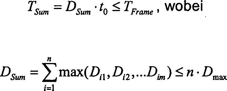
Diese
Zeit TSum ist kleiner bzw. gleich der Gesamtzeit
TFrame und kann auf TFrame ausgedehnt
werden, indem der Betriebsstrom I0 auf den
Betriebsstrom I1 reduziert wird. Der Betriebsstrom
I1, der der gewünschten Helligkeit angepasst
ist, ergibt sich aus: 
Der reduzierte Betriebsstrom Ii wird also dadurch erreicht, dass die aktive bzw. selektierte Phase einer Zeile (Zeilenadressierzeit ti) nicht fest an tL gebunden ist. Statt dessen bleibt jede Zeile i nur solange aktiv, wie es das hellste Pixel ij mit der Helligkeit Di max auf dieser Zeile erfordert. Wenn die erforderliche Zeit für das hellste Pixel erreicht ist, wird sofort auf die nächste Zeile umgeschaltet.The reduced operating current I i is thus achieved in that the active or selected phase of a line (line addressing time t i ) is not firmly bound to t L. Instead, each row i remains active only as long as it requires the brightest pixel ij with the brightness D i max on that row. When the required time for the brightest pixel is reached, the system switches to the next line immediately.
Mit
diesem zeitoptimierten Steuerverfahren sind der Betriebsstrom I1 und der Zeittakt für die Zeilenadressierung ti erfindungsgemäß variabel. Der Betriebsstrom
wird auf I1 reduziert und der Zeittakt für genau
ein Bit an Helligkeit (LSB, least significant bit) von t0 auf t1 erhöht: 
Ein
einfaches Beispiel wird hierfür
ist in
Die Matrix D repräsentiert drei helle Streifen mit je einem dazwischenliegenden dunklen Streifen, wobei der Einfachheit halber Grausstufen bis 3-Bit, d. h. eine maximale Helligkeit von Dmax = 7, angenommen werden. Insgesamt enthält die Matrixanzeige D also fünf Zeilen und drei Spalten.The matrix D represents three bright stripes, each with an intermediate dark stripe, for the sake of simplicity gray levels up to 3 bits, ie a maximum brightness of D max = 7, are assumed. Overall, the matrix display D thus contains five rows and three columns.
In
den
Während bei
der Single-Line-Adressierung (
Der
für die
Ansteuerung der gesamten Matrix D in gleicher Weise verwendete Betriebsstrom
I1 und der Zeittakt t1 für genau
ein Bit an Helligkeit sind nun abhängig von dem jeweils darzustellenden
Bild. Da bei Passiv-Matrix-OLEDs der Diodenstrom aufgrund des Multiplex-Verfahrens
recht hoch ist, ist die Quanteneffizienz bzw. die Leuchtintensität pro Stromeinheit
relativ gering. Bei reduziertem Betriebsstrom steigt die Quanteneffizienz,
was zu einem weiter reduzierten Betriebsstrom führen kann: 
η(I) ist die Quanteneffizienz bei dem Strom I in der Einheit Cd/A. Der Verlauf der Quanteneffizienz wird in einer Gamma-Tabelle abgespeichert und kann durch eine erfindungsgemäße Ansteuerelektronik, welche das beschriebene Verfahren umsetzt, für die obige Berechnung herangezogen werden.η is (I) the quantum efficiency at the current I in the unit Cd / A. The history the quantum efficiency is stored in a gamma table and can by an inventive control electronics, which implements the described method, used for the above calculation become.
Da der Betriebsstrom I1 gegenüber einer bekannten Ansteuerung reduziert ist, sinkt auch die Flussspannung der OLED-Dioden. Dadurch steigt auch der Wirkungsgrad mit der Einheit Lm/W, da die verbrauchte Energie gleich der Integra tion des Produktes von Strom und Spannung über die Frame-Periode ist. Der erreichte höhere Wirkungsgrad bedeutet auch eine geringere Eigenerwärmung des Displays, was zu einer Erhöhung der Display-Lebensdauer führt.Since the operating current I 1 is reduced compared to a known control, the forward voltage of the OLED diodes also decreases. As a result, the efficiency increases with the unit Lm / W, since the consumed energy is equal to the integration of the product of current and voltage over the frame period. The achieved higher efficiency also means less self-heating of the display, which leads to an increase in the display life.
Der Umsetzungsaufwand ist hierfür gering, weil der Betriebsstrom I1 für das Display nur einmal festgelegt werden muss und ein Zeittakt t1 leicht zu implementieren ist.The implementation effort is low, because the operating current I 1 for the display must be set only once and a time t 1 is easy to implement.
Bei der vorbeschriebenen Variante der Ansteuerung ist die Summe DSum der maximalen Helligkeiten D'max einer Zeile eine vorgegebene, nicht veränderbare Größe. Wenn mehrere Zeilen zusammengefasst und in einer Matrix gleichzeitig angesteuert werden, gibt es die Möglichkeit, DSum zu minimieren bzw. weiter zu verkleinern. Während einer Zeilenadressierzeit ti werden dann mehrere Zeilen gleichzeitig selektiert, so dass die erforderliche Zeit für die Ansteuerung der gesamten Bildmatrix insgesamt reduziert werden kann. Damit kann auch der Betriebsstrom weiter reduziert werden.In the above-described variant of the control, the sum D Sum of the maximum brightnesses D ' max of a line a predetermined, unchangeable size. If several lines are combined and controlled in one matrix at the same time, there is the possibility to minimize or reduce D Sum . During a line addressing time t i , several lines are then selected at the same time, so that the total time required to drive the entire picture matrix can be reduced as a whole. Thus, the operating current can be further reduced.
In
Diese Betrachtungsweise gilt auch, wenn mehr als zwei Zeilen gleichzeitig adressiert werden. Die Zeiteinsparung ist umso größer, je mehr Zeilen zusammengefasst werden. Dies ist eine dann Multi-Line-Adressierung.These Viewing is also true if more than two lines at the same time be addressed. The time savings are the greater, depending more lines are summarized. This is then a multi-line addressing.
Die Zusammenfassung mehrerer Zeilen ist jedoch nicht ohne Weiteres möglich, da nun mehrere Pixel einer Spalte in mehreren Zeilen gleich angesteuert werden. Es gibt in der Helligkeit also keinen Unterschied zwischen diesen Pixeln mehr, so dass differentielle Informationen verloren gehen bzw. die Auflösung reduziert wird.The Summary of several lines, however, is not readily possible since Now several pixels of a column in several lines are controlled the same become. There is no difference in brightness between these pixels more so that differential information is lost go or the resolution is reduced.
Dieses
Problem wird dadurch gelöst,
dass die Multi-Line-Adressierung (MLA) mit der zuvor beschriebenen,
optimierten Improved-Single-Eine-Adressierung (ISLA) kombiniert
wird, indem die gewünschte
Matrixanzeige D in mehrere Matrizen zerlegt wird. Das heißt, dass
eine Zeile in verschiedenen Matrizen S, M sowohl alleine als auch
mit anderen Zeilen gemeinsam adressiert wird. Der Unterschied in
der Leuchtintensität
zwischen den Pixeln in den verschiedenen, in der Multi-Line-Adressierung
aber gemeinsam angesteuerten Zeilen der jeweiligen Spalte wird durch
die Improved-Single-Eine-Adressierung mit der Matrix S realisiert.
Die Multi-Eine-Adressierung soll die erforderlichen Gesamtzeit TSum minimieren. Die Überführung einer Matrixanzeige D
in eine Single-Eine-Matrix S und Multi-Eine-Matrix M wird mathematisch
wie folgt dargestellt.
Die Quellendaten für die einzelnen Pixelhelligkeiten Dij der Matrixanzeige D, welche zu dem gewünschten Bild zusammengesetzt werden, werden in zwei Matrizen S und M2 zerlegt. S ist die Single-Eine-Matrix, die durch die Improved-Single-Line-Adressierung angesteuert wird. M2 ist die Multi-Line-Matrix, für deren Ansteuerung jeweils zwei Zeilen zusammengefasst und gemeinsam adres siert bzw. aktiviert werden. Die Darstellung von M2 in n – 1 Matrizen, wobei n die Anzahl der Zeilen der Matrixanzeige D ist, zeigt, dass für jede dieser Matrizen M zwei Zeilen zusammengefasst werden, da die Einträge in den zwei Zeilen identisch sind. Die Zusammenfassung zweier Zeilen wird vorzugsweise für zwei aufeinander folgende Zeilen vorgenommen, weil angenommen wird, dass aufeinander folgende Zeilen eines Bildes die größten Ähnlichkeiten besitzen und die Verteilung der zweifachen Betriebsströme in zwei Pixel bei aufeinander folgenden Zeilen eines reellen Displays am homogensten ist. Zudem ist die mathematische Zerlegung für diese Einschränkung einfacher als wenn zwei beliebige Zeilen zusammengefasst werden. Die Implementierung der Algorithmen ist dann von geringerem Aufwand und wird weiter unten in einer erfindungsgemäßen Realisierung noch genauer beschrieben.The source data for the individual pixel brightnesses D ij of the matrix display D, which are assembled into the desired image, are decomposed into two matrices S and M2. S is the single-A matrix, which is driven by the Improved single-line addressing. M2 is the multi-line matrix, for the activation of which two lines are combined and jointly addressed or activated. The representation of M2 in n-1 matrices, where n is the number of rows of the matrix display D, shows that for each of these matrices M, two rows are combined since the entries in the two rows are identical. The merging of two lines is preferably done for two consecutive lines, because it is assumed that successive lines of an image have the greatest similarities and the distribution of the two-fold operating currents in two pixels is most homogeneous in successive lines of a real display. In addition, mathematical decomposition is easier for this constraint than when two arbitrary rows are combined. The implementation of the algorithms is then of less effort and will be described in more detail below in an implementation according to the invention.
Natürlich können je nach Anwendung auch nicht benachbarte Zeilen zusammengefasst werden. Bspw. können mit der Zusammenfassung von zwei durch eine Zwischenzeile voneinander getrennte Zeilen Schachbrettmuster sehr gut mit der Multi-Line-Adressierung abgebildet werden.Of course you can ever After application also not adjacent rows are summarized. For example. can with the summary of two by an intermediate line from each other separate rows checkerboard pattern very well with the multi-line addressing be imaged.
Die
Zeilenadressierzeit ti, die jede „Zweizeile" für die Aktivierung
bekommt, hängt
analog zu der vorbeschriebenen Realisierung von der maximalen Helligkeit
Mij eines Pixels in dieser Zweizeile ab.
Das zeitoptimierte Ansteuerverfahren, das bereits für die Single-Line-Adressierung
beschrieben wurde, wird auch hier eingesetzt. Die Summe der Zeilenadressierzeiten
ergibt sich also wie folgt: 
Das Ziel der Zerlegung in mehrere Matrizen ist eine weitere Reduktion des Betriebsstroms I1, d. h. eine Minimierung von DSum. Das wird erreicht, indem jede Helligkeit M2ij der Multi-Line-Matrix M2 zwei Elemente in der Single-Line-Matrix, nämlich Sij und Si+1,j um den Betrag M2ij von der Originaldaten Dij und Di+1,j reduziert. Dafür wird jedoch nur eine Zeilenadressierzeit ti benötigt, nämlich die Zeit für die Adressierung von M2ij. Bei mehreren Zeilen ist die Wirkung entsprechend höher.The goal of decomposing into multiple matrices is a further reduction of the operating current I 1 , ie a minimization of D Sum . This is achieved by dividing each brightness M2 ij of the multi-line matrix M2 into two elements in the single-line matrix, namely S ij and S i + 1, j by the amount M2 ij from the original data D ij and D i + 1, j reduced. However, only one row addressing time t i is required, namely the time for the addressing of M2 ij . With several lines the effect is correspondingly higher.
Die
Transformation der Quellendaten (Matrixanzeige D) in mehrere Multi-Line-Matrizen wird analog durch
Es
ist auch möglich,
manche Multi-Line-Matrizen auszulassen, bspw. gemäß der Definition
Die Idee, ein Bild bzw. eine Bildmatrix D in mehrere Bilder respektive Bildmatrizen S, M aufzuteilen, die leichter anzusteuern sind, kann für alle Matrix-Display-Arten, einschließlich LCD- und Plasma-Displays, angewendet werden. Die Multi-Line-Matrix ist ein gutes Beispiel für eine einfache und effiziente Ansteuerung.The Idea, an image or an image matrix D into several images respectively Splitting image matrices S, M, which are easier to control for all Matrix display types, including LCD and plasma displays, to be applied. The multi-line matrix is one good example for a simple and efficient control.
Nachfolgend
wird eine vollständige
Multi-Line-Adressierung einschließlich einer Single-Line-Adressierung
an einem konkreten Beispiel beschrieben. Das Ziel der vorgenommenen
Transformationen ist dabei die Minimierung von Dsum . Das Ergebnis ist, dass der Betriebsstrom
nicht mehr I0 ist, sondern (bildabhängig) deutlich
kleiner werden kann: 
Bei
dem in
Die
erste Matrix in
Wenn
eine Dreizeilen-Matrix-Adressierung M3 entsprechend
In
In
dem dargestellten Beispiel beträgt
der Betriebsstrom I0 für die konventionelle Single-Line-Adressierung
100 μA.
Entsprechend der Reduktion auf 53% beträgt der Betriebsstrom bei einer
Ansteuerung einer Zeile also I1 = 53 μA ist. Die
Flussspannung der OLED bei 53 μA
beträgt
6 V. Die Schwellenspannung der OLED beträgt 3 V. Eine Frame-Periode,
d. h. die Gesamtzeit TFrame , beträgt 13,5
msec. Bei der konventionellen Single-Line-Adressierung beträgt die konstante
Zeilenadressierzeit t0 = 0,1 msec. Mit der
Multi-Line-Adressierung entsprechend
Die S-Matrix und M2-Matrix werden abwechselnd aktiviert. Es wird zuerst die erste Zeile der S-Matrix adressiert, dann die erste Zweizeile der M2-Matrix (d. h. deren Zeilen 1 und 2), dann die zweite Zeile der S-Matrix, dann die zweite Zweizeile der M2-Matrix (d. h. deren Zeilen 2 und 3), usw..The S matrix and M2 matrix are activated alternately. It will be first the first line of the S-matrix addressed, then the first two-line the M2 matrix (i.e., its rows 1 and 2), then the second row the S-matrix, then the second two-row of the M2 matrix (i.e. Lines 2 and 3), etc ..
In
In
Die Zeitspanne (Zeilenadressierzeit ti), in der die achte Zeile aktiviert ist, besteht aus drei Phasen. Während der ersten vier Takte (von 9,375 msec bis 10,125 msec) sind Zeile 7 und Zeile 8 gemeinsam adressiert. Der Strom beträgt daher auch 2·53 μA. Das entspricht der Zeilenadressierung von M272.The time span (line addressing time t i ) in which the eighth line is activated consists of three phases. During the first four bars (from 9.375 msec to 10.125 msec) row 7 and row 8 are addressed together. The current is therefore also 2 x 53 μA. This corresponds to the row addressing of M272.
In den nächsten fünf Takten wird die Zeile 8 von S82 adressiert. Die insgesamt fünf Takte der Zeilenadressierzeit ti kommen daher, dass das Maximum der Helligkeit Sij der achten Zeile der Matrix S den Wert 5 hat (siehe 1. Spalte, 8. Zeile). Es fließt ein Strom von 53 μA für eine Zeit von 0,1875 msec (ein Takt). Dann ist der Strom für vier weitere Takte Null, da das Maximum der achten Zeile der S-Matrix (S81) 5 beträgt und die Helligkeitssteuerung durch eine Pulsweitenmodulation vorgenommen wird.In the next five bars, line 8 is addressed by S 82 . The total of five bars of the row addressing time t i come from the fact that the maximum of the brightness Sij of the eighth row of the matrix S has the value 5 (see 1st column, 8th row). A current of 53 μA flows for a time of 0.1875 msec (one clock). Then, the current for four more clocks is zero, since the maximum of the eighth row of the S matrix (S 81 ) is 5 and the brightness control is performed by a pulse width modulation.
Die letzte Phase dauert 5 Takte, in der die achte und der neunte Zeile der Matrix M2 adressiert sind. Der Strom beträgt wieder 106 μA. Der Strom fließt jedoch nur 4 Takte lang, da M282 4 beträgt. Der Strom sinkt für einen Takt wieder auf Null. In der dritten Spalte fließt auch in diesem letzten Takt noch Strom (nicht dargestellt), weil die maximale Helligkeit in der dritten Spalte M283 = 5 beträgt. Die gesamte Dauer, in der das Pixel ij = 82 mit Betriebsstrom beaufschlagt wird (aktiven Zeit) beträgt 9 Takte, was D82 entspricht.The last phase lasts 5 bars, in which the eighth and ninth rows of the matrix M2 are addressed. The current is again 106 μA. However, the current only flows for 4 cycles, since M2 82 is 4. The current drops back to zero for one cycle. Current (not shown) also flows in the third column in this last cycle because the maximum brightness in the third column M2 is 83 = 5. The total duration in which the pixel ij = 82 is supplied with operating current (active time) is 9 clocks, which corresponds to D 82 .
Die
Spannung in der zweiten Spalte ist in
In
Die technische Realisierung des erfindungsgemäßen Verfahrens zur Ansteuerung von Matrixanzeigen ist ähnlich einfach wie bei konventionellen Single-Line-Adressierungs-Verfahren. An jeder Zeile befindet sich ein Schalter und jede Spalte ist mit einer Stromquelle versehen, die bei einer Zwei-Zeilen-Adressierung drei Stromstufen (wie 0, 1 und 2) aufweist, während es bei einem konventionellem Single-Line-Adressierungs-Verfahren nur zwei Stufen (wie 0 und 1) gibt. Dies liegt daran, dass bei der gleichzeitigen Adressierung von mehreren Zeilen der entsprechend erhöhte Strom verfügbar sein muss. Allgemein gilt, dass bei einer gleichzeitigen Adressierung von n Zeilen eine Abstufung mit n + 1 Stufen erforderlich ist. Dies ist jedoch mit einem geringen Aufwand zu realisieren. Eine konkrete Schaltung für eine gemischte Amplituden-Pulsweiten-Modulation zur Helligkeitssteuerung wird später noch genauer beschrieben.The technical realization of the method according to the invention for driving matrix displays is similarly simple as in conventional single-line addressing methods. There is one switch on each row and each column is provided with a current source having three current levels (such as 0, 1 and 2) for two-line addressing, compared to only two in a conventional single-line addressing method Steps (like 0 and 1) exist. This is because with the simultaneous addressing of several lines, the correspondingly increased current must be available. As a general rule, if n lines are addressed at the same time, grading with n + 1 levels is required. However, this is a small one To realize effort. A concrete circuit for a mixed amplitude-pulse width modulation for brightness control will be described later in more detail.
In dem vorbeschriebenen Beispiel wurde eine Pulsweitenmodulation des Betriebsstroms verwendet. Natürlich können die S- und die M2-Matrizen auch durch eine Amplitudenmodulation des Betriebesstroms abgebildet werden. Bei der Amplitudenmodulation wird jede Zeile bzw. jede Mehrzeile wird so lange adressiert, wie es dem Maximum auf dieser Zeile bzw. Mehrzeile entspricht. Das ist bei der Pulsweitenmodulation gleich. Der einzige Unterschied besteht darin, dass der Betriebsstrom während der Zeilenadressierungszeit ti ständig fließt und die Höhe seiner Amplitude angepasst wird.In the example described above, a pulse width modulation of the operating current was used. Of course, the S and M2 arrays can also be mapped by amplitude modulation of the operating current. In the case of amplitude modulation, each line or multiple line is addressed as long as it corresponds to the maximum on this line or multiple line. This is the same with pulse width modulation. The only difference is that the operating current flows continuously during the row addressing time t i and the magnitude of its amplitude is adjusted.
Damit der Betriebsstrom minimiert wird, ist die optimierte und effiziente Überführung der Quellenmatrix (Matrixanzeige D) in Multi-Line-Matrizen M und eine Single-Line-Matrix S entscheidend. Optimiert bedeutet eine Minimierung der Summe der maximalen Helligkeiten DSum und effizient bedeutet eine mit geringem Hardware-Aufwand und schnell durchführbare Überführung.In order to minimize the operating current, the optimized and efficient transfer of the source matrix (matrix display D) into multi-line matrices M and a single-line matrix S is decisive. Optimized means minimizing the sum of the maximum magnitudes D Sum and efficiently means a low hardware overhead and fast turnaround.
Die Gewinnung bzw. Bestimmung der Matrizen M und S ist grundsätzlich mit bekannten Methoden wie Linearer Programmierung und mit Standard-Software durchführbar. Allerdings müssen dann aufwendige arithmetische Operationen, wie Multiplikation und Division, angewendet werden, so dass diese Methode sehr rechenintensiv und langsam ist. Außerdem steigt die Komplexität mehr als quadratisch mit der Größe der Bildmatrix an.The Obtaining or determining the matrices M and S is basically with well-known methods like linear programming and with standard software feasible. However, you have to then complex arithmetic operations, such as multiplication and Division, be applied, making this method very computationally intensive and is slow. Furthermore the complexity increases more than square with the size of the image matrix at.
Daher
wird erfindungsgemäß eine kombinatorische
Methode vorgeschlagen, die auf dem sogenannten "MaxFlow/MinCut"-Prinzip beruht. Da die Güte des Optimums
im Wesentlichen davon abhängt,
wie sich zwei aufeinander folgende Zeilen unterscheiden, wird die
Nebenbedingung D = S + M2 + M3 + ... umgeformt, indem die Differenz
zweier aufeinander folgender Gleichungen gebildet wird, ohne dabei
den Lösungsraum
zu verändern.
Dabei entstehen die Matrizen d',
S' und M2', M3', wie in
Die
umgeformten Nebenbedingungen lassen sich durch den in
Hierbei
stellt jeder als Kreis dargestellter Knoten (aus einer Knotenmenge
V) einen Eintrag in der umgeformten Matrix d' dar. d'ij im Kreis
repräsentiert
das entsprechende Element der Matrix d', die in
Dies
wird nachfolgend anhand des bereits in den
Jedes Element der d'-Matrix entspricht einem Knoten in der entsprechenden Position. Die Kanten sind noch alle mit Null belegt, da es hier um den Start der Matrixzerlegung handelt. Eine gültige Zerlegung ist genau dann erreicht, wenn die Summe der Belegungen (Zahlen) der ausgehenden Kanten (von dem Kreis ausgehenden Pfeile) minus der Summe der Belegungen (Zahlen) der eingehen den Kanten (an dem Kreis ankommende Pfeile) jeden Knotens (Kreises) gleich seines jeweiligen Wertes (Bedarf) der Knotens ist. Dabei sind alle Kantenbelegungen nicht negativ.each Element of the d'matrix corresponds to a node in the corresponding position. The edges are still all zeroed, since this is the start of the matrix decomposition is. A valid one Decomposition is achieved exactly when the sum of the assignments (Numbers) of the outgoing edges (arrows starting from the circle) minus the sum of the assignments (numbers) of the incoming edges (at the circle arriving arrows) of each node (circle) equal to its respective value (need) of the node. Here are all edge assignments not negative.
In
Nachfolgend
wird das mathematische Verfahren genauer beschrieben, mit dem der
in
Zwei
Kanten (Pfeile) in 


Die vorgenannte Aufgabe ist äquivalent zu dem Problem, jedem Kantentyp Ak, k = 1,...,p eine nichtnegative Zahl (eine sogenannte Kapazität) zuzuordnen, so dass die Summe dieser Kapazitäten minimal ist und eine gültige Belegung der Kanten existiert, welche die Kapazitäten nicht überschreitet.The above object is equivalent to the problem of assigning to each edge type A k , k = 1,..., P a nonnegative number (a so-called capacitance) such that the sum of these capacitances is minimal and there exists a valid occupancy of the edges does not exceed the capacities.
Das Besondere an diesem neuen Verfahren ist, dass die Kapazität für alle Kanten einer bestimmten Länge einer Zeile gültig ist. Der Fluss auf jeder dieser Kanten ist kleiner oder gleich dieser Kapazität. Die Kapazitäten selbst sind variabel und stellen in gewisser Weise die Kosten bzw. den Aufwand für die Optimierung dar. Die Summe aller Kapazitäten muss minimiert werden. Im Gegensatz zu einer bekannten Max-Flow/Min-Cut Methode, bei der bei gegebenen Kapazitäten der Fluss maximiert wird, wird hier bei gegebenem Fluss die Kapazität minimiert.The Special about this new procedure is that the capacity for all edges a certain length valid for one line is. The flow on each of these edges is less than or equal to this Capacity. The capacities themselves are variable and in some ways cost or the effort for the optimization. The sum of all capacities must be minimized. Unlike a known max-flow / min-cut method, in which given capacities When the flow is maximized, the capacity is minimized for a given flow.
Die Kapazitäten sind eine Funktion u: {1,..., p} → Z≥0C, so dass für alle k ∊ {1,..., p} und a ∊ Ak gilt: f(a) ≤ u(k).The capacities are a function u: {1, ..., p} → Z ≥0C , so that for all k ∈ {1, ..., p} and a ∈ A k : f (a) ≤ u ( k).
Die vorbeschriebene Minimierung lässt sich grundsätzlich auch als lineares Programm modellieren und lösen, was jedoch wie bereits erwähnt sehr rechenintensiv ist. Wie nachfolgend gezeigt lässt sich das vorbeschriebene, erfindungsgemäße Verfahren mit nur geringem Aufwand mathematisch wie folgt umsetzen.The previously described minimization basically as a linear program model and solve, but as already mentioned is very computationally intensive. As shown below the above-described, inventive method with only a small Mathematically implement the effort as follows.
Dazu werden die Kapazitäten sukzessive, d. h. schrittweise, von Null an erhöht, bis eine gültige Zerlegung möglich ist. Damit wird auch sichergestellt, dass die Kapazität größer oder gleich Null ist. Dabei wird in jeder Iteration die Menge an Kanten bestimmt, deren Belegung gleich der Kapazität ist und somit einen Flaschenhals darstellt, der eine gültige Lösung verhindert. Diese Kantenmenge, auch minimaler Schnitt genannt, trennt die Knoten mit positivem Bedarf von denen mit negativen Bedarf. Danach werden die Kapazitäten der Kanten aus dem minimalen Schnitt erhöht. Vorzugsweise geschieht dies aber nur für die Kapazität, die es den meisten Kanten erlaubt, den Flaschenhals zu verlassen. Die Belegungen werden nun so weit erhöht, bis entweder eine gültige Lösung gefunden ist oder ein erneuter Flaschenhals auftritt, woraufhin die beschriebenen Schritte wiederholt werden.To become the capacities successively, d. H. incrementally, increasing from zero until a valid decomposition possible is. This will also ensure that the capacity is greater or greater is equal to zero. In each iteration, the amount of edges determined, whose occupancy is equal to the capacity and thus a bottleneck represents a valid one solution prevented. This set of edges, also called minimum cut, separates the nodes with positive needs of those with negative needs. After that, the capacity will be the edges increased from the minimum cut. Preferably happens but only for the capacity, which allows most edges to leave the bottleneck. The assignments are now increased until either a valid solution is found or a new bottleneck occurs, following which the steps described be repeated.
Eine
mathematische Formulierung des Verfahrensablaufs ist 
Das Verfahren dieser Erfindung kann natürlich auch für einen Teilbereich einer Bildmatrix eingesetzt werden. So kann ein Bild in mehrere Segmente aufgeteilt und jedes für sich optimiert werden, was einer lokalen Optimierung entspricht.The Of course, the method of this invention can also be applied to one Subarea of an image matrix can be used. So can a picture divided into several segments and each optimized for what corresponds to a local optimization.
Ebenso kann eine gemischte globale und lokale Optimierung durchgeführt werden, indem ein Segment bestimmter Größe zeilenweise oder um mehrere Zeilen verschoben wird. Die Submatrix wird gebildet aus einer bestimmten Anzahl von Zeilen. Sie wird zuerst aus den oberen Zeilen der Quellenmatrix gebildet. Bei jeder Optimierung werden die Matrixeinträge (S, M2, M3 etc.) für die oberste Zeile oder wenige oberste Zeilen gewonnen. Die nächste Submatrix wird dementsprechend um eine oder mehrere Zeile nach unten verschoben. Der Einfluss der zuvor gewonnenen Multi-Line-Matrix-Zeile auf diese neue Submatrix muss abgezogen werden. Dann werden wieder eine oder mehrere Zeilen von S, M2, M3 etc. gewonnen. Die Submatrix läuft bis zum Ende der Quellenmatrix und wird dann komplett zerlegt. Damit erhält man alle Einträge von S, M2, M3 etc..As well a mixed global and local optimization can be done by placing a segment of specific size line by line or moved by several lines. The submatrix is formed from a certain number of lines. She gets out of the first formed upper rows of the source matrix. At every optimization become the matrix entries (S, M2, M3 etc.) for won the top line or a few top lines. The next submatrix is accordingly shifted down by one or more lines. The influence of the previously obtained multi-line matrix line on this new submatrix must be subtracted. Then again one or several lines of S, M2, M3 etc. won. The submatrix runs until the End of the source matrix and is then completely decomposed. This gives you all Posts from S, M2, M3 etc.
Die Zerlegung einer kleineren Matrix erfordert weniger Speicherplatz und weniger Iterationen. Bei einer globaler Optimierung, bei der die Matrix in der Regel groß ist, muss das Ergebnis der Matrix-Zerlegung in einen Zwischenspeicher, wie SRAM oder dgl., abgelegt werden. Erst unmittelbar vor der Aktivierung werden die Informationen dann zeilenweise in Register für den Ausgangstreiber eingelesen. Bei segmentierter/lokaler bzw. gemischter Optimierung können die Kapazitäten zuerst durch die Submatrix-Zerlegung gewonnen, folglich auch deren Summe, bzw. t1 und I1. Dank der schnellen Zerlegung wird dann sukzessiv das Zeilenergebnis noch einmal berechnet und direkt dem Register für den Ausgangstreiber weitergereicht, so dass der große Zwischenspeicher entfallen kann. Der Hardware-Aufwand kann durch die segmentierte/lokale bzw. gemischte Optimierung reduziert werden, während die Güte der Optimierung in diesem Fall etwas abnehmen kann.The decomposition of a smaller matrix requires less memory and fewer iterations. In a global optimization, where the matrix is typically large, the result of the matrix decomposition must be placed in a cache, such as SRAM or the like. Only immediately before activation, the information is then read line by line in register for the output driver. In the case of segmented / local or mixed optimization, the capacitances can first be obtained by the sub-matrix decomposition, and consequently also their sum, or t 1 and I 1 , respectively. Thanks to the fast decomposition, the row result is then successively calculated again and passed on directly to the register for the output driver, so that the large buffer can be dispensed with. The hardware overhead can be reduced by the segmented / local or mixed optimization, while the quality of the optimization can decrease somewhat in this case.
Wenn die Matrizen M, S mit den den einzelnen Pixeln ij entsprechenden Helligkeiten feststehen, müssen die Dioden entsprechend angesteuert werden. Die einzelnen Zeilenadressierzeiten ti können von Zeile zu Zeilen variieren und richten sich jeweils nach dem maximalen Helligkeitswert dieser Zeilen. Die Helligkeitssteuerung kann dann durch eine Pulsweitenmodulation bzw. eine Amplitudenmodulation des Strom erreicht werden.If the matrices M, S are fixed with the brightnesses corresponding to the individual pixels ij, the diodes must be driven accordingly. The individual Zeilenadressierzeiten t i can vary from line to line and are each based on the maximum brightness value of these lines. The brightness control can then be achieved by a pulse width modulation or an amplitude modulation of the current.
Bei der Pulsweitenmodulation werden nur die Pixel ij mit der maximalen Helligkeit während der gesamten Zeilenadressierzeit angeschaltet, d. h. von dem Betriebsstrom durchflossen. Die übrigen Pixel ij leuchten nur zeitweise, wobei die jeweilige Leuchtzeit mit dem jeweiligen Helligkeitswert Sij, Mij korreliert ist.at the pulse width modulation only the pixels ij with the maximum Brightness during turned on the entire Zeilenadressierzeit, d. H. from the operating current traversed. The remaining Pixel ij light only temporarily, with the respective lighting time is correlated with the respective brightness value Sij, Mij.
Alternativ kann auch eine Amplitudenmodulation zur Helligkeitssteuerung eingesetzt werden, so dass alle Pixel ij in der aktiven Phase, d. h. während der jeweiligen Zeilenadressierzeit ti, zu 100% der Zeit eingeschaltet sind und der Betriebsstrom bei Pixeln ij mit geringerer Helligkeit entsprechend verkleinert ist. Allerdings ist die Amplitudenmodulation in Bezug auf die Hardware schwieriger zu implementieren. Dies gilt insbesondere für eine hohe Farbtiefe bzw. viele Graustufen, während eine Pulsweitenmodulation vergleichsweise einfach und genau implementierbar ist, ohne dass ein hoher Aufwand für die eingesetzte Hardware erforderlich ist.Alternatively, an amplitude modulation can be used for brightness control, so that all pixel ij in the active phase, that is during the respective row addressing time t i, are switched to 100% of the time and the operating current at pixels ij is correspondingly reduced with lower brightness. However, amplitude modulation is harder to implement in terms of hardware. This is especially true for a high color depth or many gray levels, while a pulse width modulation is comparatively simple and accurate to implement without a high cost of the hardware used is required.
Besonders
vorteilhaft ist es, eine Pulsweitenmodulation mit einer Amplitudenmodulation
zu kombinieren, um den Betriebsstrom bei Pixeln ij mit geringerer
Helligkeit zu reduzieren. Diese erfindungsgemäße gemischte bzw. kombinierte
Amplituden- und Pulsweitenmodulation wird nachfolgend mit Bezug
auf die
Für die vorbeschriebene Multi-Line-Adressierung gemäß der Erfindung muss der Betriebsstrom quantifiziert, d. h. in mehrere verschiedene Stufen eingeteilt, werden, um die Ströme für Ein-, Zwei- und Mehrzeilenadressierung in die Spalten einzuspeisen und die Höhe des Stroms dementsprechend einzustellen. Beispielsweise muss für vier gleichzeitig angesteuerte Zeilen bei einer Multi-Line-Adressierung M4 auch der vierfache Betriebsstrom (4·I1) eingeprägt werden.For the above-described multi-line addressing according to the invention, the operating current must be quantified, ie divided into several different stages, fed to the streams for one, two and more lines addressing in the columns and adjust the amount of current accordingly. For example, for four lines addressed simultaneously, the fourfold operating current (4 * I 1 ) must also be impressed in a multi-line addressing M4.
Dazu
kann die Stromquelle mit drei Transistoren, wie in
Der
quantifizierte Betriebsstrom kann auch genutzt werden, um den Betriebsstrom
bei einem Matrix-Eintrag, dessen Helligkeitswert Mij,
Sij nicht ein Maximum ist, abermals zu reduzieren.
Dazu kann bspw. der in
Das
Ergebnis dieser kombinierten Helligkeitssteuerung ist in
Es
ist in
Natürlich können auch
nur Teile der obigen, in
Mit dem vorliegenden Verfahren zur Ansteuerung von Matrixanzeigen und einer zur Durchführung des zuvor beschriebenen Verfahrens eingerichteten Displaysteuerung, auf welche sich die Erfindung auch bezieht, ist es also möglich, eine optimierte Ansteuerung von Matrixanzeigen zu erreichen. Diese kann zur Performancesteigerung, bspw. einer erhöhten Bildwiederholfrequenz, und/oder zur Reduzierung des für die Ansteuerung der einzelnen Pixel erforderlichen Betriebsstroms verwendet werden. Wesentliche Merkmale sind dabei, dass die Zeilenadressierzeit für jede Zeile in Abhängigkeit von der maximalen Helligkeit, die ein Pixel in dieser Zeile erreichen muss, abhängt und/oder die Matrixanzeige in mehrere separate Matrizen zerlegt wird, von denen einige eine Mehr- oder Multizeilenansteuerung repräsentieren.With the present method for driving matrix displays and one for implementation the display control set up as described above, to which the invention also relates, it is thus possible to have a to achieve optimized control of matrix displays. This can for increasing the performance, for example an increased refresh rate, and / or to reduce the for the control of the individual pixels required operating current be used. Essential features are that the Zeilenadressierzeit for every Line in dependence from the maximum brightness that a pixel in that row can reach must, depends and / or decomposing the matrix display into a plurality of separate matrices some of which represent multi-or multi-line control.
Die vorliegende Erfindung bezieht sich auch auf eine Steuerung zur Durchführung des vorbeschriebenen Verfahrens. Dazu kann das beanspruchte Verfahren in einem anwendungsspezifischen IC (ASIC), wenn bspw. der Display-Controller und der Displaytreiber in einem Chip integriert sind, implementiert sein. Die Erzeugung von t1 und I1 geschieht in dem Treiber. Die Matrix-Zerlegung wird mit einer kombinatorischen Logik realisiert, die einfach und schnell ist.The present invention also relates to a controller for carrying out the above-described method. For this purpose, the claimed method can be implemented in an application-specific IC (ASIC) if, for example, the display controller and the display driver are integrated in one chip. The generation of t 1 and I 1 happens in the driver. Matrix decomposition is realized with combinational logic that is simple and fast.
Da ein Bild und folglich auch die abgeleiteten Matrizen immer datenintensiv sind, wird ferner Speicher benötigt. Dieser Bedarf kann mit einem modernen Halbleiterprozess oder wie vorbeschrieben auch mit lokaler bzw. gemischter Optimierung reduziert werden. Natürlich kann das vorliegende Verfahren auch auf mehreren Chips aufgeteilt werden.There a picture and consequently also the derived matrices are always data intensive memory is also required. This need can be with a modern semiconductor process or how previously described also reduced with local or mixed optimization become. Naturally For example, the present method can be divided into multiple chips become.
Claims (22)
Priority Applications (6)
| Application Number | Priority Date | Filing Date | Title |
|---|---|---|---|
| DE102005063159A DE102005063159B4 (en) | 2005-12-30 | 2005-12-30 | Method for controlling matrix displays |
| JP2008547884A JP5313687B2 (en) | 2005-12-30 | 2006-12-21 | Matrix display driving method, self-luminous display, non-self-luminous display, and display control system |
| EP06841084.4A EP1966786B1 (en) | 2005-12-30 | 2006-12-21 | Method for triggering matrix displays |
| CN2006800499649A CN101366069B (en) | 2005-12-30 | 2006-12-21 | Method for triggering matrix displays |
| PCT/EP2006/012362 WO2007079947A1 (en) | 2005-12-30 | 2006-12-21 | Method for triggering matrix displays |
| US12/163,083 US8456493B2 (en) | 2005-12-30 | 2008-06-27 | Method for driving matrix displays |
Applications Claiming Priority (1)
| Application Number | Priority Date | Filing Date | Title |
|---|---|---|---|
| DE102005063159A DE102005063159B4 (en) | 2005-12-30 | 2005-12-30 | Method for controlling matrix displays |
Publications (2)
| Publication Number | Publication Date |
|---|---|
| DE102005063159A1 DE102005063159A1 (en) | 2007-07-05 |
| DE102005063159B4 true DE102005063159B4 (en) | 2009-05-07 |
Family
ID=37946342
Family Applications (1)
| Application Number | Title | Priority Date | Filing Date |
|---|---|---|---|
| DE102005063159A Expired - Fee Related DE102005063159B4 (en) | 2005-12-30 | 2005-12-30 | Method for controlling matrix displays |
Country Status (6)
| Country | Link |
|---|---|
| US (1) | US8456493B2 (en) |
| EP (1) | EP1966786B1 (en) |
| JP (1) | JP5313687B2 (en) |
| CN (1) | CN101366069B (en) |
| DE (1) | DE102005063159B4 (en) |
| WO (1) | WO2007079947A1 (en) |
Cited By (11)
| Publication number | Priority date | Publication date | Assignee | Title |
|---|---|---|---|---|
| US11156759B2 (en) | 2019-01-29 | 2021-10-26 | Osram Opto Semiconductors Gmbh | μ-LED, μ-LED device, display and method for the same |
| US11271143B2 (en) | 2019-01-29 | 2022-03-08 | Osram Opto Semiconductors Gmbh | μ-LED, μ-LED device, display and method for the same |
| US11302248B2 (en) | 2019-01-29 | 2022-04-12 | Osram Opto Semiconductors Gmbh | U-led, u-led device, display and method for the same |
| US11538852B2 (en) | 2019-04-23 | 2022-12-27 | Osram Opto Semiconductors Gmbh | μ-LED, μ-LED device, display and method for the same |
| US11610868B2 (en) | 2019-01-29 | 2023-03-21 | Osram Opto Semiconductors Gmbh | μ-LED, μ-LED device, display and method for the same |
| US12183261B2 (en) | 2019-01-29 | 2024-12-31 | Osram Opto Semiconductors Gmbh | Video wall, driver circuits, controls and method thereof |
| US12189280B2 (en) | 2019-05-23 | 2025-01-07 | Osram Opto Semiconductors Gmbh | Lighting arrangement, light guide arrangement and method |
| US12261256B2 (en) | 2019-02-11 | 2025-03-25 | Osram Opto Semiconductors Gmbh | Optoelectronic component, optoelectronic arrangement and method |
| US12266641B2 (en) | 2019-05-13 | 2025-04-01 | Osram Opto Semiconductors Gmbh | Multi-chip carrier structure |
| US12294039B2 (en) | 2019-09-20 | 2025-05-06 | Osram Opto Semiconductors Gmbh | Optoelectronic component, semiconductor structure and method |
| US12613423B2 (en) | 2019-05-14 | 2026-04-28 | Osram Opto Semiconductors Gmbh | Illumination unit, method for producing an illumination unit, converter element for an optoelectronic component, radiation source including an LED and a converter element, outcoupling structure, and optoelectronic device |
Families Citing this family (19)
| Publication number | Priority date | Publication date | Assignee | Title |
|---|---|---|---|---|
| GB2436390B (en) * | 2006-03-23 | 2011-06-29 | Cambridge Display Tech Ltd | Image processing systems |
| DE102008024126A1 (en) | 2008-05-19 | 2009-12-03 | X-Motive Gmbh | Method and driver for driving a passive matrix OLED display |
| US8610650B2 (en) | 2009-05-20 | 2013-12-17 | Dialog Semiconductor Gmbh | Advanced multi line addressing |
| EP2254109A1 (en) * | 2009-05-20 | 2010-11-24 | Dialog Semiconductor GmbH | Tagged multi line address driving |
| EP2254108A1 (en) * | 2009-05-20 | 2010-11-24 | Dialog Semiconductor GmbH | Extended multi line address driving |
| CN101714348B (en) * | 2009-12-22 | 2012-04-11 | 中国科学院长春光学精密机械与物理研究所 | Hybrid overlying gray-level control display drive circuit |
| CN102109719B (en) * | 2009-12-24 | 2012-06-27 | 晶宏半导体股份有限公司 | Method for driving liquid crystal display device based on four-line multi-line addressing technology |
| EP2511899A1 (en) * | 2011-04-13 | 2012-10-17 | Dialog Semiconductor GmbH | Methods and apparatus for driving matrix display panels |
| KR101824413B1 (en) | 2011-08-30 | 2018-02-02 | 삼성전자주식회사 | Method and apparatus for controlling operating mode of portable terminal |
| US10789892B2 (en) * | 2015-03-11 | 2020-09-29 | Facebook Technologies, Llc | Dynamic illumination persistence for organic light emitting diode display device |
| KR102599600B1 (en) | 2016-11-23 | 2023-11-07 | 삼성전자주식회사 | Display apparatus and driving method thereof |
| US10366674B1 (en) * | 2016-12-27 | 2019-07-30 | Facebook Technologies, Llc | Display calibration in electronic displays |
| CN107393471B (en) * | 2017-08-01 | 2019-11-22 | 芯颖科技有限公司 | Multi-line addressing driving method and system |
| CN107644620B (en) * | 2017-09-29 | 2019-10-15 | 北京小米移动软件有限公司 | Control method of display panel, display device and storage medium |
| CN108389550B (en) * | 2018-01-31 | 2020-04-03 | 上海天马有机发光显示技术有限公司 | Driving method of display screen and organic light-emitting display device |
| CN109036272B (en) * | 2018-08-29 | 2020-07-24 | 芯颖科技有限公司 | Multi-line addressing drive system and method |
| US12471413B2 (en) | 2019-04-23 | 2025-11-11 | Osram Opto Semiconductors Gmbh | LED module, LED display module and method of manufacturing the same |
| CN115240603A (en) * | 2021-04-23 | 2022-10-25 | 华为技术有限公司 | Brightness adjustment method and related device of backlight module |
| JP2024046310A (en) | 2022-09-22 | 2024-04-03 | 日亜化学工業株式会社 | Display device driver circuit, display device, road sign, and display device driver method |
Citations (2)
| Publication number | Priority date | Publication date | Assignee | Title |
|---|---|---|---|---|
| DE19744793A1 (en) * | 1996-10-12 | 1998-04-16 | Soosan Heavy Ind Co | Adjustment of gray scale of plasma display panel |
| JP2001337649A (en) * | 2000-05-29 | 2001-12-07 | Mitsubishi Electric Corp | Plasma display device |
Family Cites Families (10)
| Publication number | Priority date | Publication date | Assignee | Title |
|---|---|---|---|---|
| JPS63266488A (en) * | 1987-04-24 | 1988-11-02 | 矢崎総業株式会社 | LCD dot matrix display method |
| JP3258092B2 (en) * | 1992-10-09 | 2002-02-18 | シチズン時計株式会社 | Driving method of matrix liquid crystal display device |
| JPH10512690A (en) * | 1995-11-02 | 1998-12-02 | フィリップス エレクトロニクス ネムローゼ フェンノートシャップ | Electroluminescence display device |
| JP3870129B2 (en) * | 2001-07-10 | 2007-01-17 | キヤノン株式会社 | Display driving method and display device using the same |
| JP4075423B2 (en) * | 2002-03-20 | 2008-04-16 | 株式会社デンソー | Driving method and driving device for matrix type organic EL display device |
| JP2005524107A (en) * | 2002-04-25 | 2005-08-11 | ケンブリッジ ディスプレイ テクノロジー リミテッド | Display driver circuit for organic light-emitting diodes skipping blank lines |
| JP4136670B2 (en) * | 2003-01-09 | 2008-08-20 | キヤノン株式会社 | Matrix panel drive control apparatus and drive control method |
| GB0421712D0 (en) | 2004-09-30 | 2004-11-03 | Cambridge Display Tech Ltd | Multi-line addressing methods and apparatus |
| GB0421710D0 (en) * | 2004-09-30 | 2004-11-03 | Cambridge Display Tech Ltd | Multi-line addressing methods and apparatus |
| GB2429565B (en) | 2005-08-23 | 2007-12-27 | Cambridge Display Tech Ltd | Display driving methods and apparatus |
-
2005
- 2005-12-30 DE DE102005063159A patent/DE102005063159B4/en not_active Expired - Fee Related
-
2006
- 2006-12-21 CN CN2006800499649A patent/CN101366069B/en not_active Expired - Fee Related
- 2006-12-21 WO PCT/EP2006/012362 patent/WO2007079947A1/en not_active Ceased
- 2006-12-21 EP EP06841084.4A patent/EP1966786B1/en not_active Not-in-force
- 2006-12-21 JP JP2008547884A patent/JP5313687B2/en not_active Expired - Fee Related
-
2008
- 2008-06-27 US US12/163,083 patent/US8456493B2/en not_active Expired - Fee Related
Patent Citations (2)
| Publication number | Priority date | Publication date | Assignee | Title |
|---|---|---|---|---|
| DE19744793A1 (en) * | 1996-10-12 | 1998-04-16 | Soosan Heavy Ind Co | Adjustment of gray scale of plasma display panel |
| JP2001337649A (en) * | 2000-05-29 | 2001-12-07 | Mitsubishi Electric Corp | Plasma display device |
Cited By (33)
| Publication number | Priority date | Publication date | Assignee | Title |
|---|---|---|---|---|
| US12198606B2 (en) | 2019-01-13 | 2025-01-14 | Osram Opto Semiconductors Gmbh | μ-LED, μ-LED device, display and method for the same |
| US12199223B2 (en) | 2019-01-29 | 2025-01-14 | Osram Opto Semiconductors Gmbh | μ-LED, μ-LED device, display and method for the same |
| US12199219B2 (en) | 2019-01-29 | 2025-01-14 | Osram Opto Semiconductors Gmbh | μ-LED, μ-LED device, display and method for the same |
| US11480723B2 (en) | 2019-01-29 | 2022-10-25 | Osram Opto Semiconductors Gmbh | μ-LED, μ-LED device, display and method for the same |
| US11513275B2 (en) | 2019-01-29 | 2022-11-29 | Osram Opto Semiconductors Gmbh | μ-LED, μ-LED device, display and method for the same |
| US12495648B2 (en) | 2019-01-29 | 2025-12-09 | Osram Opto Semiconductors Gmbh | μ-LED, μ-LED device, display and method for the same |
| US11610868B2 (en) | 2019-01-29 | 2023-03-21 | Osram Opto Semiconductors Gmbh | μ-LED, μ-LED device, display and method for the same |
| US11764339B2 (en) | 2019-01-29 | 2023-09-19 | Osram Opto Semiconductors Gmbh | μ-LED, μ-LED device, display and method for the same |
| US12176469B2 (en) | 2019-01-29 | 2024-12-24 | Osram Opto Semiconductors Gmbh | μ-LED, μ-LED device, display and method for the same |
| US12477873B2 (en) | 2019-01-29 | 2025-11-18 | Osram Opto Semiconductors Gmbh | μ-LED, μ-LED device, display and method for the same |
| US12283648B2 (en) | 2019-01-29 | 2025-04-22 | Osram Opto Semiconductors Gmbh | μ-led, μ-led device, display and method for the same |
| US12190788B2 (en) | 2019-01-29 | 2025-01-07 | Osram Opto Semiconductors Gmbh | μ-LED, μ-LED device, display and method for the same |
| US12199221B2 (en) | 2019-01-29 | 2025-01-14 | Osram Opto Semiconductors Gmbh | μ-LED, μ-LED device, display and method for the same |
| US11271143B2 (en) | 2019-01-29 | 2022-03-08 | Osram Opto Semiconductors Gmbh | μ-LED, μ-LED device, display and method for the same |
| US12199222B2 (en) | 2019-01-29 | 2025-01-14 | Osram Opto Semiconductors Gmbh | μ-LED, μ-LED device, display and method for the same |
| US11302248B2 (en) | 2019-01-29 | 2022-04-12 | Osram Opto Semiconductors Gmbh | U-led, u-led device, display and method for the same |
| US12199220B2 (en) | 2019-01-29 | 2025-01-14 | Osram Opto Semiconductors Gmbh | μ-LED, μ-LED device, display and method for the same |
| US12183261B2 (en) | 2019-01-29 | 2024-12-31 | Osram Opto Semiconductors Gmbh | Video wall, driver circuits, controls and method thereof |
| US11156759B2 (en) | 2019-01-29 | 2021-10-26 | Osram Opto Semiconductors Gmbh | μ-LED, μ-LED device, display and method for the same |
| US12205522B2 (en) | 2019-01-29 | 2025-01-21 | Osram Opto Semiconductors Gmbh | μ-LED, μ-LED device, display and method for the same |
| US12206054B2 (en) | 2019-01-29 | 2025-01-21 | Osram Opto Semiconductors Gmbh | μ-LED, μ-LED device, display and method for the same |
| US12205521B2 (en) | 2019-01-29 | 2025-01-21 | Osram Opto Semiconductors Gmbh | μ-LED, μ-LED device, display and method for the same |
| US12206053B2 (en) | 2019-01-29 | 2025-01-21 | Osram Opto Semiconductors Gmbh | μ-LED, μ-LED device, display and method for the same |
| US12261256B2 (en) | 2019-02-11 | 2025-03-25 | Osram Opto Semiconductors Gmbh | Optoelectronic component, optoelectronic arrangement and method |
| US12199134B2 (en) | 2019-04-23 | 2025-01-14 | Osram Opto Semiconductors Gmbh | μ-LED, μ-LED device, display and method for the same |
| US12477883B2 (en) | 2019-04-23 | 2025-11-18 | Osram Opto Semiconductors Gmbh | μ-LED, μ-LED device, display for augmented reality or lighting applications |
| US12484361B2 (en) | 2019-04-23 | 2025-11-25 | Osram Opto Semiconductors Gmbh | U-LED, U-LED device, display and method for the same |
| US11538852B2 (en) | 2019-04-23 | 2022-12-27 | Osram Opto Semiconductors Gmbh | μ-LED, μ-LED device, display and method for the same |
| US12557459B2 (en) | 2019-04-23 | 2026-02-17 | Osram Opto Semiconductors Gmbh | μ-LED, μ-LED device, display and method for the same |
| US12266641B2 (en) | 2019-05-13 | 2025-04-01 | Osram Opto Semiconductors Gmbh | Multi-chip carrier structure |
| US12613423B2 (en) | 2019-05-14 | 2026-04-28 | Osram Opto Semiconductors Gmbh | Illumination unit, method for producing an illumination unit, converter element for an optoelectronic component, radiation source including an LED and a converter element, outcoupling structure, and optoelectronic device |
| US12189280B2 (en) | 2019-05-23 | 2025-01-07 | Osram Opto Semiconductors Gmbh | Lighting arrangement, light guide arrangement and method |
| US12294039B2 (en) | 2019-09-20 | 2025-05-06 | Osram Opto Semiconductors Gmbh | Optoelectronic component, semiconductor structure and method |
Also Published As
| Publication number | Publication date |
|---|---|
| EP1966786B1 (en) | 2013-08-21 |
| US8456493B2 (en) | 2013-06-04 |
| WO2007079947A1 (en) | 2007-07-19 |
| EP1966786A1 (en) | 2008-09-10 |
| JP5313687B2 (en) | 2013-10-09 |
| DE102005063159A1 (en) | 2007-07-05 |
| JP2009522590A (en) | 2009-06-11 |
| CN101366069B (en) | 2012-10-10 |
| CN101366069A (en) | 2009-02-11 |
| US20090195563A1 (en) | 2009-08-06 |
Similar Documents
| Publication | Publication Date | Title |
|---|---|---|
| DE102005063159B4 (en) | Method for controlling matrix displays | |
| DE69320930T2 (en) | Liquid crystal display device | |
| DE69533982T2 (en) | LIQUID CRYSTAL CONTROL UNIT, LIQUID CRYSTAL DISPLAY UNIT AND LIQUID CRYSTAL CONTROL METHOD | |
| DE69921606T2 (en) | ELECTROLIMINIZED DISPLAY ARRANGEMENT WITH ACTIVE GRID | |
| DE69730671T2 (en) | Organic electroluminescent device control method, organic electroluminescent device and display device | |
| DE102018122049A1 (en) | DISPLAY OPTIMIZATION TECHNIQUES FOR MICRO LED DEVICES AND ARRAYS | |
| DE60219325T2 (en) | METHOD AND DEVICE FOR GAMMA CORRECTION | |
| DE102013007435B4 (en) | Organic light-emitting diode display, circuit and method for driving the same | |
| DE69319207T2 (en) | Active matrix display devices | |
| DE69914302T2 (en) | ELECTROLUMINESCENT DISPLAY DEVICES WITH ACTIVE MATRIX | |
| DE60121650T2 (en) | Method and device for grayscale control of display panels | |
| DE69514285T2 (en) | Memory circuits for spatial light modulators | |
| DE3902834C2 (en) | Circuit arrangement for driving image display elements arranged in a matrix in rows and columns | |
| DE602005004878T2 (en) | Data driver circuit, OLED (organic light-emitting diode) display with the data driver circuit and method for driving the OLED display | |
| DE3334933C2 (en) | ||
| DE112005002415B4 (en) | Multi-line addressing methods and devices | |
| DE69315029T2 (en) | Display devices with active matrix and method for controlling them | |
| DE112020005421B4 (en) | IMAGE ELEMENT FOR A DISPLAY DEVICE AND DISPLAY DEVICE | |
| DE4031905A1 (en) | LCD arrangement providing grey tone display - involving multilevel grey stage pulse generator for displaying several grey stages without degrading image quality | |
| DE4002670C2 (en) | ||
| DE2808584A1 (en) | ELECTRO-OPTICAL DISPLAY | |
| DE112006002235T5 (en) | A display driving method and apparatus for driving a multicolor passive matrix electroluminescent display | |
| DE69420437T2 (en) | Display device and method for generating data signals for a display device | |
| DE69511149T2 (en) | Improvement for energy saving in a display device with an active matrix with gray values | |
| DE112020002284T5 (en) | Display device, method for driving the display device and electronic device |
Legal Events
| Date | Code | Title | Description |
|---|---|---|---|
| OP8 | Request for examination as to paragraph 44 patent law | ||
| 8127 | New person/name/address of the applicant |
Owner name: OPTREX EUROPE GMBH, 64832 BABENHAUSEN, DE Owner name: MAX-PLANCK-GESELLSCHAFT ZUR FOERDERUNG DER WIS, DE Owner name: X-MOTIVE GMBH, 66123 SAARBRUECKEN, DE |
|
| 8181 | Inventor (new situation) |
Inventor name: XU, CHIHAO, PROF. DR., 66123 SAARBRUECKEN, DE Inventor name: WAHL, JUERGEN, DR., 65812 BAD SODEN, DE Inventor name: EISENBRAND, FRIEDRICH, PROF. DR., 66557 ILLING, DE Inventor name: KARRENBAUER, ANDREAS, DIPL.-INF., 66117 SAARBR, DE Inventor name: SOH, KIAN MIN, DIPL.-ING., 66132 SAARBRUECKEN, DE Inventor name: HITZELSBERGER, CHRISTOPH, 66740 SAARLOUIS, DE |
|
| 8364 | No opposition during term of opposition | ||
| R082 | Change of representative |
Representative=s name: MITSCHERLICH & PARTNER PATENT- UND RECHTSANWAE, DE |
|
| R081 | Change of applicant/patentee |
Owner name: MAX-PLANCK-GESELLSCHAFT ZUR FOERDERUNG DER WIS, DE Free format text: FORMER OWNERS: MAX-PLANCK-GESELLSCHAFT ZUR FOERDERUNG DER WISSENSCHAFTEN E.V., 80539 MUENCHEN, DE; OPTREX EUROPE GMBH, 64832 BABENHAUSEN, DE; X-MOTIVE GMBH, 66123 SAARBRUECKEN, DE Effective date: 20121210 Owner name: KYOCERA DISPLAY EUROPE GMBH, DE Free format text: FORMER OWNERS: MAX-PLANCK-GESELLSCHAFT ZUR FOERDERUNG DER WISSENSCHAFTEN E.V., 80539 MUENCHEN, DE; OPTREX EUROPE GMBH, 64832 BABENHAUSEN, DE; X-MOTIVE GMBH, 66123 SAARBRUECKEN, DE Effective date: 20121210 Owner name: UNIVERSITAET DES SAARLANDES, DE Free format text: FORMER OWNERS: MAX-PLANCK-GESELLSCHAFT ZUR FOERDERUNG DER WISSENSCHAFTEN E.V., 80539 MUENCHEN, DE; OPTREX EUROPE GMBH, 64832 BABENHAUSEN, DE; X-MOTIVE GMBH, 66123 SAARBRUECKEN, DE Effective date: 20121210 Owner name: MAX-PLANCK-GESELLSCHAFT ZUR FOERDERUNG DER WIS, DE Free format text: FORMER OWNER: MAX-PLANCK-GESELLSCHAFT ZUR FOER, OPTREX EUROPE GMBH, X-MOTIVE GMBH, , DE Effective date: 20121210 Owner name: UNIVERSITAET DES SAARLANDES, DE Free format text: FORMER OWNER: MAX-PLANCK-GESELLSCHAFT ZUR FOER, OPTREX EUROPE GMBH, X-MOTIVE GMBH, , DE Effective date: 20121210 Owner name: KYOCERA DISPLAY EUROPE GMBH, DE Free format text: FORMER OWNER: MAX-PLANCK-GESELLSCHAFT ZUR FOER, OPTREX EUROPE GMBH, X-MOTIVE GMBH, , DE Effective date: 20121210 |
|
| R082 | Change of representative |
Representative=s name: MITSCHERLICH, PATENT- UND RECHTSANWAELTE PARTM, DE Effective date: 20121210 Representative=s name: MITSCHERLICH, PATENT- UND RECHTSANWAELTE, PART, DE Effective date: 20121210 Representative=s name: MITSCHERLICH & PARTNER PATENT- UND RECHTSANWAE, DE Effective date: 20121210 |
|
| R119 | Application deemed withdrawn, or ip right lapsed, due to non-payment of renewal fee |