DE102005021500A1 - Process for heating a steam / natural gas mixture in the region of a gas collecting pipe after a primary reformer - Google Patents
Process for heating a steam / natural gas mixture in the region of a gas collecting pipe after a primary reformer Download PDFInfo
- Publication number
- DE102005021500A1 DE102005021500A1 DE102005021500A DE102005021500A DE102005021500A1 DE 102005021500 A1 DE102005021500 A1 DE 102005021500A1 DE 102005021500 A DE102005021500 A DE 102005021500A DE 102005021500 A DE102005021500 A DE 102005021500A DE 102005021500 A1 DE102005021500 A1 DE 102005021500A1
- Authority
- DE
- Germany
- Prior art keywords
- gas
- burner
- following
- steam
- pore burner
- Prior art date
- Legal status (The legal status is an assumption and is not a legal conclusion. Google has not performed a legal analysis and makes no representation as to the accuracy of the status listed.)
- Withdrawn
Links
Classifications
-
- C—CHEMISTRY; METALLURGY
- C01—INORGANIC CHEMISTRY
- C01B—NON-METALLIC ELEMENTS; COMPOUNDS THEREOF; METALLOIDS OR COMPOUNDS THEREOF NOT COVERED BY SUBCLASS C01C
- C01B3/00—Hydrogen; Gaseous mixtures containing hydrogen; Separation of hydrogen from mixtures containing it; Purification of hydrogen; Reversible storage of hydrogen
- C01B3/02—Production of hydrogen; Production of gaseous mixtures containing hydrogen
- C01B3/32—Production of hydrogen; Production of gaseous mixtures containing hydrogen by reaction of gaseous or liquid organic compounds with gasifying agents, e.g. water, carbon dioxide or air
- C01B3/34—Production of hydrogen; Production of gaseous mixtures containing hydrogen by reaction of gaseous or liquid organic compounds with gasifying agents, e.g. water, carbon dioxide or air by reaction of hydrocarbons with gasifying agents
- C01B3/38—Production of hydrogen; Production of gaseous mixtures containing hydrogen by reaction of gaseous or liquid organic compounds with gasifying agents, e.g. water, carbon dioxide or air by reaction of hydrocarbons with gasifying agents using catalysts
- C01B3/382—Processes with two or more reaction steps, of which at least one is catalytic, e.g. steam reforming and partial oxidation
-
- B—PERFORMING OPERATIONS; TRANSPORTING
- B01—PHYSICAL OR CHEMICAL PROCESSES OR APPARATUS IN GENERAL
- B01J—CHEMICAL OR PHYSICAL PROCESSES, e.g. CATALYSIS OR COLLOID CHEMISTRY; THEIR RELEVANT APPARATUS
- B01J8/00—Chemical or physical processes in general, conducted in the presence of fluids and solid particles; Apparatus for such processes
- B01J8/02—Chemical or physical processes in general, conducted in the presence of fluids and solid particles; Apparatus for such processes with stationary particles, e.g. in fixed beds
- B01J8/06—Chemical or physical processes in general, conducted in the presence of fluids and solid particles; Apparatus for such processes with stationary particles, e.g. in fixed beds in tube reactors; the solid particles being arranged in tubes
- B01J8/062—Chemical or physical processes in general, conducted in the presence of fluids and solid particles; Apparatus for such processes with stationary particles, e.g. in fixed beds in tube reactors; the solid particles being arranged in tubes being installed in a furnace
-
- B—PERFORMING OPERATIONS; TRANSPORTING
- B01—PHYSICAL OR CHEMICAL PROCESSES OR APPARATUS IN GENERAL
- B01J—CHEMICAL OR PHYSICAL PROCESSES, e.g. CATALYSIS OR COLLOID CHEMISTRY; THEIR RELEVANT APPARATUS
- B01J8/00—Chemical or physical processes in general, conducted in the presence of fluids and solid particles; Apparatus for such processes
- B01J8/02—Chemical or physical processes in general, conducted in the presence of fluids and solid particles; Apparatus for such processes with stationary particles, e.g. in fixed beds
- B01J8/06—Chemical or physical processes in general, conducted in the presence of fluids and solid particles; Apparatus for such processes with stationary particles, e.g. in fixed beds in tube reactors; the solid particles being arranged in tubes
- B01J8/065—Feeding reactive fluids
-
- C—CHEMISTRY; METALLURGY
- C01—INORGANIC CHEMISTRY
- C01B—NON-METALLIC ELEMENTS; COMPOUNDS THEREOF; METALLOIDS OR COMPOUNDS THEREOF NOT COVERED BY SUBCLASS C01C
- C01B3/00—Hydrogen; Gaseous mixtures containing hydrogen; Separation of hydrogen from mixtures containing it; Purification of hydrogen; Reversible storage of hydrogen
- C01B3/02—Production of hydrogen; Production of gaseous mixtures containing hydrogen
- C01B3/025—Preparation or purification of gas mixtures for ammonia synthesis
-
- C—CHEMISTRY; METALLURGY
- C01—INORGANIC CHEMISTRY
- C01B—NON-METALLIC ELEMENTS; COMPOUNDS THEREOF; METALLOIDS OR COMPOUNDS THEREOF NOT COVERED BY SUBCLASS C01C
- C01B3/00—Hydrogen; Gaseous mixtures containing hydrogen; Separation of hydrogen from mixtures containing it; Purification of hydrogen; Reversible storage of hydrogen
- C01B3/02—Production of hydrogen; Production of gaseous mixtures containing hydrogen
- C01B3/32—Production of hydrogen; Production of gaseous mixtures containing hydrogen by reaction of gaseous or liquid organic compounds with gasifying agents, e.g. water, carbon dioxide or air
- C01B3/34—Production of hydrogen; Production of gaseous mixtures containing hydrogen by reaction of gaseous or liquid organic compounds with gasifying agents, e.g. water, carbon dioxide or air by reaction of hydrocarbons with gasifying agents
- C01B3/36—Production of hydrogen; Production of gaseous mixtures containing hydrogen by reaction of gaseous or liquid organic compounds with gasifying agents, e.g. water, carbon dioxide or air by reaction of hydrocarbons with gasifying agents using oxygen; using mixtures containing oxygen as gasifying agents
- C01B3/363—Production of hydrogen; Production of gaseous mixtures containing hydrogen by reaction of gaseous or liquid organic compounds with gasifying agents, e.g. water, carbon dioxide or air by reaction of hydrocarbons with gasifying agents using oxygen; using mixtures containing oxygen as gasifying agents characterised by the burner
-
- C—CHEMISTRY; METALLURGY
- C01—INORGANIC CHEMISTRY
- C01B—NON-METALLIC ELEMENTS; COMPOUNDS THEREOF; METALLOIDS OR COMPOUNDS THEREOF NOT COVERED BY SUBCLASS C01C
- C01B2203/00—Integrated processes for the production of hydrogen or synthesis gas
- C01B2203/02—Processes for making hydrogen or synthesis gas
- C01B2203/0205—Processes for making hydrogen or synthesis gas containing a reforming step
- C01B2203/0227—Processes for making hydrogen or synthesis gas containing a reforming step containing a catalytic reforming step
- C01B2203/0233—Processes for making hydrogen or synthesis gas containing a reforming step containing a catalytic reforming step the reforming step being a steam reforming step
-
- C—CHEMISTRY; METALLURGY
- C01—INORGANIC CHEMISTRY
- C01B—NON-METALLIC ELEMENTS; COMPOUNDS THEREOF; METALLOIDS OR COMPOUNDS THEREOF NOT COVERED BY SUBCLASS C01C
- C01B2203/00—Integrated processes for the production of hydrogen or synthesis gas
- C01B2203/02—Processes for making hydrogen or synthesis gas
- C01B2203/025—Processes for making hydrogen or synthesis gas containing a partial oxidation step
- C01B2203/0255—Processes for making hydrogen or synthesis gas containing a partial oxidation step containing a non-catalytic partial oxidation step
-
- C—CHEMISTRY; METALLURGY
- C01—INORGANIC CHEMISTRY
- C01B—NON-METALLIC ELEMENTS; COMPOUNDS THEREOF; METALLOIDS OR COMPOUNDS THEREOF NOT COVERED BY SUBCLASS C01C
- C01B2203/00—Integrated processes for the production of hydrogen or synthesis gas
- C01B2203/02—Processes for making hydrogen or synthesis gas
- C01B2203/0283—Processes for making hydrogen or synthesis gas containing a CO-shift step, i.e. a water gas shift step
-
- C—CHEMISTRY; METALLURGY
- C01—INORGANIC CHEMISTRY
- C01B—NON-METALLIC ELEMENTS; COMPOUNDS THEREOF; METALLOIDS OR COMPOUNDS THEREOF NOT COVERED BY SUBCLASS C01C
- C01B2203/00—Integrated processes for the production of hydrogen or synthesis gas
- C01B2203/06—Integration with other chemical processes
- C01B2203/068—Ammonia synthesis
-
- C—CHEMISTRY; METALLURGY
- C01—INORGANIC CHEMISTRY
- C01B—NON-METALLIC ELEMENTS; COMPOUNDS THEREOF; METALLOIDS OR COMPOUNDS THEREOF NOT COVERED BY SUBCLASS C01C
- C01B2203/00—Integrated processes for the production of hydrogen or synthesis gas
- C01B2203/08—Methods of heating or cooling
- C01B2203/0805—Methods of heating the process for making hydrogen or synthesis gas
- C01B2203/0811—Methods of heating the process for making hydrogen or synthesis gas by combustion of fuel
- C01B2203/0816—Heating by flames
-
- C—CHEMISTRY; METALLURGY
- C01—INORGANIC CHEMISTRY
- C01B—NON-METALLIC ELEMENTS; COMPOUNDS THEREOF; METALLOIDS OR COMPOUNDS THEREOF NOT COVERED BY SUBCLASS C01C
- C01B2203/00—Integrated processes for the production of hydrogen or synthesis gas
- C01B2203/08—Methods of heating or cooling
- C01B2203/0805—Methods of heating the process for making hydrogen or synthesis gas
- C01B2203/0811—Methods of heating the process for making hydrogen or synthesis gas by combustion of fuel
- C01B2203/0822—Methods of heating the process for making hydrogen or synthesis gas by combustion of fuel the fuel containing hydrogen
-
- C—CHEMISTRY; METALLURGY
- C01—INORGANIC CHEMISTRY
- C01B—NON-METALLIC ELEMENTS; COMPOUNDS THEREOF; METALLOIDS OR COMPOUNDS THEREOF NOT COVERED BY SUBCLASS C01C
- C01B2203/00—Integrated processes for the production of hydrogen or synthesis gas
- C01B2203/14—Details of the flowsheet
- C01B2203/142—At least two reforming, decomposition or partial oxidation steps in series
-
- Y—GENERAL TAGGING OF NEW TECHNOLOGICAL DEVELOPMENTS; GENERAL TAGGING OF CROSS-SECTIONAL TECHNOLOGIES SPANNING OVER SEVERAL SECTIONS OF THE IPC; TECHNICAL SUBJECTS COVERED BY FORMER USPC CROSS-REFERENCE ART COLLECTIONS [XRACs] AND DIGESTS
- Y02—TECHNOLOGIES OR APPLICATIONS FOR MITIGATION OR ADAPTATION AGAINST CLIMATE CHANGE
- Y02P—CLIMATE CHANGE MITIGATION TECHNOLOGIES IN THE PRODUCTION OR PROCESSING OF GOODS
- Y02P20/00—Technologies relating to chemical industry
- Y02P20/10—Process efficiency
-
- Y—GENERAL TAGGING OF NEW TECHNOLOGICAL DEVELOPMENTS; GENERAL TAGGING OF CROSS-SECTIONAL TECHNOLOGIES SPANNING OVER SEVERAL SECTIONS OF THE IPC; TECHNICAL SUBJECTS COVERED BY FORMER USPC CROSS-REFERENCE ART COLLECTIONS [XRACs] AND DIGESTS
- Y02—TECHNOLOGIES OR APPLICATIONS FOR MITIGATION OR ADAPTATION AGAINST CLIMATE CHANGE
- Y02P—CLIMATE CHANGE MITIGATION TECHNOLOGIES IN THE PRODUCTION OR PROCESSING OF GOODS
- Y02P20/00—Technologies relating to chemical industry
- Y02P20/10—Process efficiency
- Y02P20/129—Energy recovery, e.g. by cogeneration, H2recovery or pressure recovery turbines
Landscapes
- Chemical & Material Sciences (AREA)
- Organic Chemistry (AREA)
- Chemical Kinetics & Catalysis (AREA)
- Engineering & Computer Science (AREA)
- Combustion & Propulsion (AREA)
- Inorganic Chemistry (AREA)
- Health & Medical Sciences (AREA)
- General Health & Medical Sciences (AREA)
- Hydrogen, Water And Hydrids (AREA)
Abstract
Mit
einem Verfahren sowie einer Anlage zur Aufheizung und partiellen
Oxidation eines nicht vorgeheizten vorreformierten Dampf-/Erdgasgemisches bei
NH3-Verfahren soll eine Lösung geschaffen
werden, mit der die Rußbildung
soweit wie möglich
vermieden wird, wobei auch die Möglichkeit
einer variablen Zugabe von beispielsweise N2 und
O2 oder deren Mischungen möglich sein soll.
Dies
wird verfahrensmäßig dadurch
erreicht, daß dem
Gasstrom (Rohsynthesegas) in Strömungsrichtung
hinter einem Primärreformer über wenigstens
einem im Strömungsweg
positionierten Porenbrenner Energie zugeführt wird.With a method and a system for heating and partial oxidation of a non-preheated pre-reformed steam / natural gas mixture in NH 3 process, a solution is to be created, with the soot formation is avoided as much as possible, with the possibility of a variable addition of, for example, N 2 and O 2 or mixtures thereof should be possible.
This is procedurally achieved in that the gas stream (Rohsynthesegas) is supplied in the flow direction behind a primary reformer via at least one positioned in the flow path pore burner energy.
Description
Die Erfindung richtet sich auf ein Verfahren zur Aufheizung und partiellen Oxidation eines nicht vorgeheizten vorreformierten Dampf-/Erdgasgemisches im Bereich eines Gassammelrohres nach einem Primärreformer.The Invention is directed to a method of heating and partial Oxidation of a non-preheated pre-reformed steam / natural gas mixture in the area of a gas collecting pipe after a primary reformer.
Bei NH3-Verfahren mit nicht vorgeheizter Luft + Erdgas erfolgt die notwendige Gasaufheizung in der Regel mit Wärmetauschern. Dabei darf der Temperaturanstieg, etwa durch Brenner, bei Methangehalten von 10 bis 12 mol.-%, wie sie nach dem Primärreformer üblich sind, nicht zu stark sein, da sonst mit einer Rußbildung zu rechnen ist.In NH 3 processes with non-preheated air + natural gas, the necessary gas heating usually takes place with heat exchangers. In this case, the temperature rise, for example by burners, at methane contents of 10 to 12 mol .-%, as is customary according to the primary reformer, may not be too strong, otherwise it is to be expected with a soot formation.
Hier setzt die Erfindung an, deren Ziel u.a. darin besteht, die Rußbildung soweit wie möglich zu vermeiden, wobei auch die Möglichkeit einer variablen Zugabe von beispielsweise N2 und O2 oder deren Mischungen möglich sein soll.This is where the invention begins, whose aim is, inter alia, to avoid soot formation as much as possible, whereby the possibility of a variable addition of, for example, N 2 and O 2 or mixtures thereof should also be possible.
Mit einem Verfahren der eingangs bezeichneten Art wird diese Aufgabe gemäß der Erfindung dadurch gelöst, daß dem Gasstrom (Rohsynthesegas) in Strömungsrichtung hinter einem Primärreformer über wenigstens einem im Strömungsweg positionierten Porenbrenner Energie zugeführt wird.With a method of the type described is this task according to the invention thereby solved, that the Gas stream (raw synthesis gas) in the flow direction behind a primary reformer about at least one in the flow path positioned pore burner energy is supplied.
Durch den Einsatz von Porenbrennern im Strömungsweg des zu behandelnden Gases hinter dem Primärreformer wird eine Fülle von Vorteilen erreicht, so beispielsweise
- – weite Regelbarkeit
- – Brennerflammenstabilität unabhängig von Rohsynthesgasanströmungsgeschwindigkeit (wegen eigener Brenngaszufuhrmöglichkeit)
- – Anfahren der Brenner auch wenn N2/Dampf im Kreislauf vorhanden ist
- – variable Zugabemöglichkeit von Stickstoff und Sauerstoff und deren Mischungen
- – Möglichkeit von Kurzzeitreaktionen, dadurch geringere Rußbildungsgefahr,
- – Katalysator auf den statischen Mischern: sorgt für Gleichgewicht im Gas, reduziert Rußbildungsgefahr
- – Austauschbarkeit der statischen Mischer im isolierten, ausgemauerten Rohr durch Modulbauweise (Material aus Metall-Dusting-beständigem Material, ggf. aluminiumbeschichtet)
- – variabler Katalystoreinsatz: direkt am Brenner ein Partialoxidationskatalysator, danach ein Steam-Reform-Katalysator
- – der bisherige Sekundärreformer kann entfallen, die benötigte Sauerstoffmenge kann kleiner sein, der Verbrauch (das Verbrennen) an bereits erzeugtem Rohysnthesegas (H2, CO sowie CH4) ist reduziert, da getrennt Brenngas (z.B. CH4) zugegeben wird.
- - wide controllability
- Burner flame stability independent of raw synthesis gas inflow rate (due to own fuel gas supply possibility)
- - Starting the burner even if N 2 / steam is present in the circuit
- - Variable addition possibility of nitrogen and oxygen and their mixtures
- Possibility of short-term reactions, thus lower risk of soot formation,
- - Catalyst on the static mixers: ensures balance in the gas, reduces risk of soot formation
- - Interchangeability of the static mixer in the insulated, bricked tube by modular design (material made of metal-Dusting-resistant material, possibly aluminum-coated)
- - Variable Katalystoreinsatz: directly on the burner a partial oxidation catalyst, then a steam reforming catalyst
- - The previous secondary reformer can be omitted, the required amount of oxygen can be smaller, the consumption (the burning) of already generated Rohysnthesegas (H 2 , CO and CH 4 ) is reduced because separated fuel gas (eg CH 4 ) is added.
An dieser Stelle sei auf einige Literaturstellen verwiesen, die, wenigstens am Rand, Problematiken der vorliegenden Erfindung ansprechen. So die US-6 730 285-A, die die Herstellung eines Synthesegases zum Inhalt hat. Die von der gleichen Anmelderin stammende US-6 746 624-A zeigt beschichtete Katalysatorrohre, wobei die DE-198 39 782-A u.a. auch statische Mischer in Strömungswegen zeigt. Ohne vorhergehendes Steam-Reforming wird in der DE-102 32 970-A eine Kurzzeit-Spezialoxidation beschrieben.At In this passage reference should be made to some references which, at least on the edge, address problems of the present invention. So US 6,730,285-A, which discloses the preparation of a synthesis gas for Content has. Commonly assigned US 6,746,624-A shows coated catalyst tubes, DE-198 39 782-A et al. also static mixers in flow paths shows. Without prior steam reforming is in DE-102 32nd 970-A a short-time special oxidation described.
Weitere Ausgestaltungen der Erfindung ergeben sich aus den Unteransprüchen. So ist beispielsweise vorgesehen, daß neben der Energiezufuhr durch Brenngas und dem Oxidationsmittel Sauerstoff auch Stickstoff zur Anpassung des Synthesegases an einer Ammoniakanlage vorgenommen wird und/oder kleine Mengen von CO2 und/oder Dampf.Further embodiments of the invention will become apparent from the dependent claims. For example, it is provided that in addition to the energy supply by fuel gas and the oxidant oxygen and nitrogen to adapt the synthesis gas is made to an ammonia plant and / or small amounts of CO 2 and / or steam.
Mittels eines erfindungsgemäßen Porenbrenners ist es möglich, die Brenngasmenge in weiten Bereichen zu regulieren, bevorzugt überstöchiometrisch.through a porous burner according to the invention Is it possible, to regulate the fuel gas in wide ranges, preferably over-stoichiometric.
Durch den Einsatz der Porenbrenner ist es auch möglich, im Gasstrom katalystorbeschichtete, statische Mischer vorzuse hen, derart, daß diese Gasströme durch diese Mischer verwirbelt werden, wie dies die Erfindung ebenfalls vorsieht. Dabei ist es zweckmäßig, den Gasstrom über statische Mischer hinter dem jeweiligen Brenner zu verwirbeln, wobei die Mischer erfindungsgemäß eine Partialoxidationskatalysator-Beschichtung aufweisen.By the use of pore burners, it is also possible in the gas stream katalystorbeschichtet, static Mixer vorzuse hen, such that these gas flows through these mixers are swirled, as the invention also provides. It is appropriate, the Gas flow over vortex static mixer behind the respective burner, the Mixer according to the invention a partial oxidation catalyst coating exhibit.
Die Erfindung sieht auch vor, daß dem Porenbrenner ein nicht oder geringfügig vorgeheiztes Brenngas-Luft-Gemisch (insbesondere CH4 + Luft) zum stöchiometrischen oder überstöchiometrischen Betrieb zugeführt wird.The invention also provides that the pore burner, a non-heated or slightly preheated fuel gas-air mixture (in particular CH 4 + air) is supplied to the stoichiometric or superstoichiometric operation.
Vorteilhaft wird das Gasgemisch mittels des oder der Porenbrenner auf eine Temperatur von etwa 1000°C bis 1100°C aufgeheizt, so daß eine Rußbildung mit Sicherheit verhindert wird.Advantageous the gas mixture by means of the pore burner or to a temperature from about 1000 ° C up to 1100 ° C heated up, so that a soot formation is prevented with certainty.
Die Aufheizung kann mittels mehrerer, hintereinander geschalteter Porenbrenner vorgenommen werden, wobei erfindungsgemäß katalytische Misch-Stufen zwischengeschaltet sind.The Heating can be achieved by means of several pore burners connected in series be made, according to the invention catalytic mixing stages are interposed.
In weiterer Ausgestaltung der Erfindung wird der Gasstrom nach oder zwischen den statischen Mischelementen über weitere, insbesondere wabenförmige, katalysatorhaltige Elemente geleitet.In Another embodiment of the invention, the gas stream to or between the static mixing elements via further, in particular honeycomb, catalyst-containing Guided elements.
Die eingangs genannte Aufgabe wird erfindungsgemäß insbesondere durch eine Anlage gelöst, die sich dadurch auszeichnet, daß in jeder Sammelleitung der Reformerrohre zwischen dem letzten Rohreintritt und dem Anschluß an die Transferleitungen strömungsmäßig hinter dem Primärreformer wenigstens ein Porenbrenner vorgesehen ist.The The object mentioned above is inventively in particular by a plant solved, which is characterized by the fact that in each manifold the Reformerrohre between the last tube inlet and the connection to the Transfer lines fluid behind the primary reformer at least one pore burner is provided.
Dabei kann in Ausgestaltung vorgesehen sein, daß jedem Porenbrenner ein statischer Mischer zugeordnet, insbesondere nachgeschaltet ist.there may be provided in an embodiment that each pore burner a static Assigned mixer, in particular downstream.
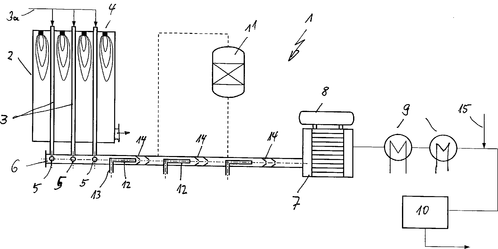
Weitere Merkmale, Einzelheiten und Vorteile der Erfindung ergeben sich aufgrund der nachfolgenden Beschreibung sowie anhand der Zeichnung. Diese zeigt inFurther Features, details and advantages of the invention will become apparent the following description and with reference to the drawing. These shows in
Die
wesentlichen Anlagenteile der in
Gestrichelt
dargestellt ist die Möglichkeit
eines ggf. externen (adiabaten) Katalysatorbettes
In
Lediglich
ausschnittsweise ist in den
Die
den Brennerkopf
Den
Porenbrennern ist gemein, daß in
der Brennerwand
In
Die
Strömungsrichtung
des Rohsynthesegases ist durch kleine Pfeile
In
In
In
Schließlich zeigt
Natürlich sind die beschriebenen Ausführungsbeispiele der Erfindung noch in vielfacher Hinsicht abzuändern, ohne den Grundgedanken zu verlassen. Dies gilt insbesondere für alle Gestaltungen des Porenbrenners und seine spezielle Positionierung in dem Strömungsweg des zu erhitzenden Gases.Of course they are the described embodiments to modify the invention in many ways, without the basic idea to leave. This applies in particular to all designs of the pore burner and its special positioning in the flow path of the to be heated Gas.
Claims (12)
Priority Applications (7)
| Application Number | Priority Date | Filing Date | Title |
|---|---|---|---|
| DE102005021500A DE102005021500A1 (en) | 2005-05-10 | 2005-05-10 | Process for heating a steam / natural gas mixture in the region of a gas collecting pipe after a primary reformer |
| EP06706982A EP1879832A1 (en) | 2005-05-10 | 2006-02-16 | Method for heating and partial oxidation of a steam/natural gas mixture after a primary reformer |
| RU2007145485/15A RU2394766C2 (en) | 2005-05-10 | 2006-02-16 | Method and installation for heating and partial oxidation of mixture of vapour and natural gas after primary reforming |
| US11/920,192 US7837974B2 (en) | 2005-05-10 | 2006-02-16 | Method for heating and partial oxidation of a steam/natural gas mixture after a primary reformer |
| PCT/EP2006/001380 WO2006119812A1 (en) | 2005-05-10 | 2006-02-16 | Method for heating and partial oxidation of a steam/natural gas mixture after a primary reformer |
| CNA2006800158216A CN101184688A (en) | 2005-05-10 | 2006-02-16 | Heating and partial oxidation of steam/natural gas mixture after primary reformer |
| JP2008510422A JP2008540310A (en) | 2005-05-10 | 2006-02-16 | Process for heating and partial oxidation of a steam / natural gas mixture after a first reformer |
Applications Claiming Priority (1)
| Application Number | Priority Date | Filing Date | Title |
|---|---|---|---|
| DE102005021500A DE102005021500A1 (en) | 2005-05-10 | 2005-05-10 | Process for heating a steam / natural gas mixture in the region of a gas collecting pipe after a primary reformer |
Publications (1)
| Publication Number | Publication Date |
|---|---|
| DE102005021500A1 true DE102005021500A1 (en) | 2006-11-16 |
Family
ID=36579537
Family Applications (1)
| Application Number | Title | Priority Date | Filing Date |
|---|---|---|---|
| DE102005021500A Withdrawn DE102005021500A1 (en) | 2005-05-10 | 2005-05-10 | Process for heating a steam / natural gas mixture in the region of a gas collecting pipe after a primary reformer |
Country Status (7)
| Country | Link |
|---|---|
| US (1) | US7837974B2 (en) |
| EP (1) | EP1879832A1 (en) |
| JP (1) | JP2008540310A (en) |
| CN (1) | CN101184688A (en) |
| DE (1) | DE102005021500A1 (en) |
| RU (1) | RU2394766C2 (en) |
| WO (1) | WO2006119812A1 (en) |
Cited By (5)
| Publication number | Priority date | Publication date | Assignee | Title |
|---|---|---|---|---|
| DE102011120938A1 (en) * | 2011-12-14 | 2013-06-20 | Thyssenkrupp Uhde Gmbh | Transportable reformer |
| WO2014095490A1 (en) * | 2012-12-18 | 2014-06-26 | Thyssenkrupp Uhde Gmbh | Reformer |
| WO2016066297A1 (en) * | 2014-10-31 | 2016-05-06 | Thyssenkrupp Industrial Solutions Ag | Reformer comprising porous or surface burners |
| EP3798180A1 (en) * | 2019-09-26 | 2021-03-31 | L'air Liquide, Société Anonyme Pour L'Étude Et L'exploitation Des Procédés Georges Claude | Reformer tube with improved heat transfer |
| DE102021109809A1 (en) | 2021-04-19 | 2022-10-20 | Dürr Systems Ag | THERMAL RAW GAS TREATMENT DEVICE |
Families Citing this family (18)
| Publication number | Priority date | Publication date | Assignee | Title |
|---|---|---|---|---|
| US8273139B2 (en) * | 2003-03-16 | 2012-09-25 | Kellogg Brown & Root Llc | Catalytic partial oxidation reforming |
| US8969644B2 (en) | 2007-02-06 | 2015-03-03 | Basf Se | Method for providing an oxygen-containing gas stream for the endothermic reaction of an initial stream comprising one or more hydrocarbons |
| FR2914396A1 (en) * | 2007-03-30 | 2008-10-03 | Inst Francais Du Petrole | NEW VAPOREFORMING OVEN USING POROUS BURNERS |
| DE102007019830B3 (en) | 2007-04-25 | 2008-07-31 | Uhde Gmbh | Reactor for catalytic primary reformation of hydrocarbons with water vapor under increased pressure, has device for top firring of reformation process furnace, and supply mechanism, which has main inlet channel and secondary inlet channel |
| DE102008012735B4 (en) | 2008-03-05 | 2013-05-08 | Thyssenkrupp Uhde Gmbh | Method and device for separating foreign gases from a reducing useful gas by steam-driven pressure swing adsorption |
| DE102010024539B4 (en) | 2010-06-21 | 2018-10-18 | Thyssenkrupp Industrial Solutions Ag | Primary reformer with variable flue gas flow |
| DE102009030480B3 (en) * | 2009-06-24 | 2010-08-05 | Uhde Gmbh | Reactor for catalytic primary reformation of hydrocarbons with steam, comprises reformer tube system used as reaction chamber, and burning chamber, where the reformer tube system has vertical tubes, feeding devices and discharging devices |
| MX2011013913A (en) | 2009-06-24 | 2012-02-23 | Thyssenkrupp Uhde Gmbh | Primary reformer having variable smoke gas flow. |
| US9500362B2 (en) * | 2010-01-21 | 2016-11-22 | Powerdyne, Inc. | Generating steam from carbonaceous material |
| KR20150053781A (en) | 2012-09-05 | 2015-05-18 | 파워다인, 인코포레이티드 | Fuel generation using high-voltage electric fields methods |
| EP2904221A4 (en) | 2012-09-05 | 2016-05-18 | Powerdyne Inc | Methods for power generation from h2o, co2, o2 and a carbon feed stock |
| EP2892643A4 (en) | 2012-09-05 | 2016-05-11 | Powerdyne Inc | Methods for generating hydrogen gas using plasma sources |
| WO2014039719A1 (en) | 2012-09-05 | 2014-03-13 | Powerdyne, Inc. | Fuel generation using high-voltage electric fields methods |
| KR20150053943A (en) | 2012-09-05 | 2015-05-19 | 파워다인, 인코포레이티드 | Fuel generation using high-voltage electric fields methods |
| EP2900353A4 (en) | 2012-09-05 | 2016-05-18 | Powerdyne Inc | Method for sequestering heavy metal particulates using h2o, co2, o2, and a source of particulates |
| KR101581263B1 (en) | 2012-09-05 | 2015-12-31 | 파워다인, 인코포레이티드 | System for generating fuel materials using fischer-tropsch catalysts and plasma sources |
| US20140072481A1 (en) * | 2012-09-13 | 2014-03-13 | John Scahill | Catalytic static mixing reactor |
| EP3647658B1 (en) * | 2018-11-01 | 2021-04-14 | L'air Liquide, Société Anonyme Pour L'Étude Et L'exploitation Des Procédés Georges Claude | Furnace for endothermic process and process for operating a furnace with improved burner arrangement |
Citations (6)
| Publication number | Priority date | Publication date | Assignee | Title |
|---|---|---|---|---|
| DE1920001A1 (en) * | 1969-04-19 | 1970-12-17 | Metallgesellschaft Ag | Process for the production of a synthesis gas for the production of ammonia |
| EP0200825A1 (en) * | 1985-05-08 | 1986-11-12 | Exxon Research And Engineering Company | Hydrocarbon steam reforming using series steam super heaters |
| EP0876993A1 (en) * | 1997-05-05 | 1998-11-11 | Haldor Topsoe A/S | Process and process unit for the preparation of ammonia synthesis gas |
| DE10230149A1 (en) * | 2002-07-04 | 2004-02-12 | Sgl Acotec Gmbh | Method and device for producing hydrogen |
| DE10239111A1 (en) * | 2002-08-27 | 2004-03-18 | Daimlerchrysler Ag | System for producing a hydrogen-containing gas from educts for operating fuel cells in vehicles comprises a reformer, a high temperature shift stage, a low temperature shift stage and a gas purification unit |
| US20050053816A1 (en) * | 2002-11-15 | 2005-03-10 | Anuj Bhargava | Burner for combusting the anode exhaust gas stream in a PEM fuel cell power plant |
Family Cites Families (11)
| Publication number | Priority date | Publication date | Assignee | Title |
|---|---|---|---|---|
| DE3513282C1 (en) | 1985-04-13 | 1986-06-12 | Programmelectronic Engineering AG, Dornach | Servomotor |
| DE4322109C2 (en) * | 1993-07-02 | 2001-02-22 | Franz Durst | Burner for a gas / air mixture |
| DE19625093A1 (en) * | 1996-06-24 | 1998-01-02 | Bayer Ag | Process for the production of carbon monoxide and hydrogen |
| DE19839782A1 (en) | 1998-09-01 | 2000-03-02 | Basf Ag | Metallic reactor tube, useful for the production of (meth)acrolein and/or (meth)acrylic acid by catalytic gas-phase oxidation of alkane or alkene etc. |
| DK173496B1 (en) * | 1998-07-16 | 2001-01-02 | Topsoe Haldor As | Process for producing synthesis gas by steam vapor reforming using a catalyzed metal surface |
| US7048772B1 (en) * | 1999-02-10 | 2006-05-23 | Casale Chemicals S.A. | Secondary reforming process and burner |
| DE19921420A1 (en) * | 1999-05-08 | 2000-11-16 | Krupp Uhde Gmbh | Primary reformer used in recovery of methanol, ammonia or hydrogen has heating tubes connected to tubular reformer with inner burner or tubular pore burner |
| EP1116689A1 (en) * | 2000-01-11 | 2001-07-18 | Haldor Topsoe A/S | Process and reactor for the preparation of hydrogen and carbon monoxide rich gas |
| EP1188713A3 (en) * | 2000-09-18 | 2003-06-25 | Haldor Topsoe A/S | Production of hydrogen and carbon monoxide containing synthesis gas by partial oxidation |
| ITMI20011553A1 (en) | 2001-07-20 | 2003-01-20 | Snam Progetti | PROCESS FOR THE SUMMARY OF AMMONIA |
| US20080028680A1 (en) * | 2003-04-15 | 2008-02-07 | Wouter Detlof Berggren | Process to Prepare Synthesis Gas |
-
2005
- 2005-05-10 DE DE102005021500A patent/DE102005021500A1/en not_active Withdrawn
-
2006
- 2006-02-16 US US11/920,192 patent/US7837974B2/en not_active Expired - Fee Related
- 2006-02-16 EP EP06706982A patent/EP1879832A1/en not_active Withdrawn
- 2006-02-16 WO PCT/EP2006/001380 patent/WO2006119812A1/en not_active Ceased
- 2006-02-16 CN CNA2006800158216A patent/CN101184688A/en active Pending
- 2006-02-16 RU RU2007145485/15A patent/RU2394766C2/en not_active IP Right Cessation
- 2006-02-16 JP JP2008510422A patent/JP2008540310A/en active Pending
Patent Citations (6)
| Publication number | Priority date | Publication date | Assignee | Title |
|---|---|---|---|---|
| DE1920001A1 (en) * | 1969-04-19 | 1970-12-17 | Metallgesellschaft Ag | Process for the production of a synthesis gas for the production of ammonia |
| EP0200825A1 (en) * | 1985-05-08 | 1986-11-12 | Exxon Research And Engineering Company | Hydrocarbon steam reforming using series steam super heaters |
| EP0876993A1 (en) * | 1997-05-05 | 1998-11-11 | Haldor Topsoe A/S | Process and process unit for the preparation of ammonia synthesis gas |
| DE10230149A1 (en) * | 2002-07-04 | 2004-02-12 | Sgl Acotec Gmbh | Method and device for producing hydrogen |
| DE10239111A1 (en) * | 2002-08-27 | 2004-03-18 | Daimlerchrysler Ag | System for producing a hydrogen-containing gas from educts for operating fuel cells in vehicles comprises a reformer, a high temperature shift stage, a low temperature shift stage and a gas purification unit |
| US20050053816A1 (en) * | 2002-11-15 | 2005-03-10 | Anuj Bhargava | Burner for combusting the anode exhaust gas stream in a PEM fuel cell power plant |
Cited By (6)
| Publication number | Priority date | Publication date | Assignee | Title |
|---|---|---|---|---|
| DE102011120938A1 (en) * | 2011-12-14 | 2013-06-20 | Thyssenkrupp Uhde Gmbh | Transportable reformer |
| US9821286B2 (en) | 2011-12-14 | 2017-11-21 | Thyssenkrupp Industrial Solutions Ag | Transportable reformer |
| WO2014095490A1 (en) * | 2012-12-18 | 2014-06-26 | Thyssenkrupp Uhde Gmbh | Reformer |
| WO2016066297A1 (en) * | 2014-10-31 | 2016-05-06 | Thyssenkrupp Industrial Solutions Ag | Reformer comprising porous or surface burners |
| EP3798180A1 (en) * | 2019-09-26 | 2021-03-31 | L'air Liquide, Société Anonyme Pour L'Étude Et L'exploitation Des Procédés Georges Claude | Reformer tube with improved heat transfer |
| DE102021109809A1 (en) | 2021-04-19 | 2022-10-20 | Dürr Systems Ag | THERMAL RAW GAS TREATMENT DEVICE |
Also Published As
| Publication number | Publication date |
|---|---|
| JP2008540310A (en) | 2008-11-20 |
| CN101184688A (en) | 2008-05-21 |
| US7837974B2 (en) | 2010-11-23 |
| US20080290322A1 (en) | 2008-11-27 |
| EP1879832A1 (en) | 2008-01-23 |
| RU2394766C2 (en) | 2010-07-20 |
| WO2006119812A1 (en) | 2006-11-16 |
| RU2007145485A (en) | 2009-06-20 |
Similar Documents
| Publication | Publication Date | Title |
|---|---|---|
| DE102005021500A1 (en) | Process for heating a steam / natural gas mixture in the region of a gas collecting pipe after a primary reformer | |
| EP0991587B1 (en) | Method and device for reforming hydrocarbons autothermally | |
| EP1532400B1 (en) | Method and device for combusting a fuel-oxidising agent mixture | |
| DE60112861T2 (en) | Apparatus and process for hydrocarbon reforming | |
| DE10262231B4 (en) | Process for the production of hydrogen | |
| DE112005000369T5 (en) | Integrated fuel processing plant for a decentralized hydrogen production | |
| DE112008001062T5 (en) | Compact reformer | |
| EP0832397B1 (en) | Catalytic gas turbine burner | |
| DE19934927A1 (en) | Process for cooling guide vanes and / or moving blades in the turbine stages of a gas turbine plant and gas turbine plant for carrying out the process | |
| DE102005038733A1 (en) | Fuel cell system and method of operating a reformer | |
| EP2167695B1 (en) | Method for the heat treatment of a metal band | |
| DE102005048385A1 (en) | Process for the evaporation and reforming of liquid fuels | |
| DE102008027882A1 (en) | Preparing carbon monoxide rich, methane-poor gas, comprises autothermal reforming of hydrocarbon-containing fuel with carbon dioxide, steam and an oxidant | |
| DE102006019409B4 (en) | Reformer reactor, its use and method of operation of the reformer | |
| EP3153464B1 (en) | Steam reformer for the production of synthesis gas | |
| DE102012010857A1 (en) | Removing device e.g. oven, for removing nitrogen oxide from flue gas, has burner arranged in radiation zone, and catalytic converter arranged within convection zone, where device conveys gas stream from radiation zone to convection zone | |
| DE102005026881A1 (en) | High-temperature reforming | |
| EP2912374A1 (en) | Method for generating water vapour | |
| DE102011015717A1 (en) | Heat recovery device for use in hydrogen system, has heat exchangers arranged in flow direction of flue gas, and bypass for controlling flow amount of combustion air and attached to one of heat exchangers, where bypass comprises valve | |
| EP4556434A1 (en) | Method and process arrangement for converting ammonia | |
| EP0860512B1 (en) | Method/apparatus for making a treating gas for the thermal treatment of a metallic product | |
| DE102023124322A1 (en) | Heating device and method for operating a heating device | |
| DE102024113652A1 (en) | Heat transfer device, use, installation and method | |
| DE3037601C2 (en) | METHOD AND DEVICE FOR REGULATING THE HIGH GAS HEATING OF COOKING OVENS | |
| DE102014018375A1 (en) | reactor |
Legal Events
| Date | Code | Title | Description |
|---|---|---|---|
| OP8 | Request for examination as to paragraph 44 patent law | ||
| R119 | Application deemed withdrawn, or ip right lapsed, due to non-payment of renewal fee |
Effective date: 20111201 |