DE102004020655B4 - Locking unit for a movable closing element - Google Patents
Locking unit for a movable closing element Download PDFInfo
- Publication number
- DE102004020655B4 DE102004020655B4 DE200410020655 DE102004020655A DE102004020655B4 DE 102004020655 B4 DE102004020655 B4 DE 102004020655B4 DE 200410020655 DE200410020655 DE 200410020655 DE 102004020655 A DE102004020655 A DE 102004020655A DE 102004020655 B4 DE102004020655 B4 DE 102004020655B4
- Authority
- DE
- Germany
- Prior art keywords
- rotors
- locked position
- distance
- axis
- locked
- Prior art date
- Legal status (The legal status is an assumption and is not a legal conclusion. Google has not performed a legal analysis and makes no representation as to the accuracy of the status listed.)
- Expired - Fee Related
Links
- 230000002093 peripheral effect Effects 0.000 claims abstract description 28
- 230000001960 triggered effect Effects 0.000 claims description 26
- 238000010276 construction Methods 0.000 description 10
- 210000000689 upper leg Anatomy 0.000 description 9
- 239000000463 material Substances 0.000 description 8
- 210000002414 leg Anatomy 0.000 description 7
- 239000007769 metal material Substances 0.000 description 7
- 230000004888 barrier function Effects 0.000 description 5
- 239000002131 composite material Substances 0.000 description 3
- 238000004519 manufacturing process Methods 0.000 description 3
- 239000002184 metal Substances 0.000 description 3
- 238000013459 approach Methods 0.000 description 2
- 239000011521 glass Substances 0.000 description 2
- 238000000034 method Methods 0.000 description 2
- 230000008569 process Effects 0.000 description 2
- 230000003068 static effect Effects 0.000 description 2
- 239000000126 substance Substances 0.000 description 2
- FGRBYDKOBBBPOI-UHFFFAOYSA-N 10,10-dioxo-2-[4-(N-phenylanilino)phenyl]thioxanthen-9-one Chemical compound O=C1c2ccccc2S(=O)(=O)c2ccc(cc12)-c1ccc(cc1)N(c1ccccc1)c1ccccc1 FGRBYDKOBBBPOI-UHFFFAOYSA-N 0.000 description 1
- 238000005452 bending Methods 0.000 description 1
- 230000008859 change Effects 0.000 description 1
- 238000005260 corrosion Methods 0.000 description 1
- 230000007797 corrosion Effects 0.000 description 1
- 230000001419 dependent effect Effects 0.000 description 1
- 230000000694 effects Effects 0.000 description 1
- 238000009434 installation Methods 0.000 description 1
- 230000003993 interaction Effects 0.000 description 1
- 230000007246 mechanism Effects 0.000 description 1
- 238000003825 pressing Methods 0.000 description 1
- 238000004080 punching Methods 0.000 description 1
- 230000003252 repetitive effect Effects 0.000 description 1
- 230000000717 retained effect Effects 0.000 description 1
Classifications
-
- E—FIXED CONSTRUCTIONS
- E05—LOCKS; KEYS; WINDOW OR DOOR FITTINGS; SAFES
- E05B—LOCKS; ACCESSORIES THEREFOR; HANDCUFFS
- E05B85/00—Details of vehicle locks not provided for in groups E05B77/00 - E05B83/00
- E05B85/20—Bolts or detents
- E05B85/24—Bolts rotating about an axis
- E05B85/247—Bolts rotating about an axis about a vertical axis
-
- E—FIXED CONSTRUCTIONS
- E05—LOCKS; KEYS; WINDOW OR DOOR FITTINGS; SAFES
- E05B—LOCKS; ACCESSORIES THEREFOR; HANDCUFFS
- E05B63/00—Locks or fastenings with special structural characteristics
- E05B63/14—Arrangement of several locks or locks with several bolts, e.g. arranged one behind the other
-
- E—FIXED CONSTRUCTIONS
- E05—LOCKS; KEYS; WINDOW OR DOOR FITTINGS; SAFES
- E05C—BOLTS OR FASTENING DEVICES FOR WINGS, SPECIALLY FOR DOORS OR WINDOWS
- E05C3/00—Fastening devices with bolts moving pivotally or rotatively
- E05C3/12—Fastening devices with bolts moving pivotally or rotatively with latching action
- E05C3/16—Fastening devices with bolts moving pivotally or rotatively with latching action with operating handle or equivalent member moving otherwise than rigidly with the latch
- E05C3/22—Fastening devices with bolts moving pivotally or rotatively with latching action with operating handle or equivalent member moving otherwise than rigidly with the latch the bolt being spring controlled
- E05C3/30—Fastening devices with bolts moving pivotally or rotatively with latching action with operating handle or equivalent member moving otherwise than rigidly with the latch the bolt being spring controlled in the form of a hook
- E05C3/34—Fastening devices with bolts moving pivotally or rotatively with latching action with operating handle or equivalent member moving otherwise than rigidly with the latch the bolt being spring controlled in the form of a hook with simultaneously operating double bolts
-
- E—FIXED CONSTRUCTIONS
- E05—LOCKS; KEYS; WINDOW OR DOOR FITTINGS; SAFES
- E05B—LOCKS; ACCESSORIES THEREFOR; HANDCUFFS
- E05B85/00—Details of vehicle locks not provided for in groups E05B77/00 - E05B83/00
- E05B85/20—Bolts or detents
- E05B85/24—Bolts rotating about an axis
- E05B85/245—Bolts rotating about an axis with a pair of bifurcated bolts
-
- Y—GENERAL TAGGING OF NEW TECHNOLOGICAL DEVELOPMENTS; GENERAL TAGGING OF CROSS-SECTIONAL TECHNOLOGIES SPANNING OVER SEVERAL SECTIONS OF THE IPC; TECHNICAL SUBJECTS COVERED BY FORMER USPC CROSS-REFERENCE ART COLLECTIONS [XRACs] AND DIGESTS
- Y10—TECHNICAL SUBJECTS COVERED BY FORMER USPC
- Y10S—TECHNICAL SUBJECTS COVERED BY FORMER USPC CROSS-REFERENCE ART COLLECTIONS [XRACs] AND DIGESTS
- Y10S292/00—Closure fasteners
- Y10S292/23—Vehicle door latches
-
- Y—GENERAL TAGGING OF NEW TECHNOLOGICAL DEVELOPMENTS; GENERAL TAGGING OF CROSS-SECTIONAL TECHNOLOGIES SPANNING OVER SEVERAL SECTIONS OF THE IPC; TECHNICAL SUBJECTS COVERED BY FORMER USPC CROSS-REFERENCE ART COLLECTIONS [XRACs] AND DIGESTS
- Y10—TECHNICAL SUBJECTS COVERED BY FORMER USPC
- Y10T—TECHNICAL SUBJECTS COVERED BY FORMER US CLASSIFICATION
- Y10T292/00—Closure fasteners
- Y10T292/08—Bolts
- Y10T292/0801—Multiple
- Y10T292/081—Swinging and hooked end
-
- Y—GENERAL TAGGING OF NEW TECHNOLOGICAL DEVELOPMENTS; GENERAL TAGGING OF CROSS-SECTIONAL TECHNOLOGIES SPANNING OVER SEVERAL SECTIONS OF THE IPC; TECHNICAL SUBJECTS COVERED BY FORMER USPC CROSS-REFERENCE ART COLLECTIONS [XRACs] AND DIGESTS
- Y10—TECHNICAL SUBJECTS COVERED BY FORMER USPC
- Y10T—TECHNICAL SUBJECTS COVERED BY FORMER US CLASSIFICATION
- Y10T292/00—Closure fasteners
- Y10T292/08—Bolts
- Y10T292/1043—Swinging
- Y10T292/1044—Multiple head
- Y10T292/1045—Operating means
- Y10T292/1047—Closure
-
- Y—GENERAL TAGGING OF NEW TECHNOLOGICAL DEVELOPMENTS; GENERAL TAGGING OF CROSS-SECTIONAL TECHNOLOGIES SPANNING OVER SEVERAL SECTIONS OF THE IPC; TECHNICAL SUBJECTS COVERED BY FORMER USPC CROSS-REFERENCE ART COLLECTIONS [XRACs] AND DIGESTS
- Y10—TECHNICAL SUBJECTS COVERED BY FORMER USPC
- Y10T—TECHNICAL SUBJECTS COVERED BY FORMER US CLASSIFICATION
- Y10T292/00—Closure fasteners
- Y10T292/08—Bolts
- Y10T292/1043—Swinging
- Y10T292/1075—Operating means
- Y10T292/1082—Motor
Landscapes
- Engineering & Computer Science (AREA)
- Mechanical Engineering (AREA)
- Structural Engineering (AREA)
- Lock And Its Accessories (AREA)
Abstract
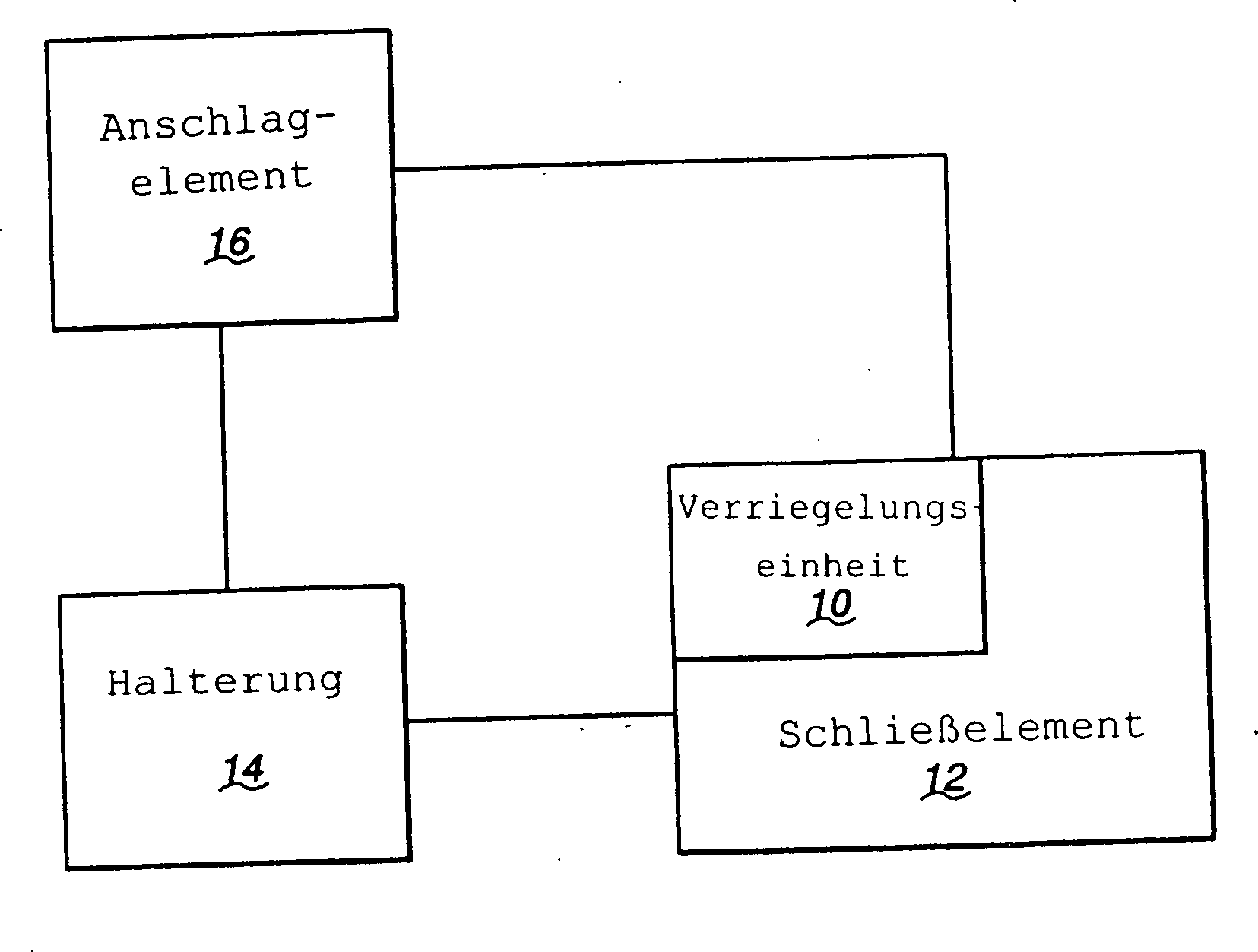
Verriegelungseinheit für ein bewegliches Schließelement (12), umfassend:
ein Gehäuse (18) mit einer peripheren Kante (200), die teilweise durch einen im wesentlichen geraden Kantenteil (208) definiert ist, der sich entlang einer Referenzlinie (RL) erstreckt,
einen ersten und einen zweiten Rotor (46, 46'), die relativ zum Gehäuse (18) wählbar zwischen einer ersten und einer zweiten verriegelten Position und einer ausgelösten Position beweglich sind, wobei die zweite verriegelte Position zwischen der ersten verriegelten Position und der ausgelösten Position befindlich ist, und
eine Betätigungseinheit (78), die einen verriegelten Zustand und einen unverriegelten Zustand aufweist und die in ihrem verriegelten Zustand die beiden Rotoren (46, 46') lösbar in der ersten und in der zweiten verriegelten Position hält,
worin die beiden Rotoren (46, 46') in der ersten und in der zweiten verriegelten Position eine Aufnahme (72) mit einem effektiven Durchmesser (D) und einer Achse (196) definieren, die zur ersten Linie (L) unter...A locking unit for a movable closure member (12), comprising:
a housing (18) having a peripheral edge (200) defined in part by a substantially straight edge portion (208) extending along a reference line (RL);
a first and a second rotor (46, 46 ') selectively movable relative to the housing (18) between a first and a second locked position and a deployed position, the second locked position between the first locked position and the released position is located, and
an actuator unit (78) having a locked state and an unlatched state and which in its locked state releasably holds the two rotors (46, 46 ') releasably in the first and second latched positions,
wherein the two rotors (46, 46 ') define, in the first and second latched positions, a receptacle (72) having an effective diameter (D) and an axis (196) facing the first line (L) below the first rotat ...
Description
Die Erfindung bezieht sich auf eine Verriegelungseinheit, die verwendet werden kann, um ein bewegliches Schließelement in einer gewünschten Position relativ zu einer Halterung lösbar zu halten.The The invention relates to a locking unit that uses can be a moving closure element in a desired Position releasably relative to a holder.
Bewegliche Schließelemente werden in vielen Industriebereichen sowohl in statischen Umgebungen wie auch in beweglichen Anlagen verwendet. Diese Schließelemente werden üblicherweise zwischen verschiedenen Positionen gedreht oder verschoben, normalerweise geöffneten und geschlossenen Positionen, um wahlweise den Zugang zu einem Raum, vor dem sich das Schließelement befindet, zu blockieren oder zu ermöglichen.portable closing elements are used in many industrial sectors both in static environments as used in mobile systems. These closing elements become common rotated or moved between different positions, usually open and closed positions to selectively access a room, in front of the closing element is to block or allow.
Eine
Verriegelungseinheit, die mit der oben erwähnten Art von Schließelementen
verwendet wird, ist in
Ein Problem dieser vorbekannten Verriegelungseinheit ist der Tatsache zuzuordnen, dass das Schließelement fast geschlossen sein muss, damit die Rotoren die zweiten verriegelten Positionen erreichen. Der gegenwärtige Aufbau der Glastüren landwirtschaftlicher Traktoren benötigt eine erhebliche, in die Tür eingebaute Biegung, um die Eigenbiegung der Tür zu kompensieren. Zusätzlich benötigen Voll-Glas-Türen mehr Wucht, um bis zu dem Punkt geschlossen zu werden, an dem die Rotoren ihre zweite verriegelte Position erreichen und einige erreichen nie den vollständig geschlossenen Zustand an dem Punkt, an dem die Rotoren ihre erste verriegelten Positionen erreichen. Es wurde beobachtet, dass Türen versehentlich halb offen gelassen wurden. Wird die Anlage bei hohen Geschwindigkeiten befördert, kann die Tür auffliegen und möglicherweise zerschellen.One Problem of this prior art locking unit is the fact assign that the closing element must be almost closed so that the rotors locked the second Reach positions. The current one Construction of the glass doors Agricultural tractors require a substantial, in the Door built-in Bend to compensate for the self-bending of the door. In addition, full-glass doors need more Balanced to be closed to the point where the rotors reach their second locked position and reach some never complete closed state at the point where the rotors their first reach locked positions. It was observed that doors accidentally were left half open. Will the plant be at high speeds promoted can the door fly up and possibly shatter.
Ein weiteres Problem der Verriegelungseinheiten nach dem Stand der Technik ist, dass bei konventionellen Konstruktionen der Verriegelungseinheiten die zweiten verriegelten Positionen der Rotoren von den ersten verriegelten Positionen durch Betrachtung des Schließelementes nahezu nicht unterscheidbar sind. Als Ergebnis kann ein Benutzer fälschlicherweise annehmen, dass das unverriegelte Schließelement, das nur leicht angelehnt ist, so positioniert ist, dass sich die Rotoren in ihren zweiten verriegelten Positionen befinden. Dies kann zu einer Situation führen, in der das Schließelement unabsichtlich geöffnet oder auf andere Art eine unerwünschte Umpositionierung ermöglicht wird. Ein weiteres mögliches Problem liegt im Herstellungs- und Montagevorgang, der zu zusätzlich benötigter Zeit bei der Installation der Verriegelung und der Tür und zu Nacharbeit und Garantiekosten führen kann, um diesen Zustand im Gebrauch zu beheben.One Another problem of the locking units according to the prior art is that in conventional constructions the locking units the second locked positions of the rotors of the first locked Positions by viewing the closing element almost indistinguishable are. As a result, a user may erroneously assume that the unlocked closing element, which is only slightly ajar, is positioned so that the Rotors are in their second locked positions. This can lead to a situation in the the closing element unintentionally opened or otherwise undesirable repositioning allows becomes. Another possible Problem lies in the manufacturing and assembly process, the additional time required during the installation of the lock and the door and for rework and warranty costs to lead can to fix this condition in use.
Der Erfindung liegt von daher die Aufgabe zugrunde, die zweite verriegelte Position, d. h. die Sicherheitsraststellung, von der ersten verriegelten Position, d. h. der vollständigen Schließposition, durch Betrachtung des Schließelementes unterscheidbar zu machen, so dass der Benutzer sich darauf verlassen kann, dass das Schließelement bereits in der zweiten verriegelten Position, d. h. der Sicherheitsraststellung, ausreichend verriegelt ist.Of the Invention is therefore based on the object, the second locked Position, d. H. the safety catch position, locked from the first Position, d. H. the complete Closed position, by looking at the closing element make it distinguishable so that the user can rely on it that can be the closing element already in the second locked position, d. H. the safety catch position, is sufficiently locked.
Zur Lösung der Aufgabe sieht die Erfindung gemäß dem Patentanspruch 1 eine Verriegelungseinheit für ein bewegliches Schließelement vor, die folgende Merkmale umfasst: ein Gehäuse mit einer peripheren Kante, die teilweise durch einen im wesentlichen geraden Kantenteil definiert ist, der sich entlang einer Referenzlinie erstreckt, einen ersten und einen zweiten Rotor, die relativ zum Gehäuse wählbar zwischen einer ersten und einer zweiten verriegelten Position und einer ausgelösten Position beweglich sind, wobei die zweite verriegelte Position zwischen der ersten verriegelten Position und der ausgelösten Position befindlich ist, und eine Betätigungseinheit, die einen verriegelten Zustand und einen unverriegelten Zustand aufweist und die in ihrem verriegelten Zustand die beiden Rotoren lösbar in der ersten und in der zweiten verriegelten Positionen hält, worin die beiden Rotoren in der ersten und in der zweiten verriegelten Position eine Aufnahme mit einem effektiven Durchmesser und einer Achse definieren, die zur Referenzlinie unter einem Winkel geneigt ist, und sich in der zweiten verriegelten Position vollständig um die Aufnahme erstrecken, worin, wenn die beiden Rotoren in der ersten verriegelten Position sind, die Achse der Aufnahme von der Referenzlinie um eine erste Distanz beabstandet ist, worin die Achse der Aufnahme in einer ersten Lage, wenn die beiden Rotoren in der ersten verriegelten Position sind, und in einer zweiten Lage angeordnet ist, wenn die beiden Rotoren in der zweiten verriegelten Position sind, worin die ersten und zweiten Lagen voneinander um eine zweite Distanz beabstandet sind, und worin, wenn die beiden Rotoren in der ersten verriegelten Positionen sind, der effektive Durchmesser der Aufnahme von der ersten Distanz und von der zweiten Distanz um nicht mehr als +40% abweicht.to solution The object of the invention according to claim 1 provides a Locking unit for a movable closing element comprising: a housing having a peripheral edge, partially defined by a substantially straight edge portion which extends along a reference line, a first and a second rotor, which is selectable relative to the housing between a first and a second locked position and a released position are movable, wherein the second locked position between the first locked position and the triggered position, and an operating unit, the one locked state and an unlocked state and in their locked state, the two rotors solvable in the first and second locked positions, wherein the two rotors locked in the first and in the second Position a recording with an effective diameter and a Define axis that is inclined to the reference line at an angle is complete, and in the second locked position completely extend the receptacle, wherein, when the two rotors in the first locked position, the axis of the recording of the reference line spaced apart by a first distance, wherein the axis of the receptacle in a first position when the two rotors locked in the first Position are, and arranged in a second position when the both rotors are in the second locked position, wherein the first and second layers apart by a second distance are spaced, and wherein when the two rotors in the first Locked positions are the effective diameter of the receptacle from the first distance and from the second distance no more than + 40%.
Damit wird erreicht, dass die zweite verriegelte Position von der ersten verriegelten Position durch Betrachtung des Schließelementes unterscheidbar ist, so dass der Benutzer sich darauf verlassen kann, dass das Schließelement bereits in der zweiten verriegelten Position, d. h. der Sicherheitsraststellung, ausreichend verriegelt ist.In order to is achieved that the second locked position of the first Locked position by viewing the closing element is distinguishable so that the user can rely on it that the closing element already in the second locked position, d. H. the safety catch position, is sufficiently locked.
Weitere vorteilhafte Ausführungsformen der Erfindung ergeben sich aus den Unteransprüchen. So ist, wenn die beiden Rotoren in der ersten verriegelten Position sind, der effektive Durchmesser der Aufnahme in etwa gleich der zweiten Distanz. Das Verhältnis der ersten Distanz zum effektiven Durchmesser der Aufnahme ist, wenn die beiden Rotoren in der ersten verriegelten Position sind, kleiner als eins. Der effektive Durchmesser der Aufnahme, wenn die beiden Rotoren in der ersten verriegelten Position sind, und die zweite Distanz sind in etwa gleich groß.Further advantageous embodiments The invention will become apparent from the dependent claims. Such is when the two Rotors in the first locked position are the most effective Diameter of the recording approximately equal to the second distance. The ratio of first distance to the effective diameter of the recording is, if the two rotors are in the first locked position, smaller as one. The effective diameter of the recording when the two Rotors are in the first locked position, and the second Distance are about the same size.
In einer weiteren Ausführungsform sind der erste Rotor um eine erste Drehachse zwischen seiner ersten verriegelten und seiner ausgelösten Position, und der zweite Rotor um eine zweite Achse, die im wesentlichen parallel zur ersten Achse ist, zwischen seiner ersten verriegelten und seiner ausgelösten Position beweglich und, wenn die beiden Rotoren in der zweiten verriegelten Position sind, erstreckt sich die Achse der Aufnahme im wesentlichen parallel zu den ersten und zweiten Achsen und ist von einer Linie, die sich zwischen den ersten und zweiten Achsen erstreckt, um eine dritte Distanz beabstandet, die wesentlich größer als 0,35 Inch ist. Die dritte Distanz ist in der Größenordnung von 0,75 Inch. Die ersten und zweiten Achsen sind voneinander um eine Distanz in der Größenordnung von 2,5 Inch beabstandet. Die Achse der Aufnahme befindet sich, wenn die beiden Rotoren in der ersten verriegelten Position sind, innerhalb der peripheren Kante des Gehäuses. Die Achse der Aufnahme befindet sich, wenn die beiden Rotoren in der zweiten verriegelten Position sind, außerhalb der peripheren Kante des Gehäuses.In a further embodiment are the first rotor about a first axis of rotation between its first locked and its triggered Position, and the second rotor about a second axis, which is substantially is parallel to the first axis, between its first locked and his triggered Position movable and when the two rotors locked in the second Position, the axis of the receptacle extends substantially parallel to the first and second axes and is from a line that is extends between the first and second axes to a third Distance spaced much larger than 0.35 inches. The third Distance is on the order of magnitude of 0.75 inches. The first and second axes are one to another Distance in the order of magnitude spaced 2.5 inches apart. The axis of the recording is when the two rotors are in the first locked position, within the peripheral edge of the housing. The axis of the recording is when the two rotors in the second locked position are outside the peripheral edge of the housing.
Zur Lösung der Aufgabe sieht die Erfindung gemäß dem ersten nebengeordneten Patentanspruch 10 eine Verriegelungseinheit für ein bewegliches Schließelement vor, die folgende Merkmale umfasst: ein Gehäuse mit einer peripheren Kante, die teilweise durch einen im wesentlichen geraden Kantenteil definiert ist, der sich entlang einer Referenzlinie erstreckt, einen ersten und einen zweiten Rotor, die relativ zum Gehäuse wählbar zwischen einer ersten und einer zweiten verriegelten Position und einer ausgelösten Position beweglich sind, wobei die zweite verriegelte Position zwischen der ersten verriegelten Position und der ausgelösten Position befindlich ist, eine Betätigungseinheit, die einen verriegelten Zustand und einen unverriegelten Zustand aufweist und die in ihrem verriegelten Zustand die beiden Rotoren lösbar in der ersten und in der zweiten verriegelten Position hält, worin die beiden Rotoren in der ersten und in der zweiten verriegelten Position eine Aufnahme mit einem effektiven Durchmesser und einer Achse definieren, die zur Referenzlinie unter einem Winkel geneigt ist, und sich in der zweiten verriegelten Position vollständig um die Aufnahme erstrecken, und ein Anschlagelement, das einen Durchmesser zum Halten in der Aufnahme, wenn die beiden Rotoren in der ersten oder zweiten verriegelten Stellung sind, und eine Achse, die zur Referenzlinie unter einem Winkel geneigt ist, worin, wenn die beiden Rotoren in der ersten verriegelten Position sind, die Achse des Anschlagelementes in der Aufnahme von der Referenzlinie um eine erste Distanz beabstandet ist, worin die Achse des Anschlagelementes in der Aufnahme in einer ersten Lage, wenn die beiden Rotoren in der ersten verriegelten Position sind, und in einer zweiten Lage angeordnet ist, wenn die beiden Rotoren in der zweiten verriegelten Position sind, und worin die ersten und zweiten Lagen voneinander um eine zweite Distanz beabstandet sind, und worin der Durchmesser des Anschlagelementes von der ersten Distanz und von der zweiten Distanz um nicht mehr als +40% abweicht.to solution the task is the invention according to the first sibling Claim 10 a locking unit for a movable closing element comprising: a housing having a peripheral edge, partially defined by a substantially straight edge portion is, which extends along a reference line, a first and a second rotor selectable relative to the housing between a first one and a second locked position and a released position are movable, wherein the second locked position between the first locked position and the triggered position, an operating unit, the one locked state and an unlocked state and in their locked state, the two rotors solvable in the first and second locked positions, wherein the two rotors locked in the first and in the second Position a recording with an effective diameter and a Define axis that is inclined to the reference line at an angle is complete, and in the second locked position completely extend the receptacle, and a stop member having a diameter to hold in the receptacle when the two rotors in the first or second locked position, and an axis to the Reference line is inclined at an angle, wherein if the two Rotors in the first locked position are the axis of the Stop element in the recording of the reference line to a spaced first distance, wherein the axis of the stop element in the receptacle in a first position when the two rotors in the first locked position, and in a second position is arranged when the two rotors locked in the second Position, and wherein the first and second layers of each other spaced apart by a second distance, and wherein the diameter the stop element from the first distance and from the second Distance does not deviate by more than + 40%.
In weiteren Ausführungsformen ist der Durchmesser des Anschlagelementes etwa gleich der zweiten Distanz. Ferner ist das Verhältnis der ersten Distanz zum Durchmesser des Anschlagelementes kleiner als eins. Ausserdem sind der Durchmesser des Anschlagelementes, die erste Distanz und die zweite Distanz etwa gleich groß.In further embodiments the diameter of the stop element is approximately equal to the second Distance. Further, the ratio the first distance to the diameter of the stop element smaller as one. In addition, the diameter of the stop element, the first distance and the second distance about the same size.
In einer zugehörigen Ausführungsform sind der erste Rotor um eine erste Drehachse zwischen seiner ersten verriegelten Stellung und seiner ausgelösten Stellung und der zweite Rotor um eine zweite Achse, die im wesentlichen zur ersten Achse parallel ist, zwischen seinen ersten verriegelten und ausgelösten Positionen beweglich, wobei die Achse des Anschlagelementes sich im wesentlichen parallel zu den ersten und zweiten Achsen erstreckt und die Achse des Anschlagelementes von der sich zwischen den ersten und zweiten Achsen erstreckenden Linie um eine dritte Distanz beabstandet ist, die im wesentlichen größer als 0,35 Inch ist, wenn die beiden Rotoren in der zweiten verriegelten Position sind.In an associated one embodiment are the first rotor about a first axis of rotation between its first locked position and its released position and the second Rotor about a second axis, which is substantially to the first axis parallel, between his first locked and tripped positions movable, wherein the axis of the stop element is substantially extending parallel to the first and second axes and the axis the stop element of the between the first and second Axis extending line is spaced a third distance, which are essentially larger than 0.35 inches is when the two rotors locked in the second Position are.
Hierbei ist die dritte Distanz in der Größenordnung von 0,75 Inch. Die beiden Achsen sind zueinander in der Größenordnung von 2,5 Inch beabstandet. Die Achse des Anschlagelements befindet sich, wenn die beiden Rotoren in der ersten verriegelten Position sind, innerhalb der peripheren Kante des Gehäuses. Ferner befindet sich die Achse des Anschlagelements, wenn die beiden Rotoren in der zweiten verriegelten Position sind, außerhalb der peripheren Kante des Gehäuses.in this connection is the third distance on the order of magnitude of 0.75 inches. The two axes are of the same order of magnitude spaced 2.5 inches apart. The axis of the stop element is located, when the two rotors are in the first locked position, inside the peripheral edge of the case. It is also located the axis of the stop element when the two rotors in the second locked position are outside the peripheral edge of the housing.
Zur Lösung der Aufgabe sieht die Erfindung ferner gemäß dem zweiten nebengeordneten Patentanspruch 19 eine Verriegelungseinheit für ein bewegliches Schließelement vor, die folgende Merkmale umfasst: ein Gehäuse mit einer peripheren Kante, die teilweise durch einen im wesentlichen geraden Kantenteil definiert ist, der sich entlang einer Referenzlinie erstreckt, einen ersten und einen zweiten Rotor, die relativ zum Gehäuse wählbar zwischen einer ersten und einer zweiten verriegelten Position und einer ausgelösten Position beweglich sind, wobei die zweite verriegelte Position zwischen der ersten verriegelten Position und der ausgelösten Position befindlich ist, und eine Betätigungseinheit, die einen verriegelten Zustand und einen unverriegelten Zustand aufweist und die in ihrem verriegelten Zustand die beiden Rotoren lösbar in der ersten und in der zweiten verriegelten Positionen hält, worin die beiden Rotoren in der ersten und in der zweiten verriegelten Position eine Aufnahme mit einem effektiven Durchmesser und einer Achse definieren, die zur Referenzlinie unter einem Winkel geneigt ist, und sich in der zweiten verriegelten Position vollständig um die Aufnahme erstrecken, worin, wenn die beiden Rotoren in der ersten verriegelten Position sind, die Achse der Aufnahme von der Referenzlinie um eine erste Distanz beabstandet ist, worin die Achse der Aufnahme in einer ersten Lage, wenn die beiden Rotoren in der ersten verriegelten Position sind, und in einer zweiten Lage angeordnet ist, wenn die beiden Rotoren in der zweiten verriegelten Position sind, worin die ersten und zweiten Lagen voneinander um eine zweite Distanz beabstandet sind, und worin, wenn die beiden Rotoren in der ersten verriegelten Position sind, der effektive Durchmesser der Aufnahme von der zweiten Distanz um nicht mehr als ±20% abweicht.to solution The object of the invention further provides according to the second sibling Claim 19, a locking unit for a movable closing element comprising: a housing having a peripheral edge which partially defined by a substantially straight edge portion is, which extends along a reference line, a first and a second rotor selectable relative to the housing between a first one and a second locked position and a released position are movable, wherein the second locked position between the first locked position and the triggered position, and an operating unit, the one locked state and an unlocked state and in their locked state, the two rotors solvable in the first and second locked positions, wherein the two rotors locked in the first and in the second Position a recording with an effective diameter and a Define axis that is inclined to the reference line at an angle is complete, and in the second locked position completely extend the receptacle, wherein, when the two rotors in the first locked position, the axis of the recording of the reference line spaced apart by a first distance, wherein the axis of the receptacle in a first position when the two rotors locked in the first Position are, and arranged in a second position when the both rotors are in the second locked position, wherein the first and second layers apart by a second distance are spaced, and wherein when the two rotors in the first Locked position, the effective diameter of the recording from the second distance by no more than ± 20%.
In einer zugehörigen Ausführungsform weicht der effektive Durchmesser der Aufnahme, wenn die beiden Rotoren in der ersten verriegelten Position sind, von der zweiten Distanz um nicht mehr als +15% ab. Das Verhältnis der ersten Distanz zum effektiven Durchmesser der Aufnahme ist, wenn die beiden Rotoren in ihren ersten verriegelten Position sind, kleiner als eins.In an associated one Embodiment gives way the effective diameter of the receptacle when the two rotors are in the first locked position, from the second distance by no more than + 15%. The ratio of the first distance to the effective one Diameter of the recording is when the two rotors in their first locked position are less than one.
Der effektive Durchmesser der Aufnahme, wenn die beiden Rotoren in der ersten verriegelten Position sind, und die zweite Distanz sind in etwa gleich groß. Ferner befindet sich die Achse des Anschlagelements, wenn die beiden Rotoren in der ersten verriegelten Position sind, innerhalb der peripheren Kante des Gehäuses. Schließlich befindet sich die Achse des Anschlagelements, wenn die beiden Rotoren in der zweiten verriegelten Position sind, außerhalb der peripheren Kante des Gehäuses.Of the effective diameter of the intake when the two rotors in the first locked position, and the second distance are in about the same size. Further, the axis of the stopper member is when the two Rotors in the first locked position are within the peripheral edge of the housing. After all is the axis of the stop element when the two rotors in the second locked position, outside the peripheral edge of the housing.
Zur Lösung der Aufgabe sieht die Erfindung schließlich gemäß dem dritten nebengeordneten Patentanspruch 25 eine Verriegelungsinheit für ein bewegliches Schließelement vor, die folgende Merkmale umfasst: ein Gehäuse mit einer peripheren Kante, die teilweise durch einen im wesentlichen geraden Kantenteil definiert ist, der sich entlang einer Referenzlinie erstreckt, einen ersten und einen zweiten Rotor, die relativ zum Gehäuse wählbar zwischen einer ersten und einer zweiten verriegelten Position und einer ausgelösten Position beweglich sind, wobei die zweite verriegelte Position zwischen der ersten verriegelten Position und der ausgelösten Position befindlich ist, eine Betätigungseinheit, die einen verriegelten Zustand und einen unverriegelten Zustand aufweist und die in ihrem verriegelten Zustand die beiden Rotoren lösbar in der ersten und in der zweiten verriegelten Position hält, worin die beiden Rotoren in der ersten und in der zweiten verriegelten Position eine Aufnahme mit einem effektiven Durchmesser und einer Achse definieren, die zur Referenzlinie unter einem Winkel geneigt ist, und sich in der zweiten verriegelten Position vollständig um die Aufnahme erstrecken, und ein Anschlagelement, das einen Durchmesser zum Halten in der Aufnahme aufweist, wenn die beiden Rotoren in der ersten oder zweiten verriegelten Stellung sind, und eine Achse aufweist, worin, wenn die beiden Rotoren in der ersten verriegelten Position sind, sich das Anschlagelement bis neben die Referenzlinie erstreckt, worin, wenn die beiden Rotoren in der ersten verriegelten Position sind, die Achse des Anschlagelementes in der Aufnahme von der Referenzlinie um eine erste Distanz beabstandet ist, worin die Achse des Anschlagelementes in der Aufnahme in einer ersten Lage, wenn die beiden Rotoren in der ersten verriegelten Position sind, und in einer zweiten Lage angeordnet ist, wenn die beiden Rotoren in der zweiten verriegelten Position sind, worin die ersten und zweiten Lagen voneinander um eine zweite Distanz beabstandet sind, und worin der Durchmesser des Anschlagelementes von der zweiten Distanz um nicht mehr als +20% abweicht.to solution the task finally sees the invention according to the third sibling Claim 25, a locking unit for a movable closing element comprising: a housing having a peripheral edge which partially defined by a substantially straight edge portion is, which extends along a reference line, a first and a second rotor selectable relative to the housing between a first one and a second locked position and a released position are movable, wherein the second locked position between the first locked position and the triggered position, an operating unit, the one locked state and an unlocked state and in their locked state, the two rotors solvable in the first and second locked positions, wherein the two rotors in the first and in the second locked position define a recording with an effective diameter and an axis, which is inclined at an angle to the reference line, and located in the second locked position extend completely around the receptacle, and a stopper member having a diameter for holding in the Has recording when the two rotors in the first or second locked position, and having an axis, wherein, when the two rotors are in the first locked position the stopper member extends adjacent to the reference line, wherein, when the two rotors are in the first locked position, the Axle of the stop element in the receptacle from the reference line spaced by a first distance, wherein the axis of the stop element in the receptacle in a first position when the two rotors in the first locked position, and in a second position is arranged when the two rotors locked in the second Position are, wherein the first and second layers of each other a second distance, and wherein the diameter the stop element of the second distance by not more than + 20% deviates.
Dabei ist der Durchmesser des Anschlagelementes in etwa gleich der zweiten Distanz. Das Verhältnis der ersten Distanz zum Durchmesser des Anschlagelementes ist kleiner als eins. Der Durchmesser des Anschlagelementes, die erste Distanz und die zweite Distanz sind in etwa gleich groß. Ferner befindet sich die Achse des Anschlagelementes, wenn die beiden Rotoren in der ersten verriegelten Position sind, innerhalb der peripheren Kante des Gehäuses. Schließlich befindet sich die Achse des Anschlagelementes, wenn die beiden Rotoren in der zweiten verriegelten Position sind, außerhalb der peripheren Kante des Gehäuses.there the diameter of the stop element is approximately equal to the second Distance. The relationship the first distance to the diameter of the stop element is smaller as one. The diameter of the stop element, the first distance and the second distance are about the same size. Furthermore, there is the Axle of the stop element when the two rotors in the first locked position, within the peripheral edge of the housing. Finally located the axis of the stop element when the two rotors in the second locked position are outside the peripheral edge of the housing.
Die erfindungsgemäße Verriegelungseinheit für ein bewegliches Schließelement ist nachfolgend anhand der anliegenden Zeichnungen näher erläutet. Es zeigt:The Locking unit according to the invention for a movable closing element is explained in more detail below with reference to the accompanying drawings. It shows:
Die
Erfindung bezieht sich auf eine in
Wie
in den
In
der dargestellten Ausführungsform
sind die Gehäuseteile
Zusätzlich zu
ihrer Funktion der Verbindung und räumlich trennenden Anordnung
der Gehäuseteile
Der
Rotor
Sind
die Rotoren
Die
Rotoren
Der
Sperranschlag
Die
Betätigungseinheit
Der
Sperranschlag
In
der eingerasteten Position verbleibt der Sperranschlag
Der
Sperranschlag
Wie
oben bemerkt, kann die Abnutzung der zusammenwirkenden Teile aufgrund
der relativ großen
wechselwirkenden Flächenbereiche
zwischen dem Sperranschlag
Die
Rotoren
Wie
es am deutlichsten in den
Das
Federelement
Die
Federelemente
Die
Rotoren
Befinden
sich die Rotoren
Wenn
gewünscht
wird, das Anschlagelement
Das
Bedienteil
Der
Arm
Das
Bedienteil
Ein
sekundäres
Bedienteil
Eine
durchgehende Bohrung
In
Bestimmte
zusätzliche
Aspekte des erfindungsgemäßen Aufbaus
werden im folgenden speziell in Bezug auf die Ansprüche 9–11 beschrieben.
In den
Zusätzlich definiert
das verdickte Grund-/Befestigungsteil
Gleichermaßen weist
der Anschlagblock
Aufgrund
der relativ großen
Berührungszone zwischen
den Flächen
Des
weiteren sind nicht-metallische Materialien im allgemeinen billiger
als die üblicherweise
für Teile
diesen Typs verwendeten metallischen Materialien. Der Anschlagblock
Obwohl
die Rotoren
Das
Konzept des Verwendens der Rotoren
Ein
weiterer Aspekt der Erfindung ist die Erweiterung der zweiten verriegelten
Position der Rotoren
Typischerweise
ist dieser Abstand X nicht größer als
0,34 Inch. Bei dieser konventionellen Anordnung kann ein Benutzer
fälschlicherweise
annehmen, dass das Schließelement,
welches nahezu angelehnt ist, in der zweiten verriegelten Position
gehalten ist. Dies kann dazu führen,
dass der Benutzer sich darauf verlässt, dass das Schließelement
verriegelt ist, wenn dies nicht der Fall ist. Durch Vergrößern des
Abstandes X auf wesentlich mehr als 0,35 Inch und vorzugsweise auf
die Größenordnung
von 0,75 Inch, wenn das Schließelement
Die
in
Um
das oben beschriebene gewünschte
Zusammenwirken zwischen den Rotoren
In einer Form der Erfindung ist, wenn die ersten und zweiten Rotoren in ihren ersten verriegelten Positionen sind, das Verhältnis von D1 zu D2 geringer als eins.In One form of the invention is when the first and second rotors in their first locked positions are the ratio of D1 to D2 less than one.
In
einer Form erstrecken sich der effektive Durchmesser der Aufnahme
In
den obigen Ausführungsformen
kann, wenn die ersten und zweiten Rotoren
In einer exemplarischen Form ist D3 gleich 0,625 Inch und D1 gleich 0,425 Inch.In In an exemplary form, D3 is equal to 0.625 inches and D1 is equal 0.425 inches.
Diese
Anordnung macht auch das Verriegeln in Umgebungen möglich, in
denen das Schließelement
In
der Bildfolge der
Claims (30)
Applications Claiming Priority (2)
| Application Number | Priority Date | Filing Date | Title |
|---|---|---|---|
| US10/421045 | 2003-04-23 | ||
| US10/421,045 US7338097B2 (en) | 2003-03-11 | 2003-04-23 | Latch assembly for a movable closure element |
Publications (2)
| Publication Number | Publication Date |
|---|---|
| DE102004020655A1 DE102004020655A1 (en) | 2004-11-11 |
| DE102004020655B4 true DE102004020655B4 (en) | 2010-04-08 |
Family
ID=32393300
Family Applications (1)
| Application Number | Title | Priority Date | Filing Date |
|---|---|---|---|
| DE200410020655 Expired - Fee Related DE102004020655B4 (en) | 2003-04-23 | 2004-04-23 | Locking unit for a movable closing element |
Country Status (5)
| Country | Link |
|---|---|
| US (1) | US7338097B2 (en) |
| DE (1) | DE102004020655B4 (en) |
| FR (1) | FR2854188A1 (en) |
| GB (1) | GB2401145A (en) |
| IT (1) | ITMI20040792A1 (en) |
Families Citing this family (25)
| Publication number | Priority date | Publication date | Assignee | Title |
|---|---|---|---|---|
| GB2409705B (en) | 2003-12-31 | 2006-09-27 | Honeywell Int Inc | Latch mechanism with environmentally protected portion |
| GB2409877B (en) * | 2004-01-08 | 2007-06-13 | Tri Mark Corp | Latch assembly |
| KR20070116795A (en) | 2005-02-18 | 2007-12-11 | 메리터 테크놀로지, 아이엔씨. | Latch assembly |
| FR2883023B1 (en) * | 2005-03-08 | 2008-08-08 | Stremler Soc Par Actions Simpl | LOCKING DEVICE FOR A SWING DOOR, WINDOW, OR WINDOW DOOR |
| DE102006012956A1 (en) * | 2005-09-27 | 2007-03-29 | D. la Porte Söhne GmbH | Rotary latch lock for vehicle e.g. tractor, door, has actuating lever in contact with catches to actuate catches, and key provided for finding, centering and guiding door with respect to vehicle body while opening and closing door |
| US7988210B2 (en) * | 2006-10-20 | 2011-08-02 | Kubota Corporation | Cabin door device |
| DE102006056442B4 (en) * | 2006-11-28 | 2010-10-28 | Eurocopter Deutschland Gmbh | Door lock for doors of aircraft, in particular helicopters |
| EP2059646B1 (en) * | 2007-04-05 | 2011-02-23 | Dual Mechanics Co., Ltd. | Door-lock device with duplex safety measures |
| DE202007005292U1 (en) * | 2007-04-12 | 2007-06-21 | D. la Porte Söhne GmbH | Near and remote controllable vehicle door lock e.g. for tractors, has turning lock arrangement and release mechanism so that lock is unlockable and lock has casing having recess for closing pin |
| FR2924736B1 (en) * | 2007-12-11 | 2013-05-31 | Valeo Securite Habitacle | METHOD FOR MANUFACTURING A DOOR LOCK IN A MOTOR VEHICLE. |
| DE202008005128U1 (en) * | 2008-04-14 | 2008-07-10 | D. la Porte Söhne GmbH | Vehicle door lock with internal release lever |
| US7798502B2 (en) * | 2008-06-13 | 2010-09-21 | Bettcher Industries, Inc. | Lug cart & support table assembly for food product breading machine |
| GB0812718D0 (en) * | 2008-07-11 | 2008-08-20 | Exact Engineering And Fabricat | Gate |
| US8430435B2 (en) * | 2009-03-19 | 2013-04-30 | A.L. Hansen Manufacturing Co. | Slam latch and method for the assembly thereof |
| US8770635B2 (en) * | 2011-04-20 | 2014-07-08 | Trimark Corporation | Grapple style compression latch |
| US9546503B2 (en) * | 2013-03-06 | 2017-01-17 | Questek Manufacturing Corporation | Electromechanical rotary latch |
| DE102013012117B4 (en) * | 2013-07-18 | 2015-12-03 | D. la Porte Söhne GmbH | Vehicle lock with Zuzieheinrichtung and vehicle with such a vehicle lock |
| CN104631941B (en) * | 2013-11-08 | 2017-01-18 | 昆山毅达科技电子有限公司 | electric lock for door |
| DE102015000750A1 (en) * | 2015-01-22 | 2016-07-28 | D. la Porte Söhne GmbH | Near- and remote-controlled vehicle door lock |
| US10697207B2 (en) | 2016-03-11 | 2020-06-30 | Trimark Corporation | Rotary latch plates |
| US10676967B2 (en) | 2016-03-11 | 2020-06-09 | Trimark Corporation | Rotary latch with modular components |
| JP6606519B2 (en) * | 2017-02-13 | 2019-11-13 | 豊田鉄工株式会社 | Striker lock mechanism |
| GB201910909D0 (en) * | 2019-07-31 | 2019-09-11 | Camlock Systems Ltd | Latching assembly |
| JP7363445B2 (en) * | 2019-12-16 | 2023-10-18 | 株式会社アイシン | Vehicle door lock device and vehicle door lock system |
| DE102021126521A1 (en) * | 2020-10-21 | 2022-04-21 | Magna Closures Inc. | DUAL FUNCTION LATCH DEVICE AND RETRACTABLE CLOSER AND/OR RETRACTABLE RATCHET DEVICE FOR A TWO DOOR PILLARLESS DOOR SYSTEM AND METHOD OF OPERATION THEREOF |
Citations (1)
| Publication number | Priority date | Publication date | Assignee | Title |
|---|---|---|---|---|
| US6158787A (en) * | 1996-12-19 | 2000-12-12 | D. La Porte Sohne Gmbh | Vehicle door lock with U-shaped operating lever |
Family Cites Families (16)
| Publication number | Priority date | Publication date | Assignee | Title |
|---|---|---|---|---|
| US2506943A (en) * | 1947-07-28 | 1950-05-09 | Tyler Fixture Corp | Latch |
| FR75825E (en) | 1959-06-03 | 1961-08-18 | Agrafes Francaises Et D Articl | Locking device |
| NL122764C (en) * | 1961-10-04 | |||
| US3532373A (en) * | 1968-11-21 | 1970-10-06 | Hartwell Corp | Link operated opposed jaw latch |
| US3666305A (en) * | 1970-12-04 | 1972-05-30 | Ford Motor Co | Door latch assembly |
| US3844593A (en) * | 1971-11-05 | 1974-10-29 | Atwood Vacuum Machine Co | Vehicle door latch with forked latching rotors |
| US3784241A (en) * | 1971-12-14 | 1974-01-08 | Ferro Mfg Co | Automobile locking latch |
| US3858916A (en) * | 1972-12-13 | 1975-01-07 | Aisin Seiki | Door lock device |
| GB1504064A (en) * | 1975-01-17 | 1978-03-15 | Nissan Motor | Vehicle latch mechanism |
| US4703961A (en) * | 1986-09-12 | 1987-11-03 | The Eastern Company | Rotary latch with internal bumper block |
| DE3903274A1 (en) * | 1988-02-03 | 1989-08-17 | Magna Int Inc | LOCKING MECHANISM, ESPECIALLY FOR THE BONNET OF A MOTOR VEHICLE |
| US5171048A (en) * | 1991-03-07 | 1992-12-15 | The Eastern Company | Vehicle door lock assembly |
| US5209530A (en) * | 1992-09-02 | 1993-05-11 | A. L. Hansen Mfg. Co. | Latch |
| US5445421A (en) * | 1993-10-01 | 1995-08-29 | General Motors Corporation | Dual throat latch assembly |
| DE19952012A1 (en) * | 1999-10-28 | 2001-05-03 | Porte Soehne D La | Door lock, especially for tractors |
| US6471260B1 (en) * | 2001-08-06 | 2002-10-29 | The Eastern Company | Rotary latches with enhanced service longevity |
-
2003
- 2003-04-23 US US10/421,045 patent/US7338097B2/en not_active Expired - Lifetime
-
2004
- 2004-04-21 FR FR0404226A patent/FR2854188A1/en not_active Withdrawn
- 2004-04-22 IT ITMI20040792 patent/ITMI20040792A1/en unknown
- 2004-04-23 DE DE200410020655 patent/DE102004020655B4/en not_active Expired - Fee Related
- 2004-04-23 GB GB0409079A patent/GB2401145A/en not_active Withdrawn
Patent Citations (2)
| Publication number | Priority date | Publication date | Assignee | Title |
|---|---|---|---|---|
| US6158787A (en) * | 1996-12-19 | 2000-12-12 | D. La Porte Sohne Gmbh | Vehicle door lock with U-shaped operating lever |
| DE19653169C2 (en) * | 1996-12-19 | 2002-07-18 | Laporte Soehne Gmbh D | Vehicle door lock |
Also Published As
| Publication number | Publication date |
|---|---|
| ITMI20040792A1 (en) | 2004-07-22 |
| FR2854188A1 (en) | 2004-10-29 |
| GB2401145A (en) | 2004-11-03 |
| GB0409079D0 (en) | 2004-05-26 |
| DE102004020655A1 (en) | 2004-11-11 |
| US7338097B2 (en) | 2008-03-04 |
| US20040178643A1 (en) | 2004-09-16 |
Similar Documents
| Publication | Publication Date | Title |
|---|---|---|
| DE102004020655B4 (en) | Locking unit for a movable closing element | |
| EP1830239B1 (en) | Indexing means and its use in actuation handles | |
| DE69532799T2 (en) | LOCKING FOR A CONTAINER | |
| DE102004007390B4 (en) | Locking unit for a movable closing element | |
| DE102008000568A1 (en) | Latch assembly with selectively mounted components | |
| DE102004062873B4 (en) | Slide lock with key lock | |
| DE202013104526U1 (en) | Flush-fitting turnbuckle closure | |
| DE102017130340A1 (en) | Actuation handle with locking device | |
| DE3242152A1 (en) | Case lock, especially briefcase lock | |
| DE102004002258B4 (en) | locking unit | |
| DE69720178T2 (en) | Locking / unlocking device with inexpensive actuator | |
| EP1662083B1 (en) | Door or window stay | |
| DE202010015399U1 (en) | Motor vehicle door lock | |
| DE19538320A1 (en) | Locking mechanism with rotating key bit for door | |
| DE102009042061A1 (en) | Safety stop lock i.e. rotary latch lock, for locking rear flap to body of motor vehicle, has latch for partially engaging counter latching element, where lock provides locking position that is blocked during operation of rear flap and body | |
| DE202015102071U1 (en) | Doorknob with a freewheel function | |
| DE10129112B4 (en) | Door handle for automobiles | |
| DE2833879C2 (en) | Hinge with holding device | |
| DE19621619C2 (en) | door lock | |
| EP1607552B1 (en) | Handle device | |
| DE202022105482U1 (en) | Lock assembly | |
| DE102022123304A1 (en) | Closure, especially sash lock | |
| DE2152199A1 (en) | DOOR LOCK WITH A LOCKING AND LATCH MECHANISM | |
| DE2555203C2 (en) | Espagnolette drive in a key-operated espagnolette lock | |
| DE4447691B4 (en) | Pawl assemblies for doors - comprises housing with conical end to accept mounting nut and includes rotatable drive member |
Legal Events
| Date | Code | Title | Description |
|---|---|---|---|
| OP8 | Request for examination as to paragraph 44 patent law | ||
| 8364 | No opposition during term of opposition | ||
| R119 | Application deemed withdrawn, or ip right lapsed, due to non-payment of renewal fee |