DE10197410B3 - Upholstery part for a shoe - Google Patents
Upholstery part for a shoe Download PDFInfo
- Publication number
- DE10197410B3 DE10197410B3 DE10197410.8A DE10197410A DE10197410B3 DE 10197410 B3 DE10197410 B3 DE 10197410B3 DE 10197410 A DE10197410 A DE 10197410A DE 10197410 B3 DE10197410 B3 DE 10197410B3
- Authority
- DE
- Germany
- Prior art keywords
- bladder
- layers
- bubble
- filled
- layer
- Prior art date
- Legal status (The legal status is an assumption and is not a legal conclusion. Google has not performed a legal analysis and makes no representation as to the accuracy of the status listed.)
- Expired - Lifetime
Links
Images


Classifications
-
- A—HUMAN NECESSITIES
- A43—FOOTWEAR
- A43B—CHARACTERISTIC FEATURES OF FOOTWEAR; PARTS OF FOOTWEAR
- A43B13/00—Soles; Sole-and-heel integral units
- A43B13/14—Soles; Sole-and-heel integral units characterised by the constructive form
- A43B13/18—Resilient soles
- A43B13/20—Pneumatic soles filled with a compressible fluid, e.g. air, gas
Landscapes
- Footwear And Its Accessory, Manufacturing Method And Apparatuses (AREA)
- Supply Devices, Intensifiers, Converters, And Telemotors (AREA)
- Golf Clubs (AREA)
- Coils Or Transformers For Communication (AREA)
- Aerials With Secondary Devices (AREA)
- Thermotherapy And Cooling Therapy Devices (AREA)
Abstract
Description
Die vorliegende Erfindung bezieht sich auf ein verbessertes Polsterteil für einen Schuh, insbesondere auf eine fluidgefüllte Blase mit zwei Schichten von Kammern verschiedener Drücke, um in Bereichen wirksame Polsterung an vorbestimmten Gebieten der Blase zu erzielen, sowie auf einen Schuhwerk-Artikel und auf ein Verfahren zur Bildung eines verbesserten Polsterteils mit eingezogenem Saum entlang seiner Seitenwandungen.The present invention relates to an improved upholstery member for a shoe, and more particularly to a fluid-filled bladder having two layers of chambers of different pressures to provide effective cushioning in predetermined areas of the bladder, as well as a footwear article and a method of Forming an improved padded portion with hem seamed along its side walls.
Beträchtliche Arbeiten wurden ausgeführt, um den Aufbau von Polsterteilen zu verbessern, die fluidgefüllte Blasen verwenden wie die, die in Schuhsohlen eingesetzt werden. Obwohl mit neueren Entwicklungen bei Material und Herstellungsverfahren fluidgefüllte Blasen in ihrer Vielseitigkeit stark verbessert wurden, bleiben Probleme im Bezug auf das Erreichen optimaler Polsterwirkung und Beständigkeit. Fluidgefüllte Blasenelemente werden üblicherweise als „Luftblasen“ bezeichnet und das Fluid ist allgemein ein Gas, das üblicherweise als „Luft“ bezeichnet wird, ohne irgendeine Beschränkung hinsichtlich der tatsächlich verwendeten Gaszusammensetzung zu beabsichtigen.Considerable work has been done to improve the construction of upholstery parts using fluid-filled bladders, such as those used in shoe soles. Although recent developments in materials and manufacturing processes have greatly improved fluid-filled bladders in their versatility, problems remain in achieving optimum cushioning and durability. Fluid-filled bladder elements are commonly referred to as "air bubbles," and the fluid is generally a gas, commonly referred to as "air," without intending any limitation on the actual gas composition used.
Es gibt eine Vielzahl herkömmlicher Schuhwerk-Artikel mit gasgefüllten Polstervorrichtungen in der Mittelsohle oder Laufsohle. Gasgefüllte Polstervorrichtungen werden üblicherweise als Blasen oder „Luftblasen“ bezeichnet, und das Gas wird üblicherweise als „Luft“ bezeichnet ohne irgendeine Beschränkung hinsichtlich der tatsächlich verwendeten Gasmischung zu beabsichtigen. Ein bekannter Typ von Blase, der bei Schuhwerk verwendet wird, wird üblicherweise als „Zweifolien-Blase“ bezeichnet. Diese Blasen umfassen eine äußere Schale, die durch Zusammenschweißen von zwei symmetrischen Teilen eines Sperrmaterials an den Umfangskanten gebildet wird. Dies führt dazu, daß die obere, untere und seitliche Wandung der Blase aus demselben Sperrmaterial gebildet ist. Falls ein Teil der Zweifolien-Blase aus einem bestimmten Material und/oder in einer bestimmten Dicke gebildet werden muß, muß die gesamte Blase aus diesem bestimmten Material und/oder mit der bestimmten Dicke gebildet werden. Die Bildung einer Blase aus nur zwei Teilen eines Sperrmaterials verhindert, daß die seitlichen, oberen und unteren Wandungen angepaßt werden. There are a variety of conventional footwear articles with gas filled upholstery in the midsole or outsole. Gas filled upholstery devices are commonly referred to as bubbles or "air bubbles" and the gas is commonly referred to as "air" without intending any limitation on the actual gas mixture used. One known type of bladder used in footwear is commonly referred to as a "two-sheet bladder". These bladders comprise an outer shell formed by welding together two symmetrical parts of a barrier material at the peripheral edges. As a result, the upper, lower and lateral walls of the bladder are formed of the same barrier material. If a portion of the two-sheet bubble must be formed of a particular material and / or thickness, the entire bladder must be formed of that particular material and / or thickness. The formation of a bubble of only two parts of a barrier material prevents the lateral, upper and lower walls from being adjusted.
Geschlossen-zelliger Schaum wird häufig als Polstermaterial in Schuhsohlen verwendet und Ethylen-Vinyl Azetat Copolymer (EVA)-Schaum ist ein übliches Material. In vielen Sportschuhen besteht die gesamte Mittelsohle aus EVA. Während EVA-Schaum einfach in die gewünschten Formen und Konturen geschnitten werden kann, sind seine Polster-Eigenschaften begrenzt. Einer der Vorzüge von gasgefüllten Blasen ist, daß Gas als Polstermittel im Allgemeinen energie-effizienter ist als geschlossen-zelliger Schaum. Dies bedeutet, daß eine Schuhsohle, die eine gasgefüllte Blase aufweist, eine überlegene Polsterwirkung bei Belastung aufweist, als eine Schuhsohle, die ausschließlich Schaum aufweist. Das Polstern wird allgemein verbessert, wenn die Polsterkomponente bei gegebener Schlagkraft die Schlagkraft über eine längere Zeitdauer verteilt, resultierend in einer geringeren Schlagkraft, die auf den Körper des Trägers übertragen wird. Sogar Schuhsohlen, die gasgefüllte Blasen aufweisen, weisen einigen Schaum auf, und eine Herabsetzung der Schaummenge wird allgemein bessere Polster-Eigenschaften bewirken.Closed cell foam is often used as cushioning material in shoe soles, and ethylene-vinyl acetate copolymer (EVA) foam is a common material. In many sports shoes, the entire midsole is EVA. While EVA foam can be easily cut into desired shapes and contours, its cushioning properties are limited. One of the benefits of gas-filled bubbles is that gas as a cushioning agent is generally more energy-efficient than closed-cell foam. That is, a shoe sole having a gas-filled bladder has a superior cushioning effect under load than a shoe sole having only foam. Cushioning is generally improved when the cushioning component distributes the impact force over a longer period of time for a given impact force, resulting in less impact force being transmitted to the wearer's body. Even shoe soles that have gas-filled bladders will have some foam and reducing the amount of foam will generally result in better cushioning properties.
Die hauptsächlichen technischen Probleme, die mit dem Entwurf von Luftblasen aus Sperrschichten zusammenhängen, umfassen:
- (I) Das Erzielen komplex gekrümmter Umfangsformen ohne die Bildung von tiefen Spitzen und Tälern im Querschnitt, die das Einfüllen oder Moderieren mit Schäumen oder Platten erfordern; (II) Sicherstellen, daß die verwendeten Mittel, die der Luftblase ihre komplex gekrümmte Umrißform verleihen, den Nutzen der Luft hinsichtlich der Polsterung nicht wesentlich beeinträchtigen; (III) Erzielen von in Bereichen wirksamer Polsterung einer Luftblase, um Lastunterschiede zu berücksichtigen, die der anatomischen Topologie eines menschlichen Fußes, insbesondere bei hoher Belastung, entsprechen; (IV) Entwurf von Luftblasen, die die Polstereigenschaften von Luft maximal ausschöpfen und vollständig aus flachen Sperrfolien gebildet sind; und (V) Entwurf von Blasen, die die Vorteile von komplexen Umrißformen und in Bereichen einer wirksamen Polsterung bieten und die auf einfache Weise in bestehende Herstellverfahren für Mittelsohlen integrierbar sind.
- (I) achieving complex curved peripheral shapes without the formation of deep peaks and valleys in cross section requiring filling or moderating with foams or plates; (II) To ensure that the means used to give the bubble its complex curved outline do not materially affect the benefits of the air in terms of cushioning; (III) achieving effective cushioning in areas of air bubble to account for load differences that correspond to the anatomical topology of a human foot, especially at high load; (IV) design of air bubbles that maximize the cushioning properties of air and are formed entirely of flat barrier films; and (V) design of blisters that provide the benefits of complex contour shapes and areas of effective cushioning, and that are easily integrated into existing midsole manufacturing processes.
Im Stand der Technik finden sich zahlreiche Versuche, diese Schwierigkeiten zu lösen, aber gelöst wurden nur eins, zwei oder sogar drei der vorbeschriebenen Probleme, wobei häufig neue Hindernisse auftraten. Im Stand der Technik wird meist irgendein Typ von Zug-Element (tensile member) offenbart. Ein Zug-Element ist ein mit einer Blase zusammenhängendes Element, das eine festgelegte, ruhende Beziehung zwischen der oberen und unteren Sperrschicht herstellt, wenn die Luftblase vollständig gefüllt ist, und das oft in einem Zustand der Zugspannung, wobei es als Rückhaltemittel wirkt, um die allgemeine Form der Blase aufrechtzuerhalten.Numerous attempts have been made in the prior art to solve these difficulties, but only one, two, or even three of the above-described problems have been solved, often with new obstacles. The prior art usually discloses some type of tensile member. A pulling element is a blister-related element that establishes a fixed, resting relationship between the upper and lower barrier layers when the air bubble is completely filled, and often in a state of tension, acting as a restraining means to prevent the maintain general shape of the bladder.
Einige Konstruktionen nach dem Stand der Technik sind zusammengesetzte Strukturen von Luftblasen, die Schaum oder Gewebeelemente enthalten. Ein Typ einer solchen zusammengesetzten Konstruktion nach dem Stand der Technik betrifft Luftblasen, die einen offenzelligen Schaumkern verwenden, so wie offenbart in US-Patent Nummern 4,874,640 und 5,235,715 von Donzis. Diese Polster-Elemente gewährleisten Gestaltungsspielraum mit ihrem Design, dadurch daß die offenzelligen Schaumkerne komplex gebogene und konturierte Formen der Blase ohne tiefe Spitzen und Täler ermöglichen. Blasen mit Schaumkern-Zug-Elementen haben jedoch den Nachteil einer unzuverlässigen Bindung des Kerns mit den Begrenzungsschichten. Ein anderer Nachteil von Schaumkern-Blasen ist, daß der Schaumkern der Blase die Form verleiht und daher notwendigerweise als Polster-Element funktionieren muß, was die hochwertigen Polster-Eigenschaften von Luft allein beeinträchtigt. Ein Grund hierfür ist, daß, um dem hohen Aufblasdruck, der mit Luftblasen verbunden ist, zu widerstehen, der Schaumkern eine hohe Festigkeit aufweisen muß, die die Verwendung eines Schaums mit höherer Dichte erfordert. Je höher die Dichte des Schaums, desto geringer der Betrag des verfügbaren Volumens in der Blase für Gas. Demzufolge verringert die Herabsetzung der Gasmenge in der Blase die Vorteile einer Gaspolsterung.Some prior art designs are composite structures of air bubbles containing foam or fabric elements. One type of such a prior art composite construction involves air bubbles having an open cell foam core as disclosed in U.S. Patent Nos. 4,874,640 and 5,235,715 to Donzis. These upholstery elements provide design freedom with their design in that the open cell foam cores allow complexly curved and contoured shapes of the bladder without deep peaks and valleys. However, bubbles with foam core tensile elements have the disadvantage of unreliable bonding of the core to the constraining layers. Another disadvantage of foam core bladders is that the foam core imparts the shape of the bubble and therefore must necessarily function as a cushioning element, compromising the high quality cushioning properties of air alone. One reason for this is that in order to withstand the high inflation pressure associated with air bubbles, the foam core must have a high strength which requires the use of a higher density foam. The higher the density of the foam, the lower the amount of available volume in the bubble for gas. As a result, reducing the amount of gas in the bladder reduces the benefits of gas cushioning.
Selbst wenn Schaum geringerer Dichte verwendet wird, muß ein beträchtlicher Betrag des verfügbaren Volumens geopfert werden, was bedeutet, daß die Auslenk-Höhe der Blase herabgesetzt wird, wegen des Vorhandenseins des Schaums, so daß der Effekt des „Durchschlagens“ („bottoming out“) beschleunigt wird. Durchschlagen bezieht sich auf das vorzeitige Versagen eines Polstermittels, eine Schlaglast angemessen abzudämpfen. Die meisten Polstermittel, die für Fußbekleidung verwendet werden, sind nicht-lineare, auf Kompression basierende Systeme, deren Steifheit mit der Belastung wächst. Durchschlagen ist der Punkt, an dem die Polstersysteme nicht mehr weiter komprimiert werden können. Außerdem leistet der elastische Schaum einen wesentlichen Teil der Polsterwirkung und unterliegt der bleibenden Deformation. Bleibende Deformation bezieht sich auf die dauerhafte Deformation von Schaum nach wiederholter Belastung, was die Polster-Eigenschaften erheblich vermindert. In Blasen mit Schaumkern wird bleibende Deformation aufgrund des inneren Zusammenbrechens von Zellwänden unter schweren zyklischen Kompressionsbelastungen wie Gehen oder Laufen hervorgerufen. Die Wände einzelner Zellen, die die Schaumstruktur bilden, werden abgetragen und reißen, wenn sie gegeneinander bewegt werden und versagen. Der Zusammenbruch des Schaums setzt den Träger größeren Stoßkräften aus.Even if lesser density foam is used, a considerable amount of the available volume must be sacrificed, meaning that the deflection height of the bubble is reduced because of the presence of the foam, so that the effect of "bottoming out" ) is accelerated. Breakthrough refers to the premature failure of a cushioning agent to adequately cushion a percussion load. Most upholstery used for footwear is non-linear, compression-based systems whose stiffness increases with the load. Breakthrough is the point at which the cushioning systems can no longer be compressed. In addition, the elastic foam makes a significant part of the cushioning effect and is subject to permanent deformation. Permanent deformation refers to the permanent deformation of foam after repeated exposure, which significantly reduces the cushioning properties. Foam core bubbles cause permanent deformation due to the internal collapse of cell walls under severe cyclic compression loads such as walking or walking. The walls of individual cells that form the foam structure are worn away and tear when they are moved against each other and fail. The collapse of the foam exposes the wearer to greater impact forces.
Eine andere Ausführungsform von zusammengesetzten Konstruktionen nach dem Stand der Technik betrifft Luftblasen, die dreidimensionales Gewebe als Zug-Element verwenden, sowie die in
Ein Nachteil dieser Blasen ist, daß derzeit kein Herstellungsverfahren bekannt ist, um Blasen mit komplex gekurvten, konturierten Formen herzustellen, die diese Gewebefaser-Zug-Elemente verwenden. Die Blasen können unterschiedliche Höhen aufweisen, aber obere und untere Oberflächen bleiben flach ohne Konturen und Kurven.A disadvantage of these bladders is that no manufacturing process is currently known to produce bladders with complex curved, contoured shapes using these fabric-pull elements. The bubbles may have different heights, but upper and lower surfaces remain flat without contours and curves.
Ein anderer Nachteil von Gewebe-Zugelementen ist die Möglichkeit des Durchschlagens. Obwohl die Gewebefasern unter Last leicht biegbar und für sich genommen ziemlich klein sind, bedeutet ihre schiere Anzahl, die erforderlich ist, um die Form der Blase aufrecht zu erhalten, daß unter hohen Lasten ein beträchtlicher Betrag der Gesamt-Verformungsfähigkeit der Luftblase durch das Volumen der Fasern im Inneren der Blase herabgesetzt ist und die Blase durchschlagen kann.Another disadvantage of fabric tension members is the possibility of puncturing. Although the fabric fibers are easily bendable under load and are quite small in themselves, their sheer number required to maintain the shape of the bladder means that under high loads, a considerable amount of the overall deformability of the air bladder is due to the volume of the bladder Fibers inside the bladder is lowered and can penetrate the bladder.
Eines der primären Probleme mit den Gewebefasern ist, daß diese Blasen während der anfänglichen Belastung anfänglich steifer sind als übliche gasgefüllte Blasen. Dies resultiert in einem festeren Gefühl bei geringen Stoßlasten und einem steiferen „Eingriffspunkt“ (point of purchase)-Gefühl, das über ihre tatsächlichen Polster-Eigenschaften hinwegtäuscht. Dies deshalb, weil die Gewebefasern eine verhältnismäßig geringe Längung aufweisen, um die Form der Blase angemessen in Spannung zu halten, so daß der kumulative Effekt von Tausenden dieser verhältnismäßig inelastischen Fasern eine steife Wirkung zeigt. Die Spannung der äußeren Oberfläche, die durch die geringe Längung oder inelastischen Eigenschaften der Zug-Elemente hervorgerufen wird, resultiert in einer anfänglich größeren Steifigkeit in der Luftblase bis die Spannung in den Fasern gebrochen ist und die solitäre Wirkung des Gases in der Blase ins Spiel kommen kann, was das Eingriffspunkt-Gefühl bei Fußbekleidung, die eine Gewebekernblase aufweist, beeinträchtigen kann.One of the primary problems with the fabric fibers is that these bladders are initially stiffer during initial loading than conventional gas-filled bladders. This results in a firmer feel with lower impact loads and a stiffer "point of purchase" feel that belies their actual cushioning properties. This is because the fabric fibers have a relatively small elongation to adequately tension the shape of the bladder so that the cumulative effect of thousands of these relatively inelastic fibers has a stiff effect. The tension of the outer surface caused by the slight elongation or inelastic properties of the tensile elements results in an initially greater stiffness in the air bubble until the stress in the fibers is broken and the solitary effect of the gas in the bubble comes into play can affect what the point of engagement feeling in footwear having a tissue core blister.
Eine weitere Kategorie des Standes der Technik bilden Luftblasen, die spritz-geformt, blasgeformt oder vakuum-geformt sind, wie die in
Bei Huang '995 wird gelehrt, starke vertikale Säulen auszubilden, so daß diese im Querschnitt eine im Wesentlichen rechtwinklige Ausnehmung bilden. Damit ist beabsichtigt, eine wesentliche senkrechte Stütze für das Polster zu schaffen, so daß das Polster das Gewicht des Trägers im Wesentlichen ohne Aufblasen tragen kann. Huang '995 lehrt ebenfalls die Ausbildung kreisförmiger Säulen unter Verwendung des Blas-formens. Bei diesem Verfahren nach dem Stand der Technik ragen zwei symmetrische, stabähnliche Vorsprünge mit der gleichen Breite, Form und Länge aus den zwei gegenüberliegenden Formhälften, um in der Mitte zusammenzutreffen und dadurch ein dünnes Gewebe im Zentrum einer kreisförmigen Sohle zu erzeugen. Diese Säulen sind mit einer Wandstärke und Abmessungen ausgebildet, um im Wesentlichen im unaufgeblasenen Zustand das Gewicht des Trägers abzustützen. Weiter sind keine Mittel vorgesehen, um ein Biegen der Säulen auf eine vorgegebene Weise zu erzeugen, was Ermüdungsversagen verringern würde. Huangs Säulen sind also anfällig für Ermüdungsversagen aufgrund von Kompressionslasten, die die Säulen zum Knicken und unvorhersagbaren Falten zwingen. Unter zyklischen Kompressionslasten kann das Knicken zu Ermüdungsversagen der Säulen führen.Huang '995 teaches to form strong vertical columns so that they form a substantially rectangular recess in cross-section. This is intended to provide a substantial vertical support for the pad so that the pad can support the weight of the wearer substantially without inflation. Huang '995 also teaches the formation of circular columns using blow molding. In this prior art method, two symmetrical, rod-like projections of the same width, shape and length protrude from the two opposed mold halves to meet in the middle and thereby produce a thin web in the center of a circular sole. These columns are formed with a wall thickness and dimensions to substantially support the weight of the wearer when deflated. Further, no means are provided to produce bending of the columns in a predetermined manner, which would reduce fatigue failure. Huang's columns are prone to fatigue failure due to compression loads that force the columns to buckle and unpredictable wrinkles. Under cyclic compression loads, kinking can lead to fatigue failure of the columns.
Noch eine weitere Kategorie des Standes der Technik betrifft Blasen, die eine gewellte Mittelfolie als inneres Element verwenden, wie offenbart in
Die alternative Ausführungsform, die in dem Reed-Patent offenbart ist, verwendet nur zwei Lagen, bei denen die obere Lage auf sich selbst gefaltet ist und an der unteren Lage an ausgewählten Stellen befestigt ist, um Rippenbereiche und parallele Taschen vorzusehen. Der Hauptnachteil dieser Konstruktion ist, daß die Rippen vertikal ausgerichtet und den Säulen ähnlich sind, die in den Patenten von Huang und Moumdjian beschrieben sind und die Kompression widerstehen und die polsternden Vorteile von Luft beeinträchtigen und diese herabsetzen würden. Wie bei der ersten Ausführungsform von Reed muß jede so geformte parallele Tasche separat aufgeblasen werden.The alternative embodiment disclosed in the Reed patent uses only two plies in which the topsheet is folded upon itself and attached to the backsheet at selected locations to provide rib areas and parallel pockets. The major disadvantage of this design is that the ribs are vertically aligned and similar to the columns described in the Huang and Moumdjian patents which would resist compression and compromise and reduce the cushioning benefits of air. As with the first embodiment of Reed, each parallel pocket thus formed must be inflated separately.
Eine bekannte Blase und ein Verfahren zur Herstellung unter Verwendung flacher Filme wird in
Eine andere wohlbekannte Ausführungsform einer Blase wird durch Techniken des Blas-Formens hergestellt, sowie die in
Viele Schuhwerk-Artikel umfassen zumindest eine Öffnung in der Länge ihrer Mittelsohle, um die seitliche Wandung einer enthaltenen Blase zu exponieren. Wenn die exponierte Seitenwandung transparent ist, ist das Innere der Blase sichtbar. Diese Öffnungen entlang der Mittelsohle werden üblicherweise als „Fenster“ bezeichnet und sind üblicherweise an der Ferse und/oder am Vorderfuß angeordnet. Beispiele solchen Schuhwerks umfassen den NIKE AIRMAX, gezeigt im 1995 und 1997 NIKE Schuhwerkkatalog.Many footwear articles include at least one opening in the length of their midsole to close the lateral wall of a contained bladder expose. When the exposed side wall is transparent, the interior of the bladder is visible. These openings along the midsole are commonly referred to as "windows" and are usually located on the heel and / or forefoot. Examples of such footwear include the NIKE AIRMAX, shown in the 1995 and 1997 NIKE footwear catalog.
Da das exponierte transparente Material durch Durchstoßen verletzbar ist, muß es von einer Stärke und Dicke sein, die dem Eindringen von äußeren Elementen widersteht. Folglich bestimmten die Anforderungen an das für die exponierten Seitenwandungen benutzte Material den Aufbau, die ästhetischen und funktionalen Eigenschaften der gesamten Zweifolien- oder blasgeformten Blase. Einzelne Blasenbestandteile können nicht angepaßt werden. Stattdessen ist die Blase vollständig aus transparentem Material gebildet mit der für die Vermeidung von Rissen in der exponierten Seitenwandung notwendigen Dicke. Dies führt dazu, daß die Ober- und Unterseite der Blase aus demselben dicken, transparenten Seitenwandungsmaterial geformt sind, selbst wenn das transparente, gegen Durchstoßen beständige Material an diesen Teilen der Blase nicht benötigt wird. Unnötig dicke Ober- und Unterschichten können der generellen Flexibilität der Blase abträglich sein. Umgekehrt kann die Transparenz und/oder Flexibilität der Seitenwandung beeinträchtigt sein, falls bestimmte Bereiche der Blase, wie die obere und untere Oberfläche, aus einem dickeren Material gemacht sein müssen als die transparenten Seitenwandungen. Die Verwendung eines Materials für jede Hälfte der Blase verhindert auch, daß die Blase so angepaßt wird, daß verschiedene Bereiche der Blase verschiedene Eigenschaften und Vorteile in ästhetischer Hinsicht bieten können.Since the exposed transparent material is vulnerable to puncture, it must be of a thickness and thickness which will resist the intrusion of external elements. Consequently, the requirements for the material used for the exposed sidewalls dictate the design, aesthetic and functional characteristics of the entire two-sheet or blow-molded bladder. Individual bladder components can not be adjusted. Instead, the bladder is made entirely of transparent material with the thickness necessary to avoid cracks in the exposed sidewall. This results in the top and bottom of the bladder being formed of the same thick, transparent sidewall material, even if the transparent, puncture resistant material on those parts of the bladder is not needed. Unnecessarily thick top and bottom layers can be detrimental to the overall flexibility of the bladder. Conversely, the transparency and / or flexibility of the sidewall may be compromised if certain areas of the bladder, such as the top and bottom surfaces, must be made of a thicker material than the transparent sidewalls. The use of a material for each half of the bladder also prevents the bladder from being adapted so that different areas of the bladder can offer different aesthetically pleasing properties and advantages.
Die Vorbereitung einer Blase für die exponierte Anordnung auf der Länge eines Fensters der Sohle kann zudem teure und zeitraubende Herstellungsschritte umfassen. Wie erwähnt kann bei der Herstellung entlang der Seitenwandung der Blase eine Herstellungsnaht entstehen. Die Naht erscheint in der Mitte der Seitenwand nachdem die Blase aufgeblasen wurde. Die Naht umfaßt eine dicke, rauhe Kante, die während der Herstellung der Blase verringert werden muß um Verletzungen zu vermeiden und der Seitenwand ein glattes Aussehen ohne Unterbrechungen zu verleihen. Die zur Verringerung der Liniennaht unternommenen Herstellungsschritte erhöhen die Herstellungszeit und -kosten zur Herstellung einer Blase.The preparation of a blister for the exposed assembly along the length of a window of the sole may also involve costly and time-consuming manufacturing steps. As mentioned, a manufacturing seam may be produced along the sidewall of the bladder during manufacture. The seam appears in the middle of the sidewall after the bladder has been inflated. The seam includes a thick, rough edge which must be reduced during manufacture of the bladder to avoid injury and to give the sidewall a smooth appearance without interruptions. The manufacturing steps taken to reduce line seam increase the manufacturing time and cost of making a bubble.
Das Design eines Polstersystems muß sowohl Kriterien der Bequemlichkeit bei niedriger Belastung wie z.B. Stehen, Gehen, Eingriffspunktgefühl als auch das Verhalten bei hohen Belastungen wie Laufen, Postieren (planting), Springen oder Drehen erfüllen. Bei der Analyse der Polstereigenschaften von verschiedenen Vorrichtungen ist es aufschlußreich solche Vorrichtungen im Querschnitt zu betrachten. D.h., daß ein bildlicher Schnitt vertikal in die Mittelsohle vorgenommen wird, um das Polsterprofil der Struktur freizulegen, das die notwendige Stoßabsorbtion und Reaktionsfunktion bietet. Bei Polstervorrichtungen des Standes der Technik ist üblicherweise jeder einzelne Querschnitt des Polsterprofils im Allgemeinen ein einfacher Schaumkern, oder eine einzelne Schicht von Fluid, die manchmal umgeben ist oder eingeschlossen ist in Schaum. Mit diesem einfachen Profil wird versucht, die Kriterien betreffend niedriger Last/hoher Last auszugleichen durch einen Kompromiß in beiden Richtungen, da ein einfaches Polsterprofil allgemein zu einheitlicher Stoßabsorbtion und Reaktionseigenschaften der gesamten Vorrichtung führt, aber nicht ein komplexes Polsterprofil bietet, das angepaßt oder in Bereichen wirksam gemacht werden kann bezüglich der Lasten, die an bestimmten Punkten entlang der Blase auftreten.The design of a cushioning system must meet both low load comfort criteria, e.g. Standing, walking, engagement point feeling as well as the behavior at high loads like running, planting, jumping or turning meet. In analyzing the cushioning properties of various devices, it is instructive to consider such devices in cross-section. That is, a pictorial cut is made vertically into the midsole to expose the pad profile of the structure that provides the necessary shock absorption and response. In prior art upholstery devices, usually each individual cross section of the cushioning profile is generally a simple foam core, or a single layer of fluid, which is sometimes surrounded or enclosed in foam. This simple profile seeks to balance the low load / high load criteria by a bidirectional compromise, since a simple pad profile generally results in consistent shock absorption and reaction characteristics of the entire device, but does not provide a complex pad profile adapted or in areas can be made effective with respect to the loads that occur at certain points along the bubble.
Weiter zeigen die
Ein Problem bei der Herstellung von komplexen, stark in Bereichen wirksamen Blasen aus zwei Folien war bisher das ungeregelte Verdrehen des fluidgefüllten Teils. Eine nicht-plane Geometrie ist schwer in darauffolgende Verfahren bei der Schuhherstellung zu integrieren.A problem in the fabrication of complex, high area bubbles of two films has been the uncontrolled twisting of the fluid filled portion. Nonplanar geometry is difficult to integrate into subsequent shoe manufacturing processes.
Es besteht ein Bedürfnis für ein Blasenelement, das die oben aufgeführten Probleme löst: komplex gekrümmte Umfangsformen, keine Beeinträchtigung des allein auf Gas zurückgehenden Polsternutzens; Erzielen von in Bereichen wirksamer Polsterung, die mit den anatomischen Gegebenheiten eines Fußes verbunden werden kann; und vereinfachte Herstellung durch die Verwendung von flachen Sperrfolien und Integration in bestehende Verfahren für den Mittelsohlenaufbau. Wie oben beschrieben sind im Stand der Technik Ansätze für einige dieser Probleme vorhanden, von denen jedes seine Nachteile hat und für eine vollständige Lösung zu kurz greifen.There is a need for a bladder member that solves the problems listed above: complex curved perimeter shapes, no degradation of the sole gas cushioning benefit; Achieving effective cushioning in areas that can be linked to the anatomical conditions of a foot; and simplified manufacturing through the use of flat barrier films and integration into existing midsole construction processes. As described above, approaches to some of these problems exist in the art, each of which has its shortcomings and falls short of a complete solution.
Eine Aufgabe der Erfindung ist es, eine Polsterblase für Schuhwerk vorzusehen mit mehrstufigem, in Bereichen wirksamen Polsterverhalten, die aus Folienschichten hergestellt ist.An object of the invention is to provide a cushioning pad for footwear having multi-level in-field cushioning properties made from film layers.
Eine andere Aufgabe der Erfindung ist es, eine Blase zum Polstern eines Schuhwerk-Artikels bereitzustellen, die unterschiedliche Materialien für die obere Sperrlage, untere Sperrlage und Seitenwandung haben kann.Another object of the invention is to provide a bladder for cushioning an article of footwear that may have different materials for the upper barrier layer, lower barrier layer and side wall.
Eine weitere Aufgabe der Erfindung ist es, ein Verfahren zur Bildung einer Blase mit nach innen gekehrten Nahtlinien zu ermöglichen, die keine spezielle Behandlung während des Herstellungsprozesses benötigen. Another object of the invention is to provide a method of forming a bladder with inwardly swept seam lines that do not require special treatment during the manufacturing process.
Die vorliegende Erfindung betrifft ein Polsterteil. Die Blase nach der vorliegenden Erfindung kann in einen Sohlenaufbau eines Schuhs aufgenommen werden, um fluidgefüllt zu polstern. Das Polsterteil und das Verfahren nach der vorliegenden Erfindung ermöglichen komplex gekrümmte Umfangsformen, ohne daß die Polstereigenschaften von Gas beeinträchtigt werden und ermöglichen Polsterprofile, die in Bereichen wirksam sind. Eine komplexe Umrißform bezieht sich auf die wechselnde Oberflächenkontur der Blase in mehr als einer Richtung. Die vorliegende Erfindung überwindet die aufgezählten Probleme des Standes der Technik, wobei die bei den Versuchen gemäß des Standes der Technik eingegangenen Kompromisse vermieden werden.The present invention relates to a cushion part. The bladder of the present invention can be incorporated into a sole structure of a shoe to cushion fluidly. The cushioning member and method of the present invention enable complexly curved peripheral shapes without compromising the cushioning properties of gas and enable cushioning profiles to be effective in areas. A complex outline refers to the changing surface contour of the bubble in more than one direction. The present invention overcomes the enumerated problems of the prior art while avoiding the compromises made in the prior art attempts.
In Übereinstimmung mit einem Aspekt der vorliegenden Erfindung wird eine Blase aus drei Schichten einer Sperrfolie gebildet, um zwei druckbeaufschlagte Schichten eines Polsterfluids oder Gases zu ermöglichen, wenn die Blase gefüllt ist, so daß Schichten bestimmter Polstereigenschaften geschaffen werden. In einer bevorzugten Ausführungsform sind die bestimmten Eigenschaften durch zwei druckbeaufschlagte Gasschichten hervorgerufen, wobei eine Blase mit zwei Gasschichten das Polsterverhalten verbessert, indem stärker auf die Reaktionscharakteristik des Gases zurückgegriffen wird und die Menge von Schaum und die Abhängigkeit von dem Schaum als einem Polstermaterial verringert wird.In accordance with one aspect of the present invention, a bladder is formed from three layers of barrier film to allow two pressurized layers of cushioning fluid or gas when the bladder is filled to provide layers of particular cushioning properties. In a preferred embodiment, the particular properties are caused by two pressurized gas layers, with a bubble having two gas layers improving cushioning performance by more responsive to the reaction characteristics of the gas and reducing the amount of foam and dependence on the foam as a cushioning material.
Die grundlegende Konstruktion ist eine Blase aus drei Sperrschichten, die zwei druckbeaufschlagte Gasschichten ausbilden. Eine Blase aus drei Schichten umfaßt zwei äußere Schichten, die um einen Umfang herum abgeschlossen sind, um die Hülle der Blase zu bilden und eine mittlere Schicht, die an den äußeren Schichten angebracht ist und als Zug-Element dient. Die Anordnung der Verbindungsstellen der mittleren Schicht zu den äußeren Schichten bestimmt die Topographie der äußeren Oberfläche der Blase. Eine mittlere Schicht trennt das Innere der Blase auch in mindestens zwei Schichten von Fluid oder Gas. Zusätzliche Folienschichten zwischen den äußeren Hüllenschichten ermöglichen mehrere Fluidschichten oder druckbeaufschlagtes Gas, wobei die inneren Folienschichten in solcher Weise aneinander angebracht sind, daß weitere Anpassungen des Polsterprofils ermöglicht werden.The basic design is a bubble of three barrier layers that form two pressurized gas layers. A bladder of three layers comprises two outer layers which are closed around a circumference to form the envelope of the bladder and a middle layer which is attached to the outer layers and serves as a tensile element. The location of the junctions of the middle layer to the outer layers determines the topography of the outer surface of the bubble. A middle layer also separates the interior of the bubble into at least two layers of fluid or gas. Additional film layers between the outer skin layers allow for multiple layers of fluid or pressurized gas, with the inner layers of film being attached to each other in such a way as to allow further adjustments to the dunnage profile.
Die Verwendung von Folienschichten als Zug-Elemente im Unterschied zu dreidimensionalen Geweben oder geformten Säulen bringt Zug-Elemente hervor, die eine größere Scherkraft bei schrägen Belastungen der Blase aufweisen. Die inneren Schichten bieten eine tragwerkähnliche Geometrie im Querschnitt gegenüber der vertikalen Geometrie von Fasern oder Säulen. Die tragwerkähnliche Geometrie ermöglicht scherbeständiges Polstern von schrägen Belastungen und ist auch weniger anfällig gegenüber Ermüdungserscheinungen bei wiederholter vertikaler Beanspruchung.The use of film layers as tensile elements, as distinct from three-dimensional fabrics or shaped columns, produces tensile elements which have a greater shear force under oblique loading of the bladder. The inner layers provide a truss-like geometry in cross section versus the vertical geometry of fibers or columns. The truss-like geometry enables shear-resistant cushioning of oblique loads and is also less susceptible to fatigue under repeated vertical stress.
Entsprechend einem weiteren Aspekt der vorliegenden Erfindung sind Blasen so aufgebaut, daß komplexe in Bereichen wirksame Polsterprofile ermöglicht werden, die mit der Anatomie des Fußes und erwarteten Belastungen an bekannten Punkten verbunden sind. Ein gewünschtes Polsterprofil ist eines das weich-hart-weich ist, das nachgiebige Fluidschichten nahe dem Fuß und nahe der äußeren Oberfläche aufweist und zudem eine Schicht oder Kammern von Fluid unter höherem Druck das für hohe Lasten ausgelegt ist, um gegen Durchschlagen beständig zu sein.In accordance with another aspect of the present invention, bladders are constructed to enable complex in-area cushioning profiles associated with the anatomy of the foot and expected loads at known points. A desired cushioning profile is one that is soft-hard-soft, having compliant fluid layers near the foot and near the outer surface, and also a layer or chambers of higher pressure fluid designed for high loads to resist puncture.
Ein anderer Aspekt der vorliegenden Erfindung ist die Verwendung von flachen Folien um Blasen komplexer Geometrie zu schaffen durch die Variation der Orte und Formen von Verbindungsstellen zwischen den Folienschichten, um die Wahrscheinlichkeit von Ermüdungsausfall zu reduzieren und um den Herstellungsprozeß ökonomischer zu gestalten. Mit flachen Folien hergestellte Blasen sind im Wesentlichen platt, bis sie mit Fluid gefüllt werden. Die Blase, die bevorzugt so vorgespannt ist, daß sie flach ist, d.h. ihr normaler, ungefüllter Zustand im Allgemeinen platt ist, wird weniger Probleme in Verbindung mit Ermüdungsausfällen erfahren. Zusätzlich vereinfachen flache Folien die Herstellung und führen zu recycelbarem Verschnitt.Another aspect of the present invention is the use of flat films to create bubbles of complex geometry by varying the locations and shapes of joints between the film layers to reduce the likelihood of fatigue failure and to make the manufacturing process more economical. Bubbles made with flat films are substantially flat until filled with fluid. The bladder, which is preferably biased to be flat, i. their normal, unfilled condition is generally flat, less problems associated with fatigue failures will be experienced. In addition, flat films simplify manufacturing and result in recyclable waste.
Ein weiterer Aspekt der vorliegenden Erfindung ist der Aufbau von Blasen aus flachen Folien die sich nicht verdrehen oder aus der Ebene geraten, wenn sie mit Fluid gefüllt und druckbeaufschlagt werden. Die Verwendung von mehreren Folienschichten und die besondere Anordnung der Verbindung ermöglicht den Aufbau von stark in Bereichen wirksamen, Mehrfach-Druck-Blasen, die, wenn sie mit Fluid gefüllt sind, statische Lasten ausgleichen und Verdrehungen weitgehend eliminieren.Another aspect of the present invention is the formation of bubbles from flat films which do not twist or fall out of the plane when filled with fluid and pressurized. The use of multiple film layers and the particular arrangement of the interconnect enables the construction of highly in-area, multi-pressure bladders which, when filled with fluid, balance static loads and largely eliminate twisting.
Ein Verfahren zur Bildung einer fluidgefüllten Blase einer Schuhsohle nach der vorliegenden Erfindung umfaßt die Schritte des Bereitstellens einer ersten äußeren Sperrfolie und einer zweiten äußeren Sperrfolie; Dazwischensetzen einer inneren Sperrfolie zwischen die erste und zweite äußere Folie; Auftragen eines Musters von haftungshemmendem Material entweder auf die gegenüberliegenden Seiten der inneren Folie oder die inneren Seiten der äußeren Folien; aneinander Befestigen der ersten und zweiten äußeren Folien und der inneren Folien entlang ihres Umfangs, um eine Hülle mit einer dazwischengesetzten inneren Folie zu bilden; aneinander Befestigen der äußeren Folien an die innere Folie in Bereichen, die nicht schweißverhindernd sind; Zuführen von Fluid zu der Hülle, so daß die äußeren Folien voneinander weggedrückt werden und die innere Folie als Zug-Element agiert, das an den äußeren Folien angebracht ist, um zwei fluidgefüllte Schichten zu bilden.A method of forming a fluid filled bladder of a shoe sole according to the present invention comprises the steps of providing a first outer barrier film and a second outer barrier film; Interposing an inner barrier film between the first and second outer films; Applying a pattern of adhesion-inhibiting material to either the opposite sides of the inner film or the inner sides of the outer films; attaching the first and second outer foils and the inner foils together its periphery to form a shell with an interposed inner film; attaching the outer foils to the inner foil in areas that are not sweat preventive; Supplying fluid to the sleeve so that the outer sheets are pushed away from each other and the inner sheet acts as a tensile member attached to the outer sheets to form two fluid-filled layers.
Diese und andere Merkmale und Vorteile der Erfindung können aus der nachstehenden detaillierten Beschreibung der bevorzugten Ausführungsform der Erfindung mit Bezug auf die beigefügten Zeichnungen vollständiger verstanden werden.
-
1 ist eine perspektivische Ansicht einer Blase, die aus drei Folienschichten gemäß einem Ausführungsbeispiel der vorliegenden Erfindung aufgebaut ist. -
2 ist eine Draufsicht der Blase von1 . -
3 ist eine Querschnittsansicht der Blase entlang der Linie3-3 von2 . -
4 ist eine perspektivische Ansicht einer anderen Blase, die aus drei Folienschichten aufgebaut ist, um die Konturen der äußeren Oberflächen durch Anordnung der Verbindungsstellen zu zeigen. -
5 ist eine Draufsicht der Blase von4 . -
6 ist eine Querschnittsansicht der Blase entlang der Linie6-6 von5 . -
7 ist eine perspektivische Ansicht einer Ganzfußblase, die aus drei Folienschichten in Übereinstimmung mit einem anderen Ausführungsbeispiel der vorliegenden Erfindung aufgebaut ist. -
8 ist eine Draufsicht auf dieBlase von 7 . -
9 ist eine Querschnittsansicht der Blase entlang der Linie9-9 von8 . -
10 ist eine Querschnittsansicht der Blase entlang der Linie10-10 von8 . -
11 ist eine nicht zur Erfindung gehörende perspektivische Ansicht einer Fersenblase, die aus vier Folienschichten aufgebaut ist. -
12 ist eine Draufsicht der Blase von11 . -
13 ist eine Querschnittsansicht der Blase entlang der Linie13-13 von 12 . -
14 ist eine nicht zur Erfindung gehörende auseinandergezogene Ansicht von der Ausrichtung einer inneren Blase gegenüber äußeren Folienschichten einer Blase. -
15 ist eine Draufsichtder Blase von 14 , abgedichtet und aufgeblasen dargestellt. -
16 ist eine Querschnittsansicht der Blase entlang der Linie16-16 von15 . -
17 ist eine Querschnittsansicht der Blase entlang der Linie17-17 von15 . -
18 ist eine nicht zur Erfindung gehörende auseinandergezogene Ansicht von der Ausrichtung einer inneren Blase gegenüber äußeren Folienschichten einer Blase. -
19 ist eine Draufsichtder Blase von 18 , abgedichtet und aufgeblasen dargestellt. -
20 ist eine Querschnittsansicht der Blase entlang der Linie20-20 von 19 . -
21 ist eine Querschnittsansicht der Blase entlang der Linie21-21 von 19 . -
22 ist eine nicht zur Erfindung gehörende schematische Darstellung eines Abschnitts einer Fersenblase in ihrem statischen Zustand. -
23 ist eine schematische Darstellung desAbschnitts von 22 , dargestellt unter Belastung. -
24 ist eine auseinandergezogene perspektivische Darstellung eines Schuhs, der dieerfindungsgemäße Blase von 7 in einer Sohlenzusammenstellung einschließt. -
25A und25B sind nicht zur Erfindung gehörende schematische Darstellungen einer Fünfschichtenblase. -
26A und26B sind nicht zur Erfindung gehörende schematische Darstellungen einer Sechsschichtenblase. -
27 ist eine Draufsicht einer komplex konturierten dreischichtigen Spannblase in Anpassung zur Benutzung innerhalb einer größeren Blase in Übereinstimmung mit der vorliegenden Erfindung. -
28 ist eine Seitenansicht der Blase von27 . -
29 ist eine perspektivische Ansicht der Blase von27 . -
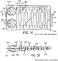
30 ist eine nicht zur Erfindung gehörende Draufsicht einer siebenschichtigen Spannblase. -
31 ist eine Querschnittsansichtder Blase von 30 entlang der Linie31-31 . -
32 ist eine nicht zur Erfindung gehörende Seitenansicht einer Vielfolienschichtblase mit eingezogenem Seitenwandsaum, der von inneren Folienschichten gebildet ist. -
33 ist eine perspektivische Ansicht derBlase von 32 . -
34 ist eine Querschnittsansichtder Blase von 32 entlang der Linie34-34 von 32 . -
35 ist eine Teilquerschnittsansichtder Blase von 32 vor dem Schweißen und Aufblasen, sowie mit schematischen Darstellungen von Schweißstellen. -
36 ist eine nicht zur Erfindung gehörende perspektivische Darstellung einer Vielfolienschichtblase mit einem mittigen eingezogenen Seitenwandsaum, der aus gesonderten Seitenwandelementen gestaltet ist. -
37 ist eine Draufsichtder Blase von 36 . -
38 ist eine Seitenansicht von einer Seite derBlase von 36 . -
39 ist eine Seitenansicht von einer Seite derBlase von 36 , die sich im Wesentlichen senkrecht zu der in38 dargestellten Seite erstreckt. -
40 ist eine Teilquerschnittsansichtder Blase von 36 vor dem Schweißen und Aufblasen mit schematischer Darstellung von Schweißstellen. -
41 ist eine Teilquerschnittsansichtder Blase von 36 entlang der Linie41-41 in37 . -
42 ist eine perspektivische Ansicht einer erfindungsgemäßen Vielfolienschichtblase mit einem mittigen eingezogenen Seitenwandsaum, der aus gesonderten Seitenwandelementen in Übereinstimmung mit einem weiteren Ausführungsbeispiel der vorliegenden Erfindung gebildet ist. -
43 ist eine Draufsichtder Blase von 42 . -
44 ist eine Seitenansicht einer Seite derBlase von 42 . -
45 ist eine Seitenansicht einer Seite derBlase von 42 , die sich im Wesentlichen senkrecht zu der in44 dargestellten Seite erstreckt. -
46 ist eine Teilquerschnittsansichtder Blase von 42 entlang der Linie46-46 von 43 . -
47 ist eine Teilquerschnittsansichtder Blase von 42 vor dem Schweißen und Aufblasen mit schematischen Darstellungen von Schweißstellen. -
48 ist eine Seitenansicht einer Vielfolienschichtblase, die einen versetzten eingezogenen Seitenwandsaum aufweist, der aus gesonderten Seitenwandelementen in Übereinstimmnung mit einem anderen Ausführungsbeispiel der vorliegenden Erfindung gebildet ist. -
49 ist eine perspektivische Ansicht derBlase von 48 . -
50 ist eine Querschnittsansichtder Blase von 48 entlang der Linie50-50 in48 . -
51 ist eine Teilquerschnittsansichtder Blase von 48 vor dem Schweißen und Aufblasen mit schematischen Darstellungen der Schweißstellen. -
52 ist eine perspektivische Ansicht einer Vielfolienschichtblase mit einem eingezogenen Saum in dem Bogen- bzw. Fußgewölbebereich, in Übereinstimmung mit einem anderen Ausführungsbeispiel der vorliegenden Erfindung. -
53 ist eine Seitenansicht der Bogenseite derBlase von 52 . -
54 ist eine Draufsichtder Blase von 52 . -
55 ist eine Teilansicht entlang der Linie55-55 von 54 . -
56 ist eine Querschnittsansicht entlang der Linie56-56 von 54 . -
57A bis57F sind schaubildliche Darstellungen einer Blasenaufblastechnik.
-
1 Figure 11 is a perspective view of a bladder constructed of three film layers according to an embodiment of the present invention. -
2 is a top view of the bubble of1 , -
3 is a cross-sectional view of the bubble along the line3-3 from2 , -
4 Figure 11 is a perspective view of another bladder constructed of three film layers to show the contours of the outer surfaces by locating the joints. -
5 is a top view of the bubble of4 , -
6 is a cross-sectional view of the bubble along the line6-6 from5 , -
7 Figure 11 is a perspective view of a whole-foot bladder constructed of three film layers in accordance with another embodiment of the present invention. -
8th is a top view of the bubble of7 , -
9 is a cross-sectional view of the bubble along the line9-9 from8th , -
10 is a cross-sectional view of the bubble along the line10-10 from8th , -
11 is a not belonging to the invention perspective view of a heel bladder, which is composed of four film layers. -
12 is a top view of the bubble of11 , -
13 is a cross-sectional view of the bubble along the line13-13 from12 , -
14 Figure 5 is a disassembled view of the orientation of an inner bladder relative to outer film layers of a bladder. -
15 is a top view of the bubble of14 , sealed and inflated. -
16 is a cross-sectional view of the bubble along the line16-16 from15 , -
17 is a cross-sectional view of the bubble along the line17-17 from15 , -
18 Figure 5 is a disassembled view of the orientation of an inner bladder relative to outer film layers of a bladder. -
19 is a top view of the bubble of18 , sealed and inflated. -
20 is a cross-sectional view of the bubble along the line20-20 from19 , -
21 is a cross-sectional view of the bubble along the line21-21 from19 , -
22 is a non-related schematic representation of a portion of a heel bladder in its static state. -
23 is a schematic representation of the section of22 , shown under load. -
24 is an exploded perspective view of a shoe, the bubble of theinvention 7 in a sole assortment. -
25A and25B are schematic diagrams of a five-layer bladder not belonging to the invention. -
26A and26B are schematic diagrams of a six-layer bladder not belonging to the invention. -
27 FIG. 10 is a plan view of a complex contoured three layer collapsible adapted for use within a larger bladder in accordance with the present invention. FIG. -
28 is a side view of the bubble of27 , -
29 is a perspective view of the bubble of27 , -
30 is a not belonging to the invention top view of a seven-layer clamping bubble. -
31 is a cross-sectional view of the bubble of30 along the line31-31 , -
32 is a not belonging to the invention side view of a multilayer film bubble with retracted sidewalls, which is formed by inner film layers. -
33 is a perspective view of the bubble of32 , -
34 is a cross-sectional view of the bubble of32 along the line34-34 from32 , -
35 is a partial cross-sectional view of the bubble of32 before welding and inflation, as well as with schematic representations of welds. -
36 is a not belonging to the invention perspective view of a multilayer film bubble with a central retracted sidewall, which is designed from separate side wall panels. -
37 is a top view of the bubble of36 , -
38 is a side view of one side of the bubble of36 , -
39 is a side view of one side of the bubble of36 which is substantially perpendicular to the in38 extends shown side. -
40 is a partial cross-sectional view of the bubble of36 before welding and inflation with schematic representation of welds. -
41 is a partial cross-sectional view of the bubble of36 along the line41-41 in37 , -
42 Figure 3 is a perspective view of a multilayer film bladder according to the present invention having a central retracted sidewall formed from separate sidewall members in accordance with another embodiment of the present invention. -
43 is a top view of the bubble of42 , -
44 is a side view of one side of the bubble of42 , -
45 is a side view of one side of the bubble of42 which is substantially perpendicular to the in44 extends shown side. -
46 is a partial cross-sectional view of the bubble of42 along the line46-46 from43 , -
47 is a partial cross-sectional view of the bubble of42 before welding and inflation with schematic representations of welds. -
48 Figure 10 is a side view of a multilayer film bladder having an offset retracted sidewall formed from separate sidewall members in accordance with another embodiment of the present invention. -
49 is a perspective view of the bubble of48 , -
50 is a cross-sectional view of the bubble of48 along the line50-50 in48 , -
51 is a partial cross-sectional view of the bubble of48 before welding and inflation with schematic representations of welds. -
52 Figure 10 is a perspective view of a multi-layered bladder with a hemmed in hem in the arch area, in accordance with another embodiment of the present invention. -
53 is a side view of the bow side of the bubble of52 , -
54 is a top view of the bubble of52 , -
55 is a partial view along the line55-55 from54 , -
56 is a cross-sectional view along the line56-56 from54 , -
57A to57F are perspective views of a bubble inflation technique.
Es wird Bezug genommen auf die Figuren, die einige Abwandlungen bevorzugter Ausführungsformen von Vielfolienschichtblasen (multiple film layer bladders) zeigen. Wegen der komplexen Geometrie von Vielfolienschichtblasen sind die perspektivischen Ansichten der Blasen aus Gründen der Klarheit in einigen Fällen dargestellt, als ob die äußeren Folienschichten undurchsichtig sind in Verbindung mit einem inneren Aufbau, der im Querschnitt dargestellt ist. Es wird darauf hingewiesen, daß die Folienschichten durchsichtig, getönt oder undurchsichtig oder eine gewisse Kombination von Folien von verschiedenem Aussehen sind. Die Bezeichnung „Verbindungsstelle“ nimmt in den Anmeldungsunterlagen durchgehend in allgemeiner Form Bezug auf Anbringungs- bzw. Zusammenfügungsorte zwischen jeglichen der Folienschichten. Eine in den Zeichnungen verwendete Maßnahme besteht darin, daß Verbindungsstellen nur mit einer Umriß- oder Außenlinie oder als eine von Bogen umgebene bzw. eingehüllte Umriß- oder Außenlinie dargestellt sind. Die Stellen mit Bogen stellen eine Verbindung zwischen einer inneren Folienschicht und einer äußeren Folienschicht dar, die dem Betrachter am nächsten liegt. Die Stellen, die nur eine Verbindungs-Außenlinie zeigen, geben eine Verbindung zwischen zwei inneren Folienschichten an oder zwischen einer inneren Folienschicht und einer äußeren Folienschicht, die vom Betrachter am weitesten entfernt liegt. Die Verbindungsstellen können die Form kreisförmiger Punkte, Streifen, gestreckter Linien oder jegliche andere geometrische Gestalt haben, die dazu benutzt wird, um eine der Folienschichten an einer anderen anzubringen. Wie noch von den verschiedenen bevorzugten Ausführungsformen deutlich wird, sind die Außenschichten, die die Umhüllung bzw. Hülle bilden, mindestens längs des Umfangs aneinander angebracht, und jegliche Anzahl von Innenschichten sind aneinander oder an einer Außenschicht angebracht.Reference is made to the figures, which show some modifications of preferred embodiments of multiple film layer bladders. Because of the complex geometry of multilayer film bladders, the perspective views of the bladders are shown in some cases for the sake of clarity, as if the outer film layers are opaque in combination with an internal structure shown in cross-section. It should be noted that the film layers are transparent, tinted or opaque or some combination of films of different appearance. The term "joint" throughout the application documents refers generally to mounting locations between any of the film layers. One measure used in the drawings is that joints are shown only with an outline or outline, or as a contoured outline surrounded by arcs. The arcuate locations provide a connection between an inner film layer and an outer film layer closest to the viewer. The locations showing only a compound outline indicate a connection between two inner layers of film, or between an inner layer of film and an outer layer of film furthest away from the viewer. The joints may be in the form of circular dots, stripes, elongated lines, or any other geometric shape used to attach one of the film layers to another. As will become apparent from the various preferred embodiments, the outer layers forming the envelope are attached to one another at least along the circumference, and any number of inner layers are attached to each other or to an outer layer.
Alle Figuren zeigen Gestaltungen von Blasen oder Teile von Blasen, die abgedichtet und mit einem Strömungsmedium gefüllt sind. Das bedeutet, daß die Darstellungen mit Strömungsmedium gefüllte Formkörper zeigen, die ihre Form aufgrund des Musters bzw. der Verteilung der Befestigungen der flachen Folienschichten erhalten.All figures show configurations of bubbles or parts of bubbles which are sealed and filled with a flow medium. That is, the flow medium representations show filled moldings which are given their shape due to the pattern or distribution of the attachments of the flat film layers.
Aus Gründen einer Vereinfachung der Erklärungen wird auf verschiedene Merkmale des Fußes eines Trägers Bezug genommen, um Richtungen oder Stellen bzw. Orte an den Blasen zu erklären, die beschrieben werden. Der Zeh, Vorderfuß, Mittelfuß, Fußwölbung und Ferse werden in ihrer üblichen Bedeutung benutzt. „Medial“ bezieht sich auf die Seiten der Füße eines Trägers, die einander gegenüberliegen würden, und „lateral“ bezieht sich auf die Außenseite des Fußes des Trägers.For ease of explanation, reference will be made to various features of a wearer's foot to explain directions or locations on the bladders being described. The toe, forefoot, metatarsus, arch and heel are used in their usual meaning. "Medial" refers to the sides of the feet of a wearer that would face each other, and "lateral" refers to the outside of the wearer's foot.
Ein bevorzugtes Ausführungsbeispiel einer Vielfolienschichtenblase
Eine andere aus drei Folienschichten bestehende Blase
Eine Dreifolienschichtblase für einen ganzen Fuß ist in den
Dreifolienblasen bilden zwei Schichten mit Strömungsmedium, die der Blase dämpfende und reaktive Merkmale verleihen und die Abhängigkeit von jeglichem Schaum, der in der Schuhsohle verwendet ist, verringert. Die zwei mit Strömungsmedium gefüllten Schichten können gleichen Druck oder verschiedene Drücke aufweisen, je nach dem besonderen Dämpfungsprofil, das gewünscht wird. Wenn z.B. eine flachere mit Strömungsmedium gefüllte und unter Druck stehende Schicht äußerst nahe am Fuß des Trägers angeordnet wird, würde die Schuhsohle dem Träger ein weicheres oder elastischeres bzw. federnderes Gefühl vermitteln. Je nachdem, für welche Aktivität der Schuh entworfen ist, kann der Druck der mit Strömungsmedium gefüllten Schichten angepaßt und sehr fein eingestellt werden, um ein Maximum an Reaktion und Gefühl zu erhalten. Das Füllen der Blase wird durch einen Ventilschaft erreicht, der Verbindung zu allen mit Strömungsmedium gefüllten Schichten hat. Wenn die mit Strömungsmedium gefüllten Schichten ihren gewünschten Druck erreichen, können die Folienschichten, die diese mit Strömungsmedium gefüllte Schicht bilden, an dem Ventilschaft abgedichtet werden, um ein weiteres Aufblasen bzw. Füllen dieser mit Strömungsmedium gefüllten Schicht zu beenden, während andere Schichten weiter mit Druck beaufschlagt werden. Nacheinander erfolgendes Abdichten geeigneter Folienschichten im Ventilbereich ermöglicht die Erreichung vorgegebener Drücke der verschiedenen mit Strömungsmedium gefüllten Schichten der Blase. Dieses Prinzip kann auf jede Anzahl von Folienschichten angewendet werden.Tri-foil bladders form two layers of flow medium which impart damping and reactive characteristics to the bladder and reduce dependence on any foam used in the shoe sole. The two fluid-filled layers may have equal pressure or different pressures, depending on the particular damping profile desired. For example, if a shallower fluid-filled and pressurized layer is placed extremely close to the foot of the wearer, the shoe sole would provide the wearer with a softer or more elastic or elastic layer. convey a more springy feeling. Depending on what activity the shoe is designed for, the pressure of the fluid-filled layers can be adjusted and adjusted very finely to obtain maximum response and feel. The filling of the bladder is achieved by a valve stem having connection to all fluid-filled layers. As the fluid-filled layers reach their desired pressure, the film layers forming this fluid-filled layer may be sealed to the valve stem to terminate further inflation of this fluid-filled layer, while other layers continue to pressurize be charged. Successive sealing of suitable film layers in the valve area enables the attainment of predetermined pressures of the various fluid-filled layers of the bladder. This principle can be applied to any number of film layers.
Eine alternative Einfüll- bzw. Aufblastechnik ist in den
In den
Vier Folienschichten haben eine Blase mit drei vertikal übereinander gesetzten mit Strömungsmedium gefüllten Schichten durch jegliches Dämpfungsprofil zur Folge: eine erste äußere Schicht
Neben der Unterteilung in drei vertikal übereinanderliegende mit Strömungsmedium gefüllte Schichten, die nicht zur Erfindung gehören, könnte die Blase
In diesem besonderen Ausführungsbeispiel, das nicht zur Erfindung gehört, ist die Blase
Mit den vorstehenden Ausführungen stimmt überein, daß die Anordnung der Verbindungsstellen zwischen den inneren Folienschichten selbst und den Verbindungsstellen zwischen einer der inneren Folienschichten mit einer benachbarten äußeren Folienschicht die Dicke und das Profil der entstehenden Blase bestimmt. Darüber hinaus kann die besondere Form der Verbindungsstellen so angepaßt werden, daß innere mit Strömungsmedium gefüllte Kammern entstehen.It is consistent with the above discussion that the location of the joints between the inner film layers themselves and the junctions between one of the inner film layers with an adjacent outer film layer determines the thickness and profile of the resulting bladder. In addition, the particular shape of the joints can be adapted so that inner filled with fluid flow chambers arise.
Die bisher beschriebenen Ausführungsbeispiele bilden Teilfußblasen von relativ einfachem Aufbau, wobei kreisrunde Schweißpunkte als Verbindungsstellen verwendet werden. Die Prinzipien einer Vielfolienschicht und einer Blase aus zwei mit Strömungsmedium gefüllten Schichten können auf jegliche geeignete Blasenform und Anwendung benutzt werden, wie aus den nachfolgend beschriebenen Ausführungsbeispielen hervorgeht.The embodiments described so far form Teilfußblasen relatively simple structure, with circular welds are used as joints. The principles of a multilayer film and a bladder of two fluid-filled layers can be applied to any suitable blister shape and application, as will be apparent from the embodiments described below.
Eine nicht zur Erfindung gehörende Ganzfußblase
Die Blase
Die äußere Folienschicht
Die
Beispielsweise ist im Fersenbereich (
In dem Vorderfußbereich (
Es ergibt sich, daß jegliche Unterschiede in den Lagen der Verbindungsstellen in einer vertikalen Überlagerung einiger Teilkammern oder von Teilen von Teilkammern in jeder vorhandenen Schicht zum Ergebnis hat. Im Vorderfußbereich sind obere und untere Schichten
Wie im einzelnen in den
Durch eine Veränderung des Druckniveaus der mit Strömungsmedium gefüllten Schichten kann jegliches gewünschte Dämpfungs- bzw. Polsterungsprofil erreicht werden. Wenn man beispielsweise das Dämpfungs- und Polsterungsprofil von
Wie am besten aus den
In Übereinstimmung mit den der Erfindung zugrundeliegenden Prinzipien können die Verbindungsstellen eingerichtet werden, um die Höhe und das Maß des Polsterprofils bzw. des Dämpfungsprofils überall an der Blase zu verändern. Die Ausgestaltung des Ortes der Verbindungsstellen kann auch variiert werden, um eine Vielzahl von Kammern im Bereich jeglicher mit Strömungsmedium gefüllten Schicht oder zwischen mit Strömungsmedium gefüllten Schichten zu erhalten.In accordance with the principles underlying the invention, the joints may be arranged to vary the height and the dimension of the cushioning profile or damping profile throughout the bladder. The configuration of the location of the joints may also be varied to obtain a plurality of chambers in the area of any fluid-filled layer or between fluid-filled layers.
Eine andere für den ganzen Fuß bestimmte, nicht zur Erfindung gehörende Blase
Die
Wenn man beispielsweise den Fersenbereich in
Ähnlich wie bei dem nicht zur Erfindung gehörenden Ausführungsbeispiel, das in den
Einzelheiten des Polster- bzw. Dämpfungsprofils des Vorderfußes und die darin enthaltenen gesonderten Kammern (
Das Polsterprofil im Fersenbereich im Einzelnen sowie die hier vorhandenen gesonderten Kammern sind in der nicht zur Erfindung gehörenden
Die nicht zur Erfindung gehörende Blase
In Übereinstimmung mit den Grundsätzen der Erfindung können die Verbindungsstellen in entsprechender Weise angeordnet werden, um die Höhe des Polsterprofils irgendwo entlang und an der Blase zu verändern. Die Gestaltung des Ortes der Verbindungsstellen kann ebenfalls verändert werden, um eine Vielzahl von Kammern bzw. Vielfachkammern an jeglicher mit Strömungsmedium gefüllter Schicht oder zwischen mit Strömungsmedium gefüllten Schichten zu erreichen.In accordance with the principles of the invention, the joints may be similarly arranged to vary the height of the cushioning profile anywhere along and at the bladder. The location of the joints may also be altered to achieve a plurality of chambers or multiple chambers on any fluid-filled or fluid-filled layers.
Ein Beispiel eines weich-hart-weich Polsterprofils oder auch Dämpfungsprofils in einer aus vier Folienschichten bestehenden Blase ist schematisch in den nicht zur Erfindung gehörenden
Eine Blase
Auch wenn Blasen mit drei Folienschichten im Einzelnen beschrieben wurden, bezieht sich die Erfindung ganz allgemein NICHT auf Vielfolienschichten, die mit Strömungsmedium gefüllte Schichten zwischen sich bilden. Die Darstellungen von Blasen mit drei Folienschichten verdeutlichen das Prinzip der Erfindung, wobei nur drei Folienschichten und zwei mit Strömungsmedium gefüllte Schichten von der vorliegenden Erfindung erfaßt werden.Although blisters having three film layers have been described in detail, the invention generally does NOT refer to multilayer films that form fluid-filled layers therebetween. The three layer film blister representations illustrate the principle of the invention wherein only three film layers and two fluid-filled layers are covered by the present invention.
Blasen aus fünf und sechs Folienschichten zählen nicht zur Erfindung. Sie sind entwickelt und hergestellt worden, aber sie lassen sich aufgrund ihrer Komplexität in Patentzeichnungen nur sehr schwierig darstellen. Schematische Querschnittsansichten von Blasen mit fünf und sechs Folienschichten sind in den nicht zur Erfindung gehörenden
Die aus sechs Schichten bestehende, nicht zur Erfindung gehörende Blase von
Die
Eine Dreischichtblase wie die Blase
Wenn -nicht zur Erfindung gehörend- vier oder mehr Folienschichten in dem Aufbau benutzt werden, ist ein alternatives inhaltliches Prinzip, das einer Blase, die eine Gruppe von mit Strömungsmedium gefüllten inneren Kammern und zwei äußeren Folienschichten umfaßt, die über den inneren Kammern liegen und an diesen befestigt sind an ausgewählten Verbindungsstellen, um ein oder zwei äußere Kammern zu schaffen. Dieser Aufbau ergibt eine stabile planare Blase, in der die äußeren Folienschichten die inneren Kammern beeinflussen bzw. deren Wirkung verringern, besonders, wenn die inneren Kammern einen höheren Druck aufweisen als die äußere Kammer. Die Kammern mit höherem Druck, die aus flachen Folien gebildet sind, können auch zum Verwinden neigen, und das Hinzufügen äußerer Folien und einer äußeren Kammer mit niedrigerem Druck würde das Verwinden verhindern durch ein Ausgleichen der statischen Belastungen der Blase, wenn sie mit Strömungsmedium gefüllt ist.When not belonging to the invention, four or more film layers are used in the construction, an alternative content-related principle is that of a bubble comprising a group of fluid-filled inner chambers and two outer film layers overlying the inner chambers these are attached at selected joints to create one or two outer chambers. This construction provides a stable planar bubble in which the outer film layers affect the inner chambers or reduce their effect, especially when the inner chambers have a higher pressure than the outer chamber. The higher pressure chambers formed from flat sheets may also tend to twist, and the addition of outer sheets and an outer lower pressure chamber would prevent warping by equalizing the static loads on the bubble when filled with flow medium ,
Die vielschichten Folienblasen der vorliegenden Erfindung können auch mit einem eingezogenen Saum längs der Seitenwand versehen sein. Wie in den nicht zur Erfindung gehörenden
Die Blase
Wie man am besten der nicht zur Erfindung gehörenden
Die Blase
Die äußeren Grenzschichten
Die
Die Blase
Ein Spannglied
Die erfindungsgemäße Blase
Die
Die Blase
Die Außenwände der Blase
Der eingezogene Saum
Dies trifft insbesondere zu, wenn der Saum
Die
Der eingezogene Saum
Was die Materialien für die hier vorgestellten Blasen anbelangt, können die oberen und unteren Grenzblätter bzw. -bögen, die Seitenwandelemente und die inneren Schichten gebildet werden aus gleichen oder verschiedenen Grenzmaterialien wie thermoplastischen Elastomerfolien, indem man bekannte Verfahren anwendet. Thermoplastische Elastomerfolien, die im Zusammenhang mit der vorliegenden Erfindung verwendet werden können, enthalten Polyester-Polyurethan, Polyether-Polyurethan sowie eine gegossene extrudierte ester-basierte Polyurethanfolie mit einer Shore-Härte „
In Übereinstimmung mit der vorliegenden Erfindung kann die Vielfolienschichtblase gebildet werden mit Grenzmaterialien, die die besonderen Erfordernisse oder Spezifikationen von jedem ihrer Teile erfüllen. Die vorliegende Erfindung gestattet die Bildung der oberen Schicht aus einem ersten Grenzmaterial, der unteren Schicht aus einem zweiten Grenzmaterial und jedes Teils der Seitenwand oder Seitenwände, die zu bilden sind, aus einem dritten Grenzmaterial. Auch die Seitenwandteile können jeweils aus verschiedenen Grenzmaterialien gebildet werden. Wie oben erläutert ist, werden die inneren Grenzblätter oder Grenzbögen und die Seitenwandteile aus dem gleichen Grenzmaterial gebildet, wenn der einwärts gerichtete bzw. eingezogene Saum gebildet wird durch Verbinden der Grenzenden der inneren Grenzblätter oder Grenzbögen an den äußeren Grenzbögen bzw. Grenzblättern in Nachbarschaft einer Schweißung der inneren Bögen bzw. Blätter. Daraus folgt, wenn die inneren Grenzbögen oder Grenzblätter gebildet sind aus einem anderen Material als die äußeren Grenzbögen bzw. Grenzblätter, daß die Seitenwände gebildet sind aus dem gleichen Material wie das Material der inneren Grenzbögen bzw. inneren Grenzblätter. Auch wenn die inneren Grenzblätter oder Grenzbögen aus verschiedenen Materialien gebildet sind, müssen die Seitenwandteile zwecks Kompatibilität ebenfalls aus verschiedenen Materialien gebildet werden.In accordance with the present invention, the multilayer film bladder can be formed with barrier materials that meet the particular requirements or specifications of each of its parts. The present invention permits the formation of the upper layer of a first boundary material, the lower layer of a second boundary material, and each portion of the sidewall or sidewalls to be formed of a third boundary material. The side wall parts can each be formed from different boundary materials. As explained above, the inner boundary sheets and the side wall portions are formed of the same boundary material when the inward hem is formed by bonding the boundary edges of the inner boundary sheets to the outer boundary sheets adjacent to a weld the inner arches or leaves. As a result, when the inner boundary sheets or boundary sheets are formed of a material other than the outer boundary sheets, the side walls are formed of the same material as the material of the inner boundary sheets. Even if the inner boundary sheets or boundary sheets are formed of different materials, the side wall parts must also be formed of different materials for compatibility.
Wenn die inneren Schichten durch ein Blasenfenster sichtbar sein sollen, muß die Seitenwand sehr wahrscheinlich aus einem transparenten Material bestehen, um ein Maximum an Sichtbarkeit zu erreichen. In den in den Figuren dargestellten Beispielen mit eingezogenem Saum brauchen die oberen und unteren Schichten nicht aus einem transparenten Material zu bestehen. Stattdessen können sie jeweils aus undurchsichtigem Grenzmaterial mit gleicher oder verschiedener Dicke gebildet sein. In ähnlicher Weise können die Seitenwandstücke aus einem dickeren oder dünneren transparenten Material bestehen, so daß das Innere sichtbar ist. Die Dicke der Seitenwand
Nach der vorliegenden Erfindung können die Grenzmaterialien, die für jeden Teil der Blase benutzt werden, vorausbestimmt werden, um nur die spezifischen Erfordernisse von diesem Teil zu erfüllen. Beispielsweise, wenn die oberen und unteren Schichten ein undurchsichtiges, relativ dünnes, flexibles Grenzmaterial benutzen, können die exponierten Seitenwände aus einem dickeren, steiferen sowie transparenten Grenzmaterial hergestellt werden. Im Gegensatz zur Industriepraxis würde dann nur der Teil der Blase, der im Blasenfenster gezeigt wird, aus dem steiferen transparenten Material hergestellt. Auch die Seitenwände können mit einer vorgeformten Gestalt oder mit größerer Steifigkeit gegenüber vertikaler Kompression hergestellt werden, um dem Druck in der Blase oder individuellen Druckbereichen innerhalb der Blase zu entsprechen. Die Materialien, die für die Seitenwände gewählt sind, können auch dazu benutzt werden, um Teile des Schuhwerks zu versteifen, das einer Druck- und Scherbeanspruchung unterliegt, wie beispielsweise die mediale Seite der Ferse. Ein wirtschaftlicher Vorteil wird ebenfalls erzielt. Indem man die oberen und unteren Schichten nicht aus dem gleichen Material wie die Seitenwände herstellt, können die Herstellungskosten einer Blase gesenkt werden. Nach der vorliegenden Erfindung werden sehr teure Materialien nur benutzt, wo sie gebraucht werden, nicht aber an der gesamten Blase.According to the present invention, the boundary materials used for each part of the bubble can be predetermined to meet only the specific requirements of that part. For example, if the upper and lower layers use an opaque, relatively thin, flexible barrier material, the exposed sidewalls can be made from a thicker, stiffer, and transparent barrier material. In contrast to industry practice, only the part of the bladder shown in the bladder window would then be made of the stiffer transparent material. Also, the sidewalls can be made with a preformed shape or with greater stiffness to vertical compression to suit the pressure in the bladder or individual pressure areas within the bladder. The materials chosen for the sidewalls can also be used to stiffen parts of the footwear that are subject to compressive and shear stress, such as the medial side of the heel. An economic advantage is also achieved. By not making the upper and lower layers of the same material as the sidewalls, the cost of producing a bladder can be reduced. According to the present invention, very expensive materials are used only where they are needed, but not on the entire bladder.
Die Blase wird vorzugsweise aufgeblasen mit einem gasförmigen Strömungsmedium wie beispielsweise Hexafluorethan, Schwefel-Hexafluorid, Stickstoff, Luft oder andere Gase wie diejenigen, die in den vorerwähnten Patenten '156, '945, '029 oder '176 (RUDY) oder '065 (Mitchell et al.) offenbart und beschrieben sind.The bubble is preferably inflated with a gaseous flow medium such as hexafluoroethane, sulfur hexafluoride, nitrogen, air or other gases such as those described in the aforementioned '156,' 945, '029 or' 176 (RUDY) or '065 (Mitchell et al.) are disclosed and described.
Das Verfahren zur Bildung einer Blase mit mindestens einem einwärts gerichteten bzw. eingezogenen Seitenwandsaum nach der vorliegenden Erfindung schließt die Auswahl des Materials für jedes Teil auf der Basis mindestens der Kräfte und Spannungen, denen das Teil unterworfen wird, und die Leistungsdaten ein, die das Teil erreichen soll. Auch das ästhetische Aussehen jedes Teils der Blase muß berücksichtigt werden. Beispielsweise, wenn das innere der Blase sichtbar gemacht werden soll, ist es erforderlich, die exponierten Seitenwände bzw. die exponierte Seitenwand aus einem transparenten Material herzustellen, das den gewünschten Durchblick bzw. Anblick gestattet. Das transparente Material muß jedoch, wie schon oben erläutert wurde, auch ausreichend kräftig sein, um ein Ab- oder Ausreißen aufgrund von von außen ausgeübten Kräften zu vermeiden und um Biegespannungen aufzunehmen, die während eines Schrittes bzw. eines Laufs des Benutzers auf die Blase ausgeübt werden. Während die Seitenwände transparent sind und eine Dicke von 0,020 bis 0,100 inch aufweisen, sind die oberen und unteren Schichten der Blase aus undurchsichtigem Material gebildet mit einer Dicke von 0,005 bis 0,050 inch, um die besonderen Notwendigkeiten ihrer am Ende erfolgenden Anordnung im Schuh zu erfüllen, wie oben erläutert ist. Wenn eine Blasengestaltung gewünscht wird, die ein Sichtbarmachen nur von der unteren Oberfläche verschafft, können die oberen und unteren Folien verschieden sein. Eine klare Folie mit einer Dicke im Bereich von .020''-.100'' könnte für die untere Fläche und eine einfache undurchsichtige Folie von .005'' -.010'' könnte verwendet werden für die oberen und seitlichen Flächen.The method of forming a bladder having at least one inwardly drawn sidewall space according to the present invention includes selecting the material for each part based on at least the forces and stresses to which the part is subjected and the performance data that is the part should reach. Also, the aesthetic appearance of each part of the bladder must be considered. For example, if the interior of the bladder is to be visualized, it is necessary to make the exposed sidewalls, or exposed sidewall, of a transparent material that permits the desired view. However, as already explained above, the transparent material must also be sufficiently strong to avoid tearing or tearing due to external forces and to absorb bending stresses exerted on the bladder during a user's run become. While the sidewalls are transparent and have a thickness of 0.020 to 0.100 inches, the top and bottom layers of the bladder are formed of opaque material 0.005 to 0.050 inches thick to meet the particular needs of their final placement in the shoe. as explained above. If a bladder design is desired that provides visibility only from the bottom surface, the top and bottom foils may be different. A clear film having a thickness in the range of .020 "-100" could be used for the bottom surface and a simple opaque film of .005 "-010" could be used for the top and side surfaces.
Nachdem die Größe und die Typen des Materials bestimmt sind, werden die Grenzbögen bzw. Grenzblätter, die die obere Schicht, die untere Schicht und die Seitenwände bilden, hergestellt, indem man sich bekannter Schneid- und Formtechniken bedient. Die flachen, geformten Blätter oder Bogen werden dann so angeordnet, daß ihre Umfangsränder den Umfang der Blase bilden. Die Seitenwandteile werden zwischen den oberen und unteren Grenzschichten angeordnet und daran befestigt, indem man bekannte Techniken wie Hochfrequenzschweißen anwendet. Die Grenzbögen bzw. Grenzblätter, die zur Bildung der Blasen benutzt werden, werden selektiv mit einem Schweißverhinderungsmaterial behandelt, das die Entstehung von Hochfrequenzschweißungen verhindert. Beispiele von Schweißverhinderern sind Teflon®-Beschichtungen und Teflon® beschichtete Gewebe oder Streifen wie Du Pont Teflon® #49 oder #57, die überall dort angeordnet werden können, wo eine Schweißung verhindert werden soll. Andere herkömmliche Schweißverhinderer oder Schweißblockierer wie Bänder, die von Firma 3M hergestellt werden, sind Scotch „Magic Mending“ Band und Highland 3710 Box Sealing Band oder ein von Faron hergestelltes Band einschließlich Kapton PSA Band oder Teflon® PSA Band, Fluoroglide „FB“ Spray-Gleitmittel von Norton oder Überzüge auf Wasserbasis von Graphic Sciences entweder mit Teflon® oder Parafin, einem Styrolacrylpolymer können benutzt werden zwischen den Schichten und Seitenwänden, um sicherzustellen, daß nur die dafür bestimmten Teile der Blase miteinander verbunden werden. Die Inhibitoren werden entweder nach dem Schweißen entfernt oder in dem Hochfrequenzschweißprozeß verbraucht.Once the size and types of material have been determined, the boundary sheets forming the top, bottom and sidewalls are made using known cutting and molding techniques. The flat, shaped sheets or sheets are then placed so that their peripheral edges form the periphery of the bubble. The sidewall portions are positioned and secured between the upper and lower barrier layers using known techniques such as high frequency welding. The boundary sheets used to form the bubbles are selectively treated with a weld prevention material which prevents the generation of high frequency welds. Examples of welding preventers are Teflon ® coatings and Teflon ® coated fabrics or strips, such as Du Pont Teflon ® # 49 or # 57, which can be placed anywhere where a weld is to be prevented. Other conventional welding preventer or sweat blocker such as tapes, which are manufactured by 3M, are Scotch "Magic Mending" tape and Highland 3710 Box Sealing tape or a product manufactured by Faron band including Kapton PSA tape or Teflon ® PSA tape Fluoroglide "FB" spray lubricant by Norton, or water-based coatings by Graphic Sciences with either Teflon ® or paraffin, a styrene acrylic polymer may be used between the layers and sidewalls to insure that only the designated portions of the bladder are joined together. The inhibitors are either removed after welding or consumed in the high frequency welding process.
Um jede der hier beschriebenen Blasen herzustellen, wird zunächst das Schweißmuster für jede Schicht festgelegt und auf den Bögen bzw. Blättern markiert. Das Schweißmuster würde dem Muster der Verbindungsstellen an der besonderen Seite einer Schicht entsprechen. Dieses Muster ist auf den Bögen bzw. Blättern entweder positiv oder negativ mittels Siebdruck, Tintendruck oder ein Übertragungsverfahren markiert. Die Markierung kann sichtbar sein wie bei Benutzung von Tinte, oder sie kann auch unsichtbar sein wie bei einem Übertragungsverfahren, mit dem Schweißverhinderungsmaterial auf die Seite der Folienschicht aufgetragen wird. Es sei darauf hingewiesen, daß die Schweißverhinderungsmaterialien allgemein das negative Bild der gewünschten Verbindungsstellen sein würden. Die Anwendung von Schweißverhinderungsmaterial auf der Schicht kann ein von dem Markieren der Verbindungsstellen separater Verfahrensschritt sein. Die Vielfalt der Formen und Gestaltungen der Verbindungsstellen ist nur begrenzt durch die Anwendung von Schweißverhinderungsmaterial an den Schichten.To make each of the bubbles described herein, the sweat pattern for each layer is first determined and marked on the sheets. The welding pattern would correspond to the pattern of joints on the particular side of a layer. This pattern is marked on the sheets either positively or negatively by screen printing, ink printing or a transfer process. The mark may be visible as when using ink, or it may also be invisible, as in a transfer process that applies sweat-preventing material to the side of the film layer. It should be noted that the weld prevention materials would generally be the negative image of the desired joints. The application of weld prevention material to the layer may be a separate step from marking the joints. The variety of shapes and configurations of joints is limited only by the application of weld prevention material to the layers.
Wenn die Verbindungsstellen in geeigneter Weise markiert sind und das Schweißverhinderungsmaterial auf die Folienschichten aufgebracht ist, wird Hochfrequenzenergie angewendet, und Hochfrequenzschweißen findet nur dort statt, wo Schichten in direktem Kontakt miteinander sind und nicht durch Schweißverhinderungsmaterial getrennt sind. Die am Umfang verlaufende Dichtung der äußersten Schichten, die dazu dienen, eine Hülle bzw. Umhüllung der Blase zu bilden, kann in einem gemeinsamen Schritt mit dem Rest der Schweißungen hergestellt werden, er kann vor und nach dem Schweißen der Verbindungsstellen gebildet werden. Wenn die Blase gebildet ist, wird sie mit Strömungsmedium gefüllt, und die Einlaßöffnung wird abgedichtet mittels einer Hochfrequenzschweißung.When the joints are appropriately marked and the weld prevention material is applied to the film layers, high frequency power is applied and high frequency welding takes place only where layers are in direct contact with each other and are not separated by weld prevention material. The peripheral seal of the outermost layers, which serve to form a sheath of the bladder, can be made in a common step with the remainder of the welds, it can be formed before and after welding the joints. When the bubble is formed, it is filled with flow medium and the inlet port is sealed by means of high frequency welding.
Während Hochfrequenzschweißen ein bevorzugtes Verfahren beim Herstellen von Vielstufenpolsterblasen gemäß der vorliegenden Erfindung ist, kann die besondere Verbindungsweise auch geändert werden. Beispielsweise kann ein Klebemittel zwischen den Folienschichten benutzt werden, ebenso wie auch andere Verbindungsmethoden durch Schmelzen, Hitze und Ultraschall.While high frequency welding is a preferred method of making multi-stage cushioning bladders according to the present invention, the particular manner of connection may also be changed. For example, an adhesive may be used between the film layers, as well as other fusion, heat and ultrasound bonding methods.
Nachdem die Blase zusammengesetzt ist und die Kammern gebildet sind, können die Blasenkammern mit bekannten Techniken aufgeblasen werden. Während eine bevorzugte Methode darin besteht, flache Materialbogen bzw. Materialblätter zu verwenden, können die Seitenwände und die äußeren und inneren Grenzschichten auch vorgeformt sein, damit sie andere bzw. abweichende Formen und Wirkungen haben, bevor sie miteinander verbunden werden, um die Blase zu bilden. Beispielsweise können Formen gebildet werden durch Warmverformung von Bogen bzw. Blättern aus Grenzschichtmaterialien.After the bladder is assembled and the chambers are formed, the bladder chambers can be inflated using known techniques. While a preferred method is to use flat sheets of material, the sidewalls and the outer and inner barrier layers may also be preformed to have different shapes and effects before being joined together to form the bladder , For example, molds may be formed by hot deformation of sheets of boundary layer materials.
Aus der vorhergehenden detaillierten Beschreibung geht hervor, daß es eine Vielzahl von Änderungen, Abwandlungen und Modifikationen der vorliegenden Erfindung gibt, die dem Fachmann bewußt werden. Es wird jedoch beabsichtigt, daß alle solche Variationen, die nicht von dem Gedanken der Erfindung abweichen, als innerhalb des Schutzumfangs liegend betrachtet werden, ausschließlich begrenzt durch die beigefügten Ansprüche.From the foregoing detailed description, it will be apparent that there are a variety of changes, modifications and alterations of the present invention which will become apparent to those skilled in the art. It is intended, however, that all such variations which do not depart from the spirit of the invention, be regarded as within the scope of the invention, are limited only by the claims appended hereto.
Claims (11)
Applications Claiming Priority (2)
| Application Number | Priority Date | Filing Date | Title |
|---|---|---|---|
| US09/526,860 US6571490B2 (en) | 2000-03-16 | 2000-03-16 | Bladder with multi-stage regionalized cushioning |
| US09/526,860 | 2000-03-16 |
Publications (1)
| Publication Number | Publication Date |
|---|---|
| DE10197410B3 true DE10197410B3 (en) | 2019-06-13 |
Family
ID=24099105
Family Applications (3)
| Application Number | Title | Priority Date | Filing Date |
|---|---|---|---|
| DE10197410.8A Expired - Lifetime DE10197410B3 (en) | 2000-03-16 | 2001-03-15 | Upholstery part for a shoe |
| DE60128672T Expired - Lifetime DE60128672T2 (en) | 2000-03-16 | 2001-03-15 | BALG WITH MULTI-STAGE DAMPING AREAS |
| DE10191079.7T Expired - Lifetime DE10191079B3 (en) | 2000-03-16 | 2001-03-15 | Bubble with a multi-level sectional upholstery |
Family Applications After (2)
| Application Number | Title | Priority Date | Filing Date |
|---|---|---|---|
| DE60128672T Expired - Lifetime DE60128672T2 (en) | 2000-03-16 | 2001-03-15 | BALG WITH MULTI-STAGE DAMPING AREAS |
| DE10191079.7T Expired - Lifetime DE10191079B3 (en) | 2000-03-16 | 2001-03-15 | Bubble with a multi-level sectional upholstery |
Country Status (7)
| Country | Link |
|---|---|
| US (2) | US6571490B2 (en) |
| EP (1) | EP1278434B1 (en) |
| CN (1) | CN1213672C (en) |
| AT (1) | ATE363217T1 (en) |
| AU (1) | AU2001250845A1 (en) |
| DE (3) | DE10197410B3 (en) |
| WO (1) | WO2001070060A2 (en) |
Families Citing this family (216)
| Publication number | Priority date | Publication date | Assignee | Title |
|---|---|---|---|---|
| US5918384A (en) | 1993-08-17 | 1999-07-06 | Akeva L.L.C. | Athletic shoe with improved sole |
| US7540099B2 (en) * | 1994-08-17 | 2009-06-02 | Akeva L.L.C. | Heel support for athletic shoe |
| US5806210A (en) | 1995-10-12 | 1998-09-15 | Akeva L.L.C. | Athletic shoe with improved heel structure |
| US7634529B2 (en) | 1996-11-29 | 2009-12-15 | Ellis Iii Frampton E | Personal and server computers having microchips with multiple processing units and internal firewalls |
| US6976321B1 (en) * | 2002-11-07 | 2005-12-20 | Nikola Lakic | Adjustable air cushion insole with additional upper chamber |
| US6601042B1 (en) | 2000-03-10 | 2003-07-29 | Robert M. Lyden | Customized article of footwear and method of conducting retail and internet business |
| US7016867B2 (en) | 2000-03-10 | 2006-03-21 | Lyden Robert M | Method of conducting business including making and selling a custom article of footwear |
| US7107235B2 (en) | 2000-03-10 | 2006-09-12 | Lyden Robert M | Method of conducting business including making and selling a custom article of footwear |
| US7752775B2 (en) | 2000-03-10 | 2010-07-13 | Lyden Robert M | Footwear with removable lasting board and cleats |
| US6681403B2 (en) | 2000-03-13 | 2004-01-27 | Robert M. Lyden | Shin-guard, helmet, and articles of protective equipment including light cure material |
| US6571490B2 (en) * | 2000-03-16 | 2003-06-03 | Nike, Inc. | Bladder with multi-stage regionalized cushioning |
| US7684786B2 (en) * | 2003-08-26 | 2010-03-23 | Nokia Corporation | Method and system for establishing a connection between network elements |
| US6755568B2 (en) * | 2000-12-21 | 2004-06-29 | Cargo Technology, Inc. | Inflatable insulating liners for shipping containers and method of manufacture |
| BRPI0306189A2 (en) * | 2002-01-04 | 2016-06-28 | New Balance Athletic Shoe Inc | shoe sole and cushioning for a shoe sole |
| US6971193B1 (en) * | 2002-03-06 | 2005-12-06 | Nike, Inc. | Bladder with high pressure replenishment reservoir |
| DE20206927U1 (en) * | 2002-05-01 | 2003-09-04 | PUMA Aktiengesellschaft Rudolf Dassler Sport, 91074 Herzogenaurach | Damping element for a shoe |
| US20040088885A1 (en) * | 2002-11-13 | 2004-05-13 | Anthony Dinkins | Air Force Two's anniversary edition |
| US7128796B2 (en) * | 2003-07-16 | 2006-10-31 | Nike, Inc. | Footwear with a sole structure incorporating a lobed fluid-filled chamber |
| US7707744B2 (en) * | 2003-07-16 | 2010-05-04 | Nike, Inc. | Footwear with a sole structure incorporating a lobed fluid-filled chamber |
| US7707745B2 (en) * | 2003-07-16 | 2010-05-04 | Nike, Inc. | Footwear with a sole structure incorporating a lobed fluid-filled chamber |
| US7562469B2 (en) | 2003-12-23 | 2009-07-21 | Nike, Inc. | Footwear with fluid-filled bladder and a reinforcing structure |
| US7086179B2 (en) | 2003-12-23 | 2006-08-08 | Nike, Inc. | Article of footwear having a fluid-filled bladder with a reinforcing structure |
| US7086180B2 (en) | 2003-12-23 | 2006-08-08 | Nike, Inc. | Article of footwear having a fluid-filled bladder with a reinforcing structure |
| US7100310B2 (en) | 2003-12-23 | 2006-09-05 | Nike, Inc. | Article of footwear having a fluid-filled bladder with a reinforcing structure |
| US7556846B2 (en) | 2003-12-23 | 2009-07-07 | Nike, Inc. | Fluid-filled bladder with a reinforcing structure |
| CN100556328C (en) * | 2003-12-23 | 2009-11-04 | 耐克国际有限公司 | Fluid-filled bladder with reinforcing structure |
| US20050240958A1 (en) * | 2004-04-21 | 2005-10-27 | Moviecrazy, Inc. | Method and apparatus for on-demand multimedia rental and sales services |
| US12290134B2 (en) * | 2004-11-22 | 2025-05-06 | Frampton E. Ellis | Footwear or orthotic sole with microprocessor control of a structural or support element with magnetorheological fluid |
| US8291618B2 (en) | 2004-11-22 | 2012-10-23 | Frampton E. Ellis | Devices with internal flexibility sipes, including siped chambers for footwear |
| US8256147B2 (en) * | 2004-11-22 | 2012-09-04 | Frampton E. Eliis | Devices with internal flexibility sipes, including siped chambers for footwear |
| US8205356B2 (en) | 2004-11-22 | 2012-06-26 | Frampton E. Ellis | Devices with internal flexibility sipes, including siped chambers for footwear |
| WO2006065225A1 (en) * | 2004-12-17 | 2006-06-22 | Osim International Ltd. | Pneumatic massaging device |
| US7669251B2 (en) * | 2005-03-21 | 2010-03-02 | Honda Motor Co., Ltd. | Impact and/or vibration absorbent material and protective articles making use thereof |
| US7254840B2 (en) * | 2005-03-21 | 2007-08-14 | Honda Motor Co., Ltd. | Impact and/or vibration absorbent material and protective glove making use thereof |
| US7622014B2 (en) | 2005-07-01 | 2009-11-24 | Reebok International Ltd. | Method for manufacturing inflatable footwear or bladders for use in inflatable articles |
| US7533477B2 (en) | 2005-10-03 | 2009-05-19 | Nike, Inc. | Article of footwear with a sole structure having fluid-filled support elements |
| US7900380B2 (en) * | 2005-10-13 | 2011-03-08 | Masterfit Enterprises Inc. | User moldable adjustable insert |
| US7451554B2 (en) * | 2005-10-19 | 2008-11-18 | Nike, Inc. | Fluid system having an expandable pump chamber |
| US7555851B2 (en) * | 2006-01-24 | 2009-07-07 | Nike, Inc. | Article of footwear having a fluid-filled chamber with flexion zones |
| US7523565B1 (en) * | 2006-02-21 | 2009-04-28 | Kuang Ming Chen | Shoes comprising air cushioning system, air lightweight system, and air pressure alert system |
| FR2898017B1 (en) * | 2006-03-03 | 2008-05-09 | Philippe Biesse | UNIVERSAL SOLE. |
| US20080110061A1 (en) * | 2006-11-11 | 2008-05-15 | South Cone, Inc. Dba Reef | Novelty footwear item with flask |
| US8176657B2 (en) * | 2006-12-04 | 2012-05-15 | Nike, Inc. | Article of footwear with tubular support structure |
| US8015730B2 (en) | 2007-01-08 | 2011-09-13 | Nike, Inc. | Footwear with vertically-arranged pump and pressure chambers |
| US7810255B2 (en) * | 2007-02-06 | 2010-10-12 | Nike, Inc. | Interlocking fluid-filled chambers for an article of footwear |
| US11098926B2 (en) | 2007-06-28 | 2021-08-24 | Nikola Lakic | Self-contained in-ground geothermal generator and heat exchanger with in-line pump used in several alternative applications including the restoration of the salton sea |
| US12013155B2 (en) | 2007-06-28 | 2024-06-18 | Nikola Lakic | Self-contained in-ground geothermal generator and heat exchanger with in-line pump used in several alternative applications including the restoration of the Salton Sea |
| US12590736B2 (en) | 2007-06-28 | 2026-03-31 | Nikola Lakic | System for restoration of a salty body of water that harnesses hydro, solar, and geothermal energy, to be used in remote locations and different applications including the production of distilled water from a salty body of water |
| DE102007050593B4 (en) * | 2007-10-23 | 2017-10-05 | Adidas International Marketing B.V. | Active ventilated shoe |
| US9788603B2 (en) * | 2007-10-23 | 2017-10-17 | Nike, Inc. | Articles and methods of manufacture of articles |
| US9572402B2 (en) | 2007-10-23 | 2017-02-21 | Nike, Inc. | Articles and methods of manufacturing articles |
| US9795181B2 (en) * | 2007-10-23 | 2017-10-24 | Nike, Inc. | Articles and methods of manufacture of articles |
| US8125796B2 (en) | 2007-11-21 | 2012-02-28 | Frampton E. Ellis | Devices with faraday cages and internal flexibility sipes |
| US8178022B2 (en) | 2007-12-17 | 2012-05-15 | Nike, Inc. | Method of manufacturing an article of footwear with a fluid-filled chamber |
| US8863408B2 (en) | 2007-12-17 | 2014-10-21 | Nike, Inc. | Article of footwear having a sole structure with a fluid-filled chamber |
| US8241450B2 (en) * | 2007-12-17 | 2012-08-14 | Nike, Inc. | Method for inflating a fluid-filled chamber |
| US8572867B2 (en) * | 2008-01-16 | 2013-11-05 | Nike, Inc. | Fluid-filled chamber with a reinforcing element |
| US8341857B2 (en) | 2008-01-16 | 2013-01-01 | Nike, Inc. | Fluid-filled chamber with a reinforced surface |
| US20100015265A1 (en) * | 2008-07-21 | 2010-01-21 | United Technologies Corporation | Pressure bladder and method for fabrication |
| US7862490B2 (en) * | 2008-07-28 | 2011-01-04 | Sean Glynn | Exercise machine force application apparatus |
| FR2942698B1 (en) | 2009-03-04 | 2011-07-29 | Cap K Technologies | METHOD AND DEVICE FOR ATTENUATING AND FILTERING VIBRATIONS TRANSMITTED TO A USER BY A SHOE |
| US8650775B2 (en) | 2009-06-25 | 2014-02-18 | Nike, Inc. | Article of footwear having a sole structure with perimeter and central elements |
| US8424225B2 (en) * | 2009-11-30 | 2013-04-23 | Nike, Inc. | Channeled sole for an article of footwear |
| US9521877B2 (en) | 2013-02-21 | 2016-12-20 | Nike, Inc. | Article of footwear with outsole bonded to cushioning component and method of manufacturing an article of footwear |
| US9420848B2 (en) | 2013-02-21 | 2016-08-23 | Nike, Inc. | Article of footwear incorporating a chamber system and methods for manufacturing the chamber system |
| US9894959B2 (en) | 2009-12-03 | 2018-02-20 | Nike, Inc. | Tethered fluid-filled chamber with multiple tether configurations |
| US9750307B2 (en) | 2013-02-21 | 2017-09-05 | Nike, Inc. | Article of footwear having a sole structure including a fluid-filled chamber and an outsole, the sole structure, and methods for manufacturing |
| US9119439B2 (en) | 2009-12-03 | 2015-09-01 | Nike, Inc. | Fluid-filled structure |
| US9987814B2 (en) | 2013-02-21 | 2018-06-05 | Nike, Inc. | Method of co-molding |
| US8991072B2 (en) * | 2010-02-22 | 2015-03-31 | Nike, Inc. | Fluid-filled chamber incorporating a flexible plate |
| US8782924B2 (en) | 2010-05-11 | 2014-07-22 | Nike, Inc. | Article of footwear having a sole structure with a framework-chamber arrangement |
| US8464439B2 (en) | 2010-05-12 | 2013-06-18 | Nike, Inc. | Contoured fluid-filled chamber with a tensile member |
| US8470113B2 (en) * | 2010-05-12 | 2013-06-25 | Nike, Inc. | Method of manufacturing a contoured fluid-filled chamber with a tensile member |
| US9167867B2 (en) * | 2010-05-13 | 2015-10-27 | Nike, Inc. | Article of footwear with multi-part sole assembly |
| US8572786B2 (en) | 2010-10-12 | 2013-11-05 | Reebok International Limited | Method for manufacturing inflatable bladders for use in footwear and other articles of manufacture |
| US9144268B2 (en) | 2010-11-02 | 2015-09-29 | Nike, Inc. | Strand-wound bladder |
| US9055784B2 (en) | 2011-01-06 | 2015-06-16 | Nike, Inc. | Article of footwear having a sole structure incorporating a plate and chamber |
| USD683117S1 (en) * | 2011-01-25 | 2013-05-28 | Ecco Sko A/S | Sole |
| US8813389B2 (en) | 2011-04-06 | 2014-08-26 | Nike, Inc. | Adjustable bladder system for an article of footwear |
| US8857076B2 (en) | 2011-04-06 | 2014-10-14 | Nike, Inc. | Article of footwear with an adaptive fluid system |
| US8844165B2 (en) | 2011-04-06 | 2014-09-30 | Nike, Inc. | Adjustable bladder system with external valve for an article of footwear |
| US9060564B2 (en) | 2011-04-06 | 2015-06-23 | Nike, Inc. | Adjustable multi-bladder system for an article of footwear |
| US9144265B2 (en) | 2011-09-14 | 2015-09-29 | Shoes For Crews, Llc | Shoe with support system |
| US9554616B2 (en) * | 2011-10-27 | 2017-01-31 | Nike, Inc. | Dual-density insole with a molded geometry |
| US8849620B2 (en) | 2011-11-18 | 2014-09-30 | Nike, Inc. | Automated 3-D modeling of shoe parts |
| US8958901B2 (en) | 2011-11-18 | 2015-02-17 | Nike, Inc. | Automated manufacturing of shoe parts |
| US9451810B2 (en) | 2011-11-18 | 2016-09-27 | Nike, Inc. | Automated identification of shoe parts |
| US8755925B2 (en) | 2011-11-18 | 2014-06-17 | Nike, Inc. | Automated identification and assembly of shoe parts |
| US10552551B2 (en) * | 2011-11-18 | 2020-02-04 | Nike, Inc. | Generation of tool paths for shore assembly |
| US9491984B2 (en) | 2011-12-23 | 2016-11-15 | Nike, Inc. | Article of footwear having an elevated plate sole structure |
| US9750300B2 (en) | 2011-12-23 | 2017-09-05 | Nike, Inc. | Article of footwear having an elevated plate sole structure |
| US9179733B2 (en) | 2011-12-23 | 2015-11-10 | Nike, Inc. | Article of footwear having an elevated plate sole structure |
| US8919015B2 (en) | 2012-03-08 | 2014-12-30 | Nike, Inc. | Article of footwear having a sole structure with a flexible groove |
| US9609912B2 (en) | 2012-03-23 | 2017-04-04 | Nike, Inc. | Article of footwear having a sole structure with a fluid-filled chamber |
| US9131748B2 (en) * | 2012-04-24 | 2015-09-15 | Nike, Inc. | Sole assembly with gas and viscous fluid-filled bladder assembly |
| USD734600S1 (en) * | 2012-07-16 | 2015-07-21 | Prada S.A. | Sole for footwear |
| US9510646B2 (en) * | 2012-07-17 | 2016-12-06 | Nike, Inc. | Article of footwear having a flexible fluid-filled chamber |
| US10849387B2 (en) | 2012-09-20 | 2020-12-01 | Nike, Inc. | Sole structures and articles of footwear having plate moderated fluid-filled bladders and/or foam type impact force attenuation members |
| US10856612B2 (en) | 2012-09-20 | 2020-12-08 | Nike, Inc. | Sole structures and articles of footwear having plate moderated fluid-filled bladders and/or foam type impact force attenuation members |
| US9456658B2 (en) | 2012-09-20 | 2016-10-04 | Nike, Inc. | Sole structures and articles of footwear having plate moderated fluid-filled bladders and/or foam type impact force attenuation members |
| US9380832B2 (en) | 2012-12-20 | 2016-07-05 | Nike, Inc. | Article of footwear with fluid-filled chamber lacking an inflation channel and method for making the same |
| US9872535B2 (en) * | 2012-12-20 | 2018-01-23 | Nike, Inc. | Article of footwear with a harness and fluid-filled chamber arrangement |
| US9981437B2 (en) | 2013-02-21 | 2018-05-29 | Nike, Inc. | Article of footwear with first and second outsole components and method of manufacturing an article of footwear |
| US9320316B2 (en) | 2013-03-14 | 2016-04-26 | Under Armour, Inc. | 3D zonal compression shoe |
| US9603414B2 (en) * | 2013-03-15 | 2017-03-28 | Nike, Inc. | Fluid-filled chamber with a tensile element |
| US9730487B2 (en) * | 2013-07-12 | 2017-08-15 | Nike, Inc. | Contoured fluid-filled chamber |
| US10624419B2 (en) * | 2013-08-02 | 2020-04-21 | Skydex Technologies, Inc. | Differing void cell matrices |
| US9456656B2 (en) | 2013-09-18 | 2016-10-04 | Nike, Inc. | Midsole component and outer sole members with auxetic structure |
| US9549590B2 (en) | 2013-09-18 | 2017-01-24 | Nike, Inc. | Auxetic structures and footwear with soles having auxetic structures |
| US9554624B2 (en) | 2013-09-18 | 2017-01-31 | Nike, Inc. | Footwear soles with auxetic material |
| US9538811B2 (en) | 2013-09-18 | 2017-01-10 | Nike, Inc. | Sole structure with holes arranged in auxetic configuration |
| US9554622B2 (en) | 2013-09-18 | 2017-01-31 | Nike, Inc. | Multi-component sole structure having an auxetic configuration |
| US9402439B2 (en) | 2013-09-18 | 2016-08-02 | Nike, Inc. | Auxetic structures and footwear with soles having auxetic structures |
| US9554620B2 (en) | 2013-09-18 | 2017-01-31 | Nike, Inc. | Auxetic soles with corresponding inner or outer liners |
| US9427043B2 (en) | 2013-10-31 | 2016-08-30 | Nike, Inc. | Fluid-filled chamber with stitched tensile member |
| US9185992B2 (en) * | 2013-12-09 | 2015-11-17 | Sun Pleasure Co., Ltd. | Connecting structure for inflatable products |
| DE102014003017A1 (en) * | 2014-03-07 | 2015-09-10 | Enquiring Eye GmbH | Footwear with elastic midsole |
| US9872537B2 (en) | 2014-04-08 | 2018-01-23 | Nike, Inc. | Components for articles of footwear including lightweight, selectively supported textile components |
| US9861162B2 (en) | 2014-04-08 | 2018-01-09 | Nike, Inc. | Components for articles of footwear including lightweight, selectively supported textile components |
| US9474326B2 (en) | 2014-07-11 | 2016-10-25 | Nike, Inc. | Footwear having auxetic structures with controlled properties |
| US10064448B2 (en) | 2014-08-27 | 2018-09-04 | Nike, Inc. | Auxetic sole with upper cabling |
| US9516919B2 (en) | 2014-09-16 | 2016-12-13 | Nike, Inc. | Sole structure with bladder for article of footwear and method of manufacturing the same |
| US9854869B2 (en) * | 2014-10-01 | 2018-01-02 | Nike, Inc. | Article of footwear with one or more auxetic bladders |
| CN104432976A (en) * | 2014-11-06 | 2015-03-25 | 际华三五一五皮革皮鞋有限公司 | Method capable of accurately calculating material consumption of shoe making components |
| US9681703B2 (en) | 2014-12-09 | 2017-06-20 | Nike, Inc. | Footwear with flexible auxetic sole structure |
| US9901135B2 (en) | 2014-12-09 | 2018-02-27 | Nike, Inc. | Footwear with flexible auxetic ground engaging members |
| US9775408B2 (en) | 2014-12-09 | 2017-10-03 | Nike, Inc. | Footwear with auxetic ground engaging members |
| WO2016144649A1 (en) | 2015-03-09 | 2016-09-15 | Nike Innovate C.V. | A sole structure for an article of footwear, including a fluid-filled chamber and an outsole, and methods for manufacturing |
| WO2016144531A1 (en) | 2015-03-09 | 2016-09-15 | Nike Innovate C.V. | Article of footwear with outsole bonded to cushioning component and method of manufacturing an article of footwear |
| WO2016164550A1 (en) | 2015-04-08 | 2016-10-13 | Nike Innovate C.V. | Article with overlay secured to bladder element over image and method of manufacturing the article |
| EP3280501B1 (en) | 2015-04-08 | 2020-04-01 | NIKE Innovate C.V. | Article with a cushioning assembly having inner and outer bladder elements with interfitting features and method of manufacturing an article |
| EP3280285B1 (en) | 2015-04-08 | 2019-09-18 | Nike Innovate C.V. | Method of manufacturing a bladder element with an impression of etched area of mold assembly and article having bladder element with impression |
| CN107404976B (en) * | 2015-04-08 | 2021-08-24 | 耐克创新有限合伙公司 | Article comprising a capsule element having an image and method of making the same |
| WO2016164551A1 (en) | 2015-04-08 | 2016-10-13 | Nike Innovate C.V. | Method of manufacturing a bladder element with an etched feature and article having a bladder element with an etched feature |
| EP3280288B1 (en) | 2015-04-08 | 2019-06-05 | NIKE Innovate C.V. | Article with a cushioning assembly having inner and outer bladder elements and a reinforcement element and method of manufacturing an article |
| WO2016172169A1 (en) * | 2015-04-21 | 2016-10-27 | Nike Innovate C.V. | Bladder element formed from three sheets and method of manufacturing a bladder element |
| US10010134B2 (en) | 2015-05-08 | 2018-07-03 | Under Armour, Inc. | Footwear with lattice midsole and compression insert |
| US10010133B2 (en) | 2015-05-08 | 2018-07-03 | Under Armour, Inc. | Midsole lattice with hollow tubes for footwear |
| EP3302950B1 (en) * | 2015-05-26 | 2019-06-26 | Nike Innovate C.V. | Method for unified inflation and sealing |
| TWI665974B (en) * | 2015-05-26 | 2019-07-21 | 荷蘭商耐克創新有限合夥公司 | Method for unified inflation and sealing |
| CN105029825B (en) * | 2015-07-13 | 2017-02-08 | 罗诚 | Magnetofluid electricity generating shoe with magnet therapy effect |
| US10070688B2 (en) | 2015-08-14 | 2018-09-11 | Nike, Inc. | Sole structures with regionally applied auxetic openings and siping |
| US9635903B2 (en) | 2015-08-14 | 2017-05-02 | Nike, Inc. | Sole structure having auxetic structures and sipes |
| US9668542B2 (en) | 2015-08-14 | 2017-06-06 | Nike, Inc. | Sole structure including sipes |
| JP6657388B2 (en) | 2015-09-24 | 2020-03-04 | ナイキ イノベイト シーブイ | Particulate foam in coated carrier |
| CN108348038B (en) * | 2015-11-03 | 2020-11-10 | 耐克创新有限合伙公司 | Article of footwear including bladder element with cushioning component and method of making the same |
| DE212017000085U1 (en) | 2016-03-15 | 2018-10-26 | Nike Innovate C.V. | Footwear items |
| US20180008005A1 (en) * | 2016-07-06 | 2018-01-11 | Patricia Vandervoort | Footwear with deployable and retractable tractive features |
| CN106679547B (en) * | 2016-12-27 | 2019-01-11 | 浙江超威创元实业有限公司 | A method of the detection end socket depth of parallelism |
| CN110462127B (en) | 2017-02-14 | 2021-03-26 | 耐克创新有限合伙公司 | Anti-taste compositions, structures with anti-taste properties, methods of making anti-taste compositions and structures |
| CN110430777B (en) | 2017-02-27 | 2021-06-04 | 耐克创新有限合伙公司 | Adjustable foot support system including fluid filled bladder cavity |
| JP7430530B2 (en) * | 2017-03-16 | 2024-02-13 | ナイキ イノベイト シーブイ | Cushioning elements for articles of footwear |
| EP3609361A4 (en) * | 2017-04-10 | 2020-10-14 | Hewlett-Packard Development Company, L.P. | LAYERS WITH CELLS IN A SHOE |
| CN110662442B (en) | 2017-05-23 | 2021-08-24 | 耐克创新有限合伙公司 | Midsole system with graded response |
| CN114145538B (en) | 2017-05-23 | 2025-02-11 | 耐克创新有限合伙公司 | Midsole with graded response |
| KR102295998B1 (en) * | 2017-05-23 | 2021-09-02 | 나이키 이노베이트 씨.브이. | Domed midsole with graded compressive strength |
| US12011062B2 (en) * | 2017-06-12 | 2024-06-18 | The Seaberg Company, Inc. | Orthopedic foot insert |
| JP7349982B2 (en) | 2017-09-29 | 2023-09-25 | ナイキ イノベイト シーブイ | Articles with structural colors and methods of manufacturing and using articles with structural colors |
| TWI831053B (en) * | 2017-12-14 | 2024-02-01 | 荷蘭商耐克創新有限合夥公司 | Sole structure for article of footwear |
| TWI737945B (en) * | 2017-12-14 | 2021-09-01 | 荷蘭商耐克創新有限合夥公司 | Sole structure for article of footwear |
| TWI715893B (en) * | 2017-12-14 | 2021-01-11 | 荷蘭商耐基創新公司 | Sole structure for article of footwear |
| TWI848229B (en) * | 2017-12-14 | 2024-07-11 | 荷蘭商耐克創新有限合夥公司 | Sole structure for article of footwear and article of footwear incorporating the same |
| KR102497958B1 (en) | 2018-05-31 | 2023-02-08 | 나이키 이노베이트 씨.브이. | Adjustable foot support system with fluid-filled bladder chamber |
| EP3801111B1 (en) | 2018-05-31 | 2024-12-11 | Nike Innovate C.V. | Fluid-filled cushioning article with seamless side walls and method of manufacturing |
| KR20240096841A (en) | 2018-05-31 | 2024-06-26 | 나이키 이노베이트 씨.브이. | Fluid flow control devices usable in adjustable foot support systems |
| CN108618258A (en) * | 2018-08-16 | 2018-10-09 | 朱光 | A kind of pressure-adjustable sole and its application |
| CN109330093A (en) * | 2018-10-17 | 2019-02-15 | 王亦其 | A kind of anti-skidding internal height-increasing shoe and preparation method thereof |
| TWI738103B (en) * | 2018-11-20 | 2021-09-01 | 荷蘭商耐克創新有限合夥公司 | Footwear bladder system |
| TWI757652B (en) * | 2018-11-20 | 2022-03-11 | 荷蘭商耐克創新有限合夥公司 | Sole structure for an article of footwear |
| EP4563033A3 (en) | 2018-11-29 | 2025-08-06 | Nike Innovate C.V. | Foot support systems including fluid filled bladders with movement of fluid between bladders |
| USD903253S1 (en) * | 2019-01-17 | 2020-12-01 | Puma SE | Shoe |
| USD903252S1 (en) * | 2019-01-17 | 2020-12-01 | Puma SE | Shoe |
| US11278082B2 (en) | 2019-01-31 | 2022-03-22 | Nike, Inc. | Sole structures and articles of footwear having fluid-filled bladder elements |
| USD907348S1 (en) | 2019-02-05 | 2021-01-12 | Puma SE | Shoe |
| USD896485S1 (en) | 2019-02-05 | 2020-09-22 | Puma SE | Shoe |
| CN113423299B (en) * | 2019-03-22 | 2023-03-14 | 耐克创新有限合伙公司 | Article of footwear with regional cushioning system |
| US11779078B2 (en) * | 2019-03-22 | 2023-10-10 | Nike, Inc. | Article of footwear with zonal cushioning system |
| US12171300B2 (en) * | 2019-03-28 | 2024-12-24 | Nike, Inc. | Sole structure of an article of footwear |
| US12295453B2 (en) * | 2019-03-28 | 2025-05-13 | Nike, Inc. | Sole structure for article of footwear |
| WO2020263362A1 (en) | 2019-06-26 | 2020-12-30 | Nike Innovate C.V. | Structurally-colored articles and methods for making and using structurally-colored articles |
| EP4272596B1 (en) | 2019-07-25 | 2025-09-17 | NIKE Innovate C.V. | Article of footwear |
| KR102677349B1 (en) | 2019-07-25 | 2024-06-20 | 나이키 이노베이트 씨.브이. | Cushioning member for footwear items |
| EP4003085B1 (en) | 2019-07-25 | 2023-07-26 | NIKE Innovate C.V. | Article of footwear |
| CN114206149A (en) | 2019-07-26 | 2022-03-18 | 耐克创新有限合伙公司 | Structurally colored articles and methods for making and using same |
| USD917855S1 (en) | 2019-08-27 | 2021-05-04 | Puma SE | Shoe |
| USD913656S1 (en) | 2019-08-30 | 2021-03-23 | Puma SE | Shoe |
| USD916445S1 (en) | 2019-09-05 | 2021-04-20 | Puma SE | Shoe |
| US11832685B2 (en) * | 2019-10-18 | 2023-12-05 | Jez Milton John Marston | Fluid enhanced footwear |
| US11986042B2 (en) | 2019-10-21 | 2024-05-21 | Nike, Inc. | Structurally-colored articles and methods for making and using structurally-colored articles |
| US11559106B2 (en) | 2019-10-24 | 2023-01-24 | Nike, Inc. | Article of footwear and method of manufacturing an article of footwear |
| CN114945296A (en) * | 2019-11-19 | 2022-08-26 | 耐克创新有限合伙公司 | Sole structure for an article of footwear |
| US11351923B2 (en) * | 2019-12-05 | 2022-06-07 | GM Global Technology Operations LLC | Masked fabrication inflatable devices |
| CN113007030B (en) * | 2019-12-19 | 2023-05-05 | 新疆金风科技股份有限公司 | Tower, forming method, wind generating set and protective cover |
| USD934539S1 (en) * | 2020-03-10 | 2021-11-02 | Paloïse Sas | Sole for footwear |
| WO2021242372A1 (en) * | 2020-05-27 | 2021-12-02 | Nike Innovate C.V. | Footwear with fluid-filled bladder |
| WO2021243140A1 (en) | 2020-05-28 | 2021-12-02 | Nike Innovate C.V. | Foot support systems including fluid movement controllers and adjustable foot support pressure |
| WO2021243231A2 (en) | 2020-05-29 | 2021-12-02 | Nike, Inc. | Structurally-colored articles and methods for making and using structurally-colored articles |
| WO2021247337A1 (en) * | 2020-05-31 | 2021-12-09 | Nike Innovate C.V. | Sole structure for article of footwear |
| US11129444B1 (en) | 2020-08-07 | 2021-09-28 | Nike, Inc. | Footwear article having repurposed material with concealing layer |
| US11889894B2 (en) | 2020-08-07 | 2024-02-06 | Nike, Inc. | Footwear article having concealing layer |
| US11241062B1 (en) | 2020-08-07 | 2022-02-08 | Nike, Inc. | Footwear article having repurposed material with structural-color concealing layer |
| US11871812B2 (en) * | 2020-10-30 | 2024-01-16 | Nike, Inc. | Cushioning element for article of footwear |
| KR102338412B1 (en) * | 2020-10-30 | 2021-12-10 | 주식회사 오투랩 | Pads for strengthening the muscles of the sole, insole including the same |
| USD938147S1 (en) * | 2021-02-02 | 2021-12-14 | Nike, Inc. | Shoe |
| US20220395056A1 (en) * | 2021-06-11 | 2022-12-15 | Nike, Inc. | Sole structure for article of footwear |
| CN115868951A (en) * | 2021-09-29 | 2023-03-31 | 华为技术有限公司 | Airbag and wearable device |
| US12414603B2 (en) * | 2022-03-23 | 2025-09-16 | Nike, Inc. | Article of footwear including a sole structure |
| US20250204642A1 (en) * | 2022-03-29 | 2025-06-26 | Bumpair | Dual chamber for absorption of a pressure increase |
| US12490807B2 (en) * | 2022-06-16 | 2025-12-09 | Nike, Inc. | Bladder for an article of footwear |
| US20240180291A1 (en) * | 2022-12-05 | 2024-06-06 | Reebok International Limited | Article of footwear having a reflectively symmetrical fluid cushioning system |
| TWI904515B (en) * | 2022-12-27 | 2025-11-11 | 荷蘭商耐克創新有限合夥公司 | Cushioning component for a wearable article |
| US12604945B2 (en) | 2023-06-15 | 2026-04-21 | Nike, Inc. | Bladder for an article of footwear |
| WO2025128168A1 (en) * | 2023-12-15 | 2025-06-19 | Nike Innovate C.V. | Cushioning component for a wearable article |
| US20250194744A1 (en) * | 2023-12-15 | 2025-06-19 | Nike, Inc. | Cushioning component for a wearable article |
| US20250288059A1 (en) * | 2024-03-14 | 2025-09-18 | Nike, Inc. | Sole structure for an article of footwear |
| WO2025216811A1 (en) * | 2024-04-10 | 2025-10-16 | Nike Innovate C.V. | Cushioning component for a wearable article |
Citations (18)
| Publication number | Priority date | Publication date | Assignee | Title |
|---|---|---|---|---|
| US2677906A (en) | 1952-08-14 | 1954-05-11 | Reed Arnold | Cushioned inner sole for shoes and meth od of making the same |
| US4183156A (en) | 1977-01-14 | 1980-01-15 | Robert C. Bogert | Insole construction for articles of footwear |
| US4219945A (en) | 1978-06-26 | 1980-09-02 | Robert C. Bogert | Footwear |
| US4670995A (en) | 1985-03-13 | 1987-06-09 | Huang Ing Chung | Air cushion shoe sole |
| US4817304A (en) | 1987-08-31 | 1989-04-04 | Nike, Inc. And Nike International Ltd. | Footwear with adjustable viscoelastic unit |
| US4845861A (en) | 1987-05-29 | 1989-07-11 | Armenak Moumdjian | Insole and method of and apparatus for making same |
| US4874640A (en) * | 1987-09-21 | 1989-10-17 | Donzis Byron A | Impact absorbing composites and their production |
| US4906502A (en) | 1988-02-05 | 1990-03-06 | Robert C. Bogert | Pressurizable envelope and method |
| US4936029A (en) | 1989-01-19 | 1990-06-26 | R. C. Bogert | Load carrying cushioning device with improved barrier material for control of diffusion pumping |
| US5042176A (en) | 1989-01-19 | 1991-08-27 | Robert C. Bogert | Load carrying cushioning device with improved barrier material for control of diffusion pumping |
| US5083361A (en) | 1988-02-05 | 1992-01-28 | Robert C. Bogert | Pressurizable envelope and method |
| US5235715A (en) * | 1987-09-21 | 1993-08-17 | Donzis Byron A | Impact asborbing composites and their production |
| US5353459A (en) | 1993-09-01 | 1994-10-11 | Nike, Inc. | Method for inflating a bladder |
| US5363570A (en) | 1993-02-04 | 1994-11-15 | Converse Inc. | Shoe sole with a cushioning fluid filled bladder and a clip holding the bladder and providing enhanced lateral and medial stability |
| WO1996039884A1 (en) | 1995-06-07 | 1996-12-19 | Nike International Ltd. | Complex-contoured tensile bladder |
| US5952065A (en) | 1994-08-31 | 1999-09-14 | Nike, Inc. | Cushioning device with improved flexible barrier membrane |
| US5979078A (en) | 1994-12-02 | 1999-11-09 | Nike, Inc. | Cushioning device for a footwear sole and method for making the same |
| US6013340A (en) | 1995-06-07 | 2000-01-11 | Nike, Inc. | Membranes of polyurethane based materials including polyester polyols |
Family Cites Families (158)
| Publication number | Priority date | Publication date | Assignee | Title |
|---|---|---|---|---|
| US1323610A (en) | 1919-12-02 | price | ||
| CA727582A (en) | 1966-02-08 | E. Jackson Albert | Inflatable bolster | |
| US575501A (en) | 1897-01-19 | Skirt | ||
| US900867A (en) | 1907-06-24 | 1908-10-13 | Benjamin N B Miller | Cushion for footwear. |
| US1069011A (en) * | 1912-11-09 | 1913-07-29 | Irl Robert Hicks | Nut-lock. |
| US1069001A (en) | 1913-01-14 | 1913-07-29 | William H Guy | Cushioned sole and heel for shoes. |
| US1086389A (en) * | 1913-05-28 | 1914-02-10 | George W Miller | Sharpener for lawn-mowers. |
| US1240153A (en) | 1916-01-07 | 1917-09-11 | Keene Shock Absorber Company | Pneumatic cushion for shoes. |
| US1304915A (en) | 1918-07-31 | 1919-05-27 | Burton A Spinney | Pneumatic insole. |
| US1584034A (en) | 1922-06-05 | 1926-05-11 | Klotz Alfred | Pneumatic insertion for shoes |
| US1514468A (en) | 1922-08-02 | 1924-11-04 | John P W Schopf | Arch cushion |
| GB233387A (en) | 1924-01-04 | 1925-05-04 | Thomas Francis Farrimond | Improvements in or relating to cushioning devices for use inside footwear |
| US1625582A (en) | 1924-11-10 | 1927-04-19 | Airubber Corp | Flexible hollow articles and method of making the same |
| US1793703A (en) * | 1925-02-27 | 1931-02-24 | Krichbaum Ora | Rubber article |
| US1869257A (en) | 1929-12-10 | 1932-07-26 | Hitzler Theodor | Insole |
| US1916483A (en) | 1930-03-14 | 1933-07-04 | Krichbaum Ora | Inflatable article |
| US1970803A (en) | 1932-10-03 | 1934-08-21 | Johnson John Herbert | Method of making an inflatable rubber structure |
| US2080469A (en) | 1933-05-17 | 1937-05-18 | Levi L Gilbert | Pneumatic foot support |
| US2004906A (en) | 1934-03-05 | 1935-06-11 | Joseph Farese | Pneumatic shoe |
| US2086389A (en) | 1936-09-24 | 1937-07-06 | Pearson Susan Clare | Inflated arch support and ventilated heel cushion |
| US2269342A (en) | 1938-05-31 | 1942-01-06 | K & W Rubber Corp | Inflatable rubber goods |
| US2365807A (en) | 1943-04-17 | 1944-12-26 | Emmanuel M Dialynas | Pneumatic or cushion arch support for shoes |
| US2488382A (en) | 1946-06-07 | 1949-11-15 | Whitman W Davis | Pneumatic foot support |
| US2546827A (en) | 1948-10-02 | 1951-03-27 | Lavinthal Albert | Arch supporting device |
| US2600239A (en) | 1949-11-01 | 1952-06-10 | Levi L Gilbert | Pneumatic insole |
| US2703770A (en) * | 1952-04-15 | 1955-03-08 | Melzer Jean | Manufacture of flat inflatable objects |
| US2748401A (en) * | 1952-06-30 | 1956-06-05 | Hedwin Corp | Extruded flexible and hollow articles and method of making same |
| US2645865A (en) | 1952-07-25 | 1953-07-21 | Edward W Town | Cushioning insole for shoes |
| AT181938B (en) | 1953-03-02 | 1955-05-10 | Leopold Dworak | Sitting area |
| US2762134A (en) | 1954-07-30 | 1956-09-11 | Edward W Town | Cushioning insoles for shoes |
| AT200963B (en) | 1955-11-19 | 1958-12-10 | Adolf Dr Schuetz | Shoe insert |
| FR1195549A (en) | 1958-05-02 | 1959-11-18 | Air mattress | |
| US3048514A (en) | 1958-09-17 | 1962-08-07 | Us Rubber Co | Methods and apparatus for making inflatable cushions |
| US3030640A (en) * | 1960-01-13 | 1962-04-24 | Air Pillow & Cushions Inc | Inflated articles |
| US3208898A (en) | 1960-03-09 | 1965-09-28 | Sealed Air Corp | Apparatus for embossing and laminating materials |
| US3121430A (en) | 1960-05-10 | 1964-02-18 | Edwin L O'reilly | Inflatable insole with self-fitting arch support |
| US3120712A (en) | 1961-08-30 | 1964-02-11 | Menken Lester Lambert | Shoe construction |
| US3366525A (en) | 1964-02-06 | 1968-01-30 | Hexcel Corp | Method of making thermoplastic honeycomb |
| US3204678A (en) | 1964-02-14 | 1965-09-07 | Gurdon S Worcester | Beach bag |
| FR1406610A (en) | 1964-06-10 | 1965-07-23 | Perfected shoe | |
| US3335045A (en) | 1964-06-15 | 1967-08-08 | Post Louis | Method for making an inflatable article |
| FR1419847A (en) | 1964-10-22 | 1965-12-03 | Pennel & Flipo Ets | Inflatable item, especially air mattress |
| US3284264A (en) | 1965-03-01 | 1966-11-08 | Gerald J O'rourke | Method of making a bellows structure of thermosetting material |
| US3251076A (en) | 1965-03-19 | 1966-05-17 | Daniel M Burke | Impact absorbing mat |
| US3462330A (en) | 1965-12-09 | 1969-08-19 | Woodall Industries Inc | Method for making a hollow plastic core structure |
| US3469576A (en) | 1966-10-05 | 1969-09-30 | Henry M Smith | Footwear |
| US3568227A (en) | 1968-04-10 | 1971-03-09 | Philips Maine Corp | Inflatable cushion and apparatus for making same |
| US3589037A (en) | 1969-05-27 | 1971-06-29 | John P Gallagher | Foot cushioning support member |
| US3608215A (en) | 1969-06-14 | 1971-09-28 | Tatsuo Fukuoka | Footwear |
| US3685176A (en) | 1970-07-02 | 1972-08-22 | Marion F Rudy | Inflatable article of footwear |
| US3758964A (en) | 1971-10-25 | 1973-09-18 | Onitsuka Co Ltd | Sports shoe |
| US3765422A (en) | 1971-12-27 | 1973-10-16 | H Smith | Fluid cushion podiatric insole |
| US4129951A (en) | 1976-04-20 | 1978-12-19 | Charles Petrosky | Air cushion shoe base |
| US4017931A (en) | 1976-05-20 | 1977-04-19 | The Jonathan-Alan Corporation | Liquid filled insoles |
| US4054960A (en) | 1976-06-25 | 1977-10-25 | Pettit John E | Inflatable body support cushion, particularly to support a woman during pregnancy |
| US4115934A (en) | 1977-02-11 | 1978-09-26 | Hall John M | Liquid shoe innersole |
| US4217705A (en) | 1977-03-04 | 1980-08-19 | Donzis Byron A | Self-contained fluid pressure foot support device |
| FR2404413A1 (en) | 1977-09-28 | 1979-04-27 | Seban Norbert | Inflatable mattresses etc. with internal and external ties - for modular assembly of pneumatic panels of controlled depth |
| US4287250A (en) | 1977-10-20 | 1981-09-01 | Robert C. Bogert | Elastomeric cushioning devices for products and objects |
| FR2407008A1 (en) | 1977-10-28 | 1979-05-25 | Bataille Jean Roger | DYNAMIC FOOT AND LEG TIMING PACKAGE IN A RIGID PACKAGE |
| US4167795A (en) | 1978-04-14 | 1979-09-18 | Liberty Vinyl Corporation | Motion suppressing fluid mattress |
| US4187620A (en) | 1978-06-15 | 1980-02-12 | Selner Allen J | Biomechanical shoe |
| US4305212A (en) | 1978-09-08 | 1981-12-15 | Coomer Sven O | Orthotically dynamic footwear |
| US4297797A (en) | 1978-12-18 | 1981-11-03 | Meyers Stuart R | Therapeutic shoe |
| US4328599A (en) | 1979-06-27 | 1982-05-11 | Mollura Carlos A | Firmness regulated waterbed mattress |
| US4292702A (en) | 1979-07-20 | 1981-10-06 | Phillips Raymond M | Surge dampened water bed mattress |
| US4271606A (en) | 1979-10-15 | 1981-06-09 | Robert C. Bogert | Shoes with studded soles |
| US4358902A (en) | 1980-04-02 | 1982-11-16 | Cole George S | Thrust producing shoe sole and heel |
| FR2483321A1 (en) | 1980-06-03 | 1981-12-04 | Taurus Gumiipari Vallalat | Inflatable mattresses supported by low internal pressure - have intermittently bonded interlayer |
| US4389742A (en) * | 1981-01-02 | 1983-06-28 | Dewitt Nick R | Pressure controlled air/water cushion |
| SE8102124L (en) | 1981-04-02 | 1982-10-03 | Lars Gustaf Birger Peterson | SOLE |
| DE3147589A1 (en) | 1981-12-01 | 1983-06-09 | Konsumex Külkereskedelmi Vállalat, 1146 Budapest | "SELF-ADJUSTING ORTHOPEDIC SHOE INSERT AND / OR FLAT FOOT INSERT" |
| US4483030A (en) | 1982-05-03 | 1984-11-20 | Medisearch Pr, Inc. | Air pad |
| FR2526643A1 (en) | 1982-05-14 | 1983-11-18 | Certran | METHOD FOR MAKING PUSHED FOOTWEAR ARTICLES AT DIFFERENT PRESSURES IN THEIR DIFFERENT ZONES AND DRAFT FOR ITS IMPLEMENTATION |
| US4451994A (en) * | 1982-05-26 | 1984-06-05 | Fowler Donald M | Resilient midsole component for footwear |
| US4506460A (en) | 1982-06-18 | 1985-03-26 | Rudy Marion F | Spring moderator for articles of footwear |
| US4486964A (en) | 1982-06-18 | 1984-12-11 | Rudy Marion F | Spring moderator for articles of footwear |
| DE3234086A1 (en) | 1982-09-14 | 1984-03-15 | Berta Frey & Söhne Schuhfabrik, 8330 Eggenfelden | Motorcycle boot |
| US4446634A (en) | 1982-09-28 | 1984-05-08 | Johnson Paul H | Footwear having improved shock absorption |
| US4547919A (en) * | 1983-02-17 | 1985-10-22 | Cheng Chung Wang | Inflatable article with reforming and reinforcing structure |
| US4662087A (en) | 1984-02-21 | 1987-05-05 | Force Distribution, Inc. | Hydraulic fit system for footwear |
| US5104477A (en) | 1984-10-17 | 1992-04-14 | Bridgestone/Firestone, Inc. | Elastomeric structures having controlled surface release characteristics |
| JPS61226084A (en) | 1985-03-30 | 1986-10-07 | 株式会社タチエス | Vehicle seat skin member and its manufacturing method |
| US4920591A (en) | 1985-07-16 | 1990-05-01 | Hiroshi Sekido | Air support for chair and method for manufacturing chair utilizing the air support |
| AU564808B2 (en) | 1985-08-23 | 1987-08-27 | Huang, I-C. | Manufacturing shoe soles with an air cushion |
| US4803029A (en) | 1986-01-28 | 1989-02-07 | Pmt Corporation | Process for manufacturing an expandable member |
| US5158767A (en) | 1986-08-29 | 1992-10-27 | Reebok International Ltd. | Athletic shoe having inflatable bladder |
| US4744157A (en) | 1986-10-03 | 1988-05-17 | Dubner Benjamin B | Custom molding of footgear |
| US5029962A (en) * | 1987-02-13 | 1991-07-09 | Raynet Corp. | Optical fiber tap utilizing reflector and resilient closure |
| FR2614510A1 (en) | 1987-04-30 | 1988-11-04 | Technisynthese Sarl | Sole incorporating a pump for ventilating the shoe |
| US4782602A (en) | 1987-05-26 | 1988-11-08 | Nikola Lakic | Shoe with foot warmer including an electrical generator |
| US4991317A (en) | 1987-05-26 | 1991-02-12 | Nikola Lakic | Inflatable sole lining for shoes and boots |
| US4845338A (en) | 1988-04-04 | 1989-07-04 | Nikola Lakic | Inflatable boot liner with electrical generator and heater |
| US4823482A (en) | 1987-09-04 | 1989-04-25 | Nikola Lakic | Inner shoe with heat engine for boot or shoe |
| US5846063A (en) | 1987-05-26 | 1998-12-08 | Nikola Lakic | Miniature universal pump and valve for inflatable liners |
| US5025575A (en) | 1989-03-14 | 1991-06-25 | Nikola Lakic | Inflatable sole lining for shoes and boots |
| US5199191A (en) | 1987-05-29 | 1993-04-06 | Armenak Moumdjian | Athletic shoe with inflatable mobile inner sole |
| US4779359A (en) | 1987-07-30 | 1988-10-25 | Famolare, Inc. | Shoe construction with air cushioning |
| US5046267A (en) | 1987-11-06 | 1991-09-10 | Nike, Inc. | Athletic shoe with pronation control device |
| MY106949A (en) | 1988-02-05 | 1995-08-30 | Rudy Marion F | Pressurizable envelope and method |
| CA1338369C (en) | 1988-02-24 | 1996-06-11 | Jean-Pierre Vermeulen | Shock absorbing system for footwear application |
| US4912861A (en) | 1988-04-11 | 1990-04-03 | Huang Ing Chung | Removable pressure-adjustable shock-absorbing cushion device with an inflation pump for sports goods |
| IT8884115A0 (en) | 1988-04-18 | 1988-04-18 | Marc Sadler Design Di Marc Sad | FOOTWEAR WITH SOLE EQUIPPED WITH SHOCK ABSORBER DEVICE. |
| US4864737A (en) * | 1988-07-14 | 1989-09-12 | Hugo Marrello | Shock absorbing device |
| US4891855A (en) | 1988-11-14 | 1990-01-09 | Team Worldwide Corporation | Inflatable suntanner with speedy and homogeneous suntan effect |
| FR2639537B1 (en) | 1988-11-15 | 1993-08-13 | Epinoy Ind | SEAT CUSHION, MEDICAL OR COMFORT |
| US4999932A (en) | 1989-02-14 | 1991-03-19 | Royce Medical Company | Variable support shoe |
| US5253435A (en) | 1989-03-17 | 1993-10-19 | Nike, Inc. | Pressure-adjustable shoe bladder assembly |
| US5257470A (en) | 1989-03-17 | 1993-11-02 | Nike, Inc. | Shoe bladder system |
| CN1053884A (en) | 1990-02-09 | 1991-08-21 | 海·克雷默 | Article of footwear with an improved midsole |
| KR920702950A (en) * | 1990-02-16 | 1992-12-17 | 얀-아더 델린 | Stable oral system |
| US5669161A (en) | 1990-02-26 | 1997-09-23 | Huang; Ing-Jing | Shock-absorbing cushion |
| US5238231A (en) | 1990-02-26 | 1993-08-24 | Huang Ing Chung | Shock-absorbing units interconnectable to form shock-absorbing structures |
| US6428865B1 (en) | 1990-02-26 | 2002-08-06 | Ing-Chung Huang | Shock-absorbing cushion with a multi-holed and/or grooved surface |
| US5245766A (en) | 1990-03-30 | 1993-09-21 | Nike, Inc. | Improved cushioned shoe sole construction |
| US5224277A (en) | 1990-05-22 | 1993-07-06 | Kim Sang Do | Footwear sole providing ventilation, shock absorption and fashion |
| US5044030A (en) * | 1990-06-06 | 1991-09-03 | Fabrico Manufacturing Corporation | Multiple layer fluid-containing cushion |
| US5022109A (en) * | 1990-06-11 | 1991-06-11 | Dielectrics Industries | Inflatable bladder |
| DE4035416A1 (en) | 1990-11-07 | 1992-05-14 | Adidas Ag | SHOE BASE, ESPECIALLY FOR SPORTSHOES |
| DE4114551C2 (en) | 1990-11-07 | 2000-07-27 | Adidas Ag | Shoe bottom, in particular for sports shoes |
| US5155927A (en) | 1991-02-20 | 1992-10-20 | Asics Corporation | Shoe comprising liquid cushioning element |
| US5179792A (en) | 1991-04-05 | 1993-01-19 | Brantingham Charles R | Shoe sole with randomly varying support pattern |
| US5193246A (en) | 1991-07-23 | 1993-03-16 | Huang Ing Chung | Air cushion grip with a cubic supporting structure and shock-absorbing function |
| US5355552A (en) | 1991-07-23 | 1994-10-18 | Huang Ing Chung | Air cushion grip with a cubic supporting structure and shock-absorbing function |
| US5353523A (en) | 1991-08-02 | 1994-10-11 | Nike, Inc. | Shoe with an improved midsole |
| CA2120030C (en) | 1991-09-26 | 2002-01-22 | Joseph J. Skaja | Shoe sole component and shoe sole component construction method |
| US5572804A (en) | 1991-09-26 | 1996-11-12 | Retama Technology Corp. | Shoe sole component and shoe sole component construction method |
| US5406719A (en) | 1991-11-01 | 1995-04-18 | Nike, Inc. | Shoe having adjustable cushioning system |
| TW214511B (en) | 1991-11-01 | 1993-10-11 | Nike International Ltd | |
| US5228156A (en) | 1992-05-08 | 1993-07-20 | John Wang | Fluid operated device |
| JP2557792B2 (en) | 1992-07-27 | 1996-11-27 | コンバース インコーポレイテッド | Reactive energy device that gives shoes cushioning, ankle support, stability and a custom fit |
| US5224278A (en) | 1992-09-18 | 1993-07-06 | Jeon Pil D | Midsole having a shock absorbing air bag |
| US5335382A (en) | 1992-11-23 | 1994-08-09 | Huang Yin Jun | Inflatable cushion device |
| US5367791A (en) | 1993-02-04 | 1994-11-29 | Asahi, Inc. | Shoe sole |
| US5425184A (en) | 1993-03-29 | 1995-06-20 | Nike, Inc. | Athletic shoe with rearfoot strike zone |
| US5625964A (en) | 1993-03-29 | 1997-05-06 | Nike, Inc. | Athletic shoe with rearfoot strike zone |
| US5771606A (en) | 1994-10-14 | 1998-06-30 | Reebok International Ltd. | Support and cushioning system for an article of footwear |
| DE69424044T2 (en) | 1994-01-26 | 2000-09-14 | Reebok International Ltd., Stoughton | UPHOLSTERY PART FOR FOOTWEAR |
| US5595004A (en) | 1994-03-30 | 1997-01-21 | Nike, Inc. | Shoe sole including a peripherally-disposed cushioning bladder |
| US5579579A (en) * | 1994-12-08 | 1996-12-03 | Quantum Corporation | Method for making precision self-contained hydrodynamic bearing assembly |
| US5753061A (en) | 1995-06-05 | 1998-05-19 | Robert C. Bogert | Multi-celled cushion and method of its manufacture |
| US5686167A (en) | 1995-06-05 | 1997-11-11 | Robert C. Bogert | Fatigue resistant fluid containing cushioning device for articles of footwear |
| DK172114B1 (en) * | 1995-07-14 | 1997-11-17 | Soeren Vindriis | Insole containing liquid |
| US5741568A (en) | 1995-08-18 | 1998-04-21 | Robert C. Bogert | Shock absorbing cushion |
| US5704137A (en) | 1995-12-22 | 1998-01-06 | Brooks Sports, Inc. | Shoe having hydrodynamic pad |
| TW316226B (en) | 1996-06-15 | 1997-09-21 | Ing-Jiunn Hwang | Sneaker of combination |
| TW320555B (en) | 1996-06-15 | 1997-11-21 | Ing-Jiunn Hwang | The 3D shoes-tongue cushion |
| TW323982B (en) | 1996-06-15 | 1998-01-01 | Ing-Jiunn Hwang | The manufacturing method for air-pad and its assisting device |
| TW318139B (en) | 1996-06-15 | 1997-10-21 | Ing-Jiunn Hwang | Parent-and-child air cushion for buffer |
| US6065150A (en) | 1996-06-15 | 2000-05-23 | Huang; Ing Chung | Protective air cushion gloves |
| US6027683A (en) | 1996-06-17 | 2000-02-22 | Huang; Ing Chung | Extrusion molding process and apparatus |
| TW394675B (en) | 1996-06-17 | 2000-06-21 | Huang Ying Jiun | Automatic inflatable air cushion |
| US6029962A (en) | 1997-10-24 | 2000-02-29 | Retama Technology Corporation | Shock absorbing component and construction method |
| US5993585A (en) | 1998-01-09 | 1999-11-30 | Nike, Inc. | Resilient bladder for use in footwear and method of making the bladder |
| US5996254A (en) * | 1999-03-04 | 1999-12-07 | Goven; Michael | Inflatable insole system |
| US6176025B1 (en) | 1999-05-28 | 2001-01-23 | Spalding Sports Worldwide, Inc. | Cushioning system for golf shoes |
| US6402879B1 (en) * | 2000-03-16 | 2002-06-11 | Nike, Inc. | Method of making bladder with inverted edge seam |
| US6571490B2 (en) * | 2000-03-16 | 2003-06-03 | Nike, Inc. | Bladder with multi-stage regionalized cushioning |
-
2000
- 2000-03-16 US US09/526,860 patent/US6571490B2/en not_active Expired - Lifetime
-
2001
- 2001-03-15 DE DE10197410.8A patent/DE10197410B3/en not_active Expired - Lifetime
- 2001-03-15 EP EP01924164A patent/EP1278434B1/en not_active Expired - Lifetime
- 2001-03-15 AU AU2001250845A patent/AU2001250845A1/en not_active Abandoned
- 2001-03-15 AT AT01924164T patent/ATE363217T1/en not_active IP Right Cessation
- 2001-03-15 CN CN01800948.4A patent/CN1213672C/en not_active Expired - Lifetime
- 2001-03-15 DE DE60128672T patent/DE60128672T2/en not_active Expired - Lifetime
- 2001-03-15 WO PCT/US2001/008201 patent/WO2001070060A2/en not_active Ceased
- 2001-03-15 DE DE10191079.7T patent/DE10191079B3/en not_active Expired - Lifetime
-
2003
- 2003-04-24 US US10/423,756 patent/US7132032B2/en not_active Expired - Lifetime
Patent Citations (21)
| Publication number | Priority date | Publication date | Assignee | Title |
|---|---|---|---|---|
| US2677906A (en) | 1952-08-14 | 1954-05-11 | Reed Arnold | Cushioned inner sole for shoes and meth od of making the same |
| US4183156A (en) | 1977-01-14 | 1980-01-15 | Robert C. Bogert | Insole construction for articles of footwear |
| US4219945A (en) | 1978-06-26 | 1980-09-02 | Robert C. Bogert | Footwear |
| US4219945B1 (en) | 1978-06-26 | 1993-10-19 | Robert C. Bogert | Footwear |
| US4670995A (en) | 1985-03-13 | 1987-06-09 | Huang Ing Chung | Air cushion shoe sole |
| US4845861A (en) | 1987-05-29 | 1989-07-11 | Armenak Moumdjian | Insole and method of and apparatus for making same |
| US4817304A (en) | 1987-08-31 | 1989-04-04 | Nike, Inc. And Nike International Ltd. | Footwear with adjustable viscoelastic unit |
| US4874640A (en) * | 1987-09-21 | 1989-10-17 | Donzis Byron A | Impact absorbing composites and their production |
| US5235715A (en) * | 1987-09-21 | 1993-08-17 | Donzis Byron A | Impact asborbing composites and their production |
| US5083361A (en) | 1988-02-05 | 1992-01-28 | Robert C. Bogert | Pressurizable envelope and method |
| US4906502A (en) | 1988-02-05 | 1990-03-06 | Robert C. Bogert | Pressurizable envelope and method |
| US5042176A (en) | 1989-01-19 | 1991-08-27 | Robert C. Bogert | Load carrying cushioning device with improved barrier material for control of diffusion pumping |
| US4936029A (en) | 1989-01-19 | 1990-06-26 | R. C. Bogert | Load carrying cushioning device with improved barrier material for control of diffusion pumping |
| US5363570A (en) | 1993-02-04 | 1994-11-15 | Converse Inc. | Shoe sole with a cushioning fluid filled bladder and a clip holding the bladder and providing enhanced lateral and medial stability |
| US5353459A (en) | 1993-09-01 | 1994-10-11 | Nike, Inc. | Method for inflating a bladder |
| US5952065A (en) | 1994-08-31 | 1999-09-14 | Nike, Inc. | Cushioning device with improved flexible barrier membrane |
| US5979078A (en) | 1994-12-02 | 1999-11-09 | Nike, Inc. | Cushioning device for a footwear sole and method for making the same |
| WO1996039884A1 (en) | 1995-06-07 | 1996-12-19 | Nike International Ltd. | Complex-contoured tensile bladder |
| US5755001A (en) | 1995-06-07 | 1998-05-26 | Nike, Inc. | Complex-contoured tensile bladder and method of making same |
| US5802739A (en) | 1995-06-07 | 1998-09-08 | Nike, Inc. | Complex-contoured tensile bladder and method of making same |
| US6013340A (en) | 1995-06-07 | 2000-01-11 | Nike, Inc. | Membranes of polyurethane based materials including polyester polyols |
Non-Patent Citations (1)
| Title |
|---|
| Potter et al. offenbart, das hier durch Bezugnahme einbezogen wird |
Also Published As
| Publication number | Publication date |
|---|---|
| EP1278434A2 (en) | 2003-01-29 |
| WO2001070060A2 (en) | 2001-09-27 |
| HK1054301A1 (en) | 2003-11-28 |
| US7132032B2 (en) | 2006-11-07 |
| CN1213672C (en) | 2005-08-10 |
| EP1278434B1 (en) | 2007-05-30 |
| US20030183324A1 (en) | 2003-10-02 |
| CN1372443A (en) | 2002-10-02 |
| DE10191079T1 (en) | 2002-11-21 |
| WO2001070060A3 (en) | 2002-03-07 |
| DE60128672T2 (en) | 2007-10-04 |
| AU2001250845A1 (en) | 2001-10-03 |
| ATE363217T1 (en) | 2007-06-15 |
| US20010042321A1 (en) | 2001-11-22 |
| US6571490B2 (en) | 2003-06-03 |
| DE60128672D1 (en) | 2007-07-12 |
| DE10191079B3 (en) | 2017-06-01 |
Similar Documents
| Publication | Publication Date | Title |
|---|---|---|
| DE10197410B3 (en) | Upholstery part for a shoe | |
| DE60120899T2 (en) | BALG WITH REVERSED TAIL AND METHOD FOR THE PRODUCTION THEREOF | |
| DE69826523T2 (en) | ELASTIC AIR CUSHION FOR SHOE | |
| DE602004013342T2 (en) | FOOTWEAR BODY STRUCTURE WITH A UPHOLSTERY COMPONENT | |
| DE10191080B3 (en) | Bladder for footwear with tension element with controlled bend | |
| DE69630732T2 (en) | Multi-cell damping element and method for its production | |
| DE60308830T2 (en) | BUBBLE WITH HIGH-PRESSURE RESERVOIR | |
| DE69632924T2 (en) | ELASTIC DAMPING WITH COMPLEX CONTOURS | |
| DE60219507T2 (en) | METHOD FOR THERMOFORMS OF BALGUE STRUCTURES | |
| DE69723229T2 (en) | SUPPORT AND UPHOLSTERY SYSTEM FOR FOOTWEAR | |
| DE2801197C2 (en) | Inflatable insert for a shoe | |
| DE10191081B4 (en) | Footwear that has a bubble with support parts | |
| DE69509881T2 (en) | SHOE SOLE WITH A DAMPING BELLOW ON THE EDGE | |
| DE2954589C2 (en) | ||
| DE102013202291B4 (en) | Damping element for sportswear and shoes with such a damping element | |
| DE69424044T2 (en) | UPHOLSTERY PART FOR FOOTWEAR | |
| EP3386334B1 (en) | Shoe, in particular sports shoe | |
| DE8015530U1 (en) | Shoe with a studded sole made of elastomeric material, especially a sports shoe | |
| DE102021107751A1 (en) | SOLE CONSTRUCTION FOR A SHOE, SHOE WITH THE SAME AND METHOD OF MANUFACTURING THE SAME | |
| EP3113641B1 (en) | Footwear comprising an elastic intermediate sole | |
| DE2845798A1 (en) | SUSPENSION DEVICE | |
| DE60000202T2 (en) | Mattress with air cushion | |
| DE202009010247U1 (en) | Outsole for shoes | |
| HK1054301B (en) | Bladder with multi-stage regionalized cushioning | |
| DE102009035155A1 (en) | Outsole for shoes, has burls/lamellas arranged on surface of lower side along longitudinal direction or transverse direction and adjusted to foot topography of carrier, where burls/lamellas possess same height |
Legal Events
| Date | Code | Title | Description |
|---|---|---|---|
| R129 | Divisional application from |
Ref document number: 10191079 Country of ref document: DE |
|
| R012 | Request for examination validly filed | ||
| R163 | Identified publications notified | ||
| R016 | Response to examination communication | ||
| R016 | Response to examination communication | ||
| R016 | Response to examination communication | ||
| R018 | Grant decision by examination section/examining division | ||
| R020 | Patent grant now final | ||
| R071 | Expiry of right |