DE10035487B4 - Surgical instrument for working on a bony structure - Google Patents
Surgical instrument for working on a bony structure Download PDFInfo
- Publication number
- DE10035487B4 DE10035487B4 DE10035487A DE10035487A DE10035487B4 DE 10035487 B4 DE10035487 B4 DE 10035487B4 DE 10035487 A DE10035487 A DE 10035487A DE 10035487 A DE10035487 A DE 10035487A DE 10035487 B4 DE10035487 B4 DE 10035487B4
- Authority
- DE
- Germany
- Prior art keywords
- instrument
- surgical instrument
- linear drive
- robot
- unit
- Prior art date
- Legal status (The legal status is an assumption and is not a legal conclusion. Google has not performed a legal analysis and makes no representation as to the accuracy of the status listed.)
- Expired - Fee Related
Links
- 238000003754 machining Methods 0.000 claims abstract description 6
- 238000012545 processing Methods 0.000 claims abstract description 6
- 230000008878 coupling Effects 0.000 claims abstract description 5
- 238000010168 coupling process Methods 0.000 claims abstract description 5
- 238000005859 coupling reaction Methods 0.000 claims abstract description 5
- 241000238631 Hexapoda Species 0.000 claims description 2
- 210000000689 upper leg Anatomy 0.000 description 14
- 210000000988 bone and bone Anatomy 0.000 description 5
- 238000003801 milling Methods 0.000 description 5
- 238000011882 arthroplasty Methods 0.000 description 4
- 210000001624 hip Anatomy 0.000 description 4
- 238000000034 method Methods 0.000 description 4
- 210000004394 hip joint Anatomy 0.000 description 3
- 239000007943 implant Substances 0.000 description 3
- 230000008859 change Effects 0.000 description 2
- 238000005516 engineering process Methods 0.000 description 2
- 238000004519 manufacturing process Methods 0.000 description 2
- 238000009527 percussion Methods 0.000 description 2
- 241001465754 Metazoa Species 0.000 description 1
- 208000004550 Postoperative Pain Diseases 0.000 description 1
- 230000008901 benefit Effects 0.000 description 1
- 210000001185 bone marrow Anatomy 0.000 description 1
- 238000010276 construction Methods 0.000 description 1
- 238000013016 damping Methods 0.000 description 1
- 238000013500 data storage Methods 0.000 description 1
- 238000013461 design Methods 0.000 description 1
- 238000003780 insertion Methods 0.000 description 1
- 230000037431 insertion Effects 0.000 description 1
- 230000003993 interaction Effects 0.000 description 1
- 210000002414 leg Anatomy 0.000 description 1
- 230000007246 mechanism Effects 0.000 description 1
- 238000012544 monitoring process Methods 0.000 description 1
- 230000010355 oscillation Effects 0.000 description 1
- 230000036285 pathological change Effects 0.000 description 1
- 231100000915 pathological change Toxicity 0.000 description 1
- 230000035515 penetration Effects 0.000 description 1
- 238000002360 preparation method Methods 0.000 description 1
- 230000008569 process Effects 0.000 description 1
- 230000001953 sensory effect Effects 0.000 description 1
- 238000001356 surgical procedure Methods 0.000 description 1
Classifications
-
- A—HUMAN NECESSITIES
- A61—MEDICAL OR VETERINARY SCIENCE; HYGIENE
- A61B—DIAGNOSIS; SURGERY; IDENTIFICATION
- A61B17/00—Surgical instruments, devices or methods
- A61B17/16—Instruments for performing osteoclasis; Drills or chisels for bones; Trepans
- A61B17/1659—Surgical rasps, files, planes, or scrapers
-
- A—HUMAN NECESSITIES
- A61—MEDICAL OR VETERINARY SCIENCE; HYGIENE
- A61B—DIAGNOSIS; SURGERY; IDENTIFICATION
- A61B34/00—Computer-aided surgery; Manipulators or robots specially adapted for use in surgery
- A61B34/70—Manipulators specially adapted for use in surgery
-
- A—HUMAN NECESSITIES
- A61—MEDICAL OR VETERINARY SCIENCE; HYGIENE
- A61B—DIAGNOSIS; SURGERY; IDENTIFICATION
- A61B17/00—Surgical instruments, devices or methods
- A61B2017/00017—Electrical control of surgical instruments
- A61B2017/00022—Sensing or detecting at the treatment site
-
- A—HUMAN NECESSITIES
- A61—MEDICAL OR VETERINARY SCIENCE; HYGIENE
- A61B—DIAGNOSIS; SURGERY; IDENTIFICATION
- A61B17/00—Surgical instruments, devices or methods
- A61B2017/00477—Coupling
-
- A—HUMAN NECESSITIES
- A61—MEDICAL OR VETERINARY SCIENCE; HYGIENE
- A61B—DIAGNOSIS; SURGERY; IDENTIFICATION
- A61B17/00—Surgical instruments, devices or methods
- A61B2017/00535—Surgical instruments, devices or methods pneumatically or hydraulically operated
- A61B2017/00544—Surgical instruments, devices or methods pneumatically or hydraulically operated pneumatically
-
- A—HUMAN NECESSITIES
- A61—MEDICAL OR VETERINARY SCIENCE; HYGIENE
- A61B—DIAGNOSIS; SURGERY; IDENTIFICATION
- A61B90/00—Instruments, implements or accessories specially adapted for surgery or diagnosis and not covered by any of the groups A61B1/00 - A61B50/00, e.g. for luxation treatment or for protecting wound edges
- A61B90/06—Measuring instruments not otherwise provided for
- A61B2090/064—Measuring instruments not otherwise provided for for measuring force, pressure or mechanical tension
Landscapes
- Health & Medical Sciences (AREA)
- Surgery (AREA)
- Life Sciences & Earth Sciences (AREA)
- Engineering & Computer Science (AREA)
- Biomedical Technology (AREA)
- Public Health (AREA)
- Veterinary Medicine (AREA)
- Nuclear Medicine, Radiotherapy & Molecular Imaging (AREA)
- General Health & Medical Sciences (AREA)
- Heart & Thoracic Surgery (AREA)
- Medical Informatics (AREA)
- Molecular Biology (AREA)
- Animal Behavior & Ethology (AREA)
- Dentistry (AREA)
- Oral & Maxillofacial Surgery (AREA)
- Orthopedic Medicine & Surgery (AREA)
- Robotics (AREA)
- Surgical Instruments (AREA)
- Prostheses (AREA)
Abstract
Chirurgisches Instrument zum Bearbeiten einer knöchernen Struktur, bestehend aus einem oszillierenden Linearantrieb (10) und einem linear beweglichen Bearbeitungswerkzeug (11), die beide über eine Schnellverschlusskupplung (12) verbunden sind, dadurch gekennzeichnet, dass der Linearantrieb (10) für eine rückstoßgedämpfte Bewegung ausgelegt ist und über eine Instrumentenaufnahmeeinheit (5) mit einer Instrumententrägereinheit (1) eines Roboters verbunden ist.surgical Instrument for processing a bony structure, consisting from an oscillating linear drive (10) and a linearly movable Machining tool (11), both via a quick release coupling (12) are connected, characterized in that the linear drive (10) for a recoil damped movement is designed and over an instrument receiving unit (5) with an instrument support unit (1) of a robot.
Description
Die Erfindung bezieht sich auf ein chirurgisches Instrument nach dem Oberbegriff des Anspruchs 1.The The invention relates to a surgical instrument after Preamble of claim 1.
Derartige Instrumente werden in chirurgischen Kliniken zur Herstellung definierter Konturen in knöchernen Strukturen am Mensch oder Tier verwendet. Insbesondere werden solche Instrumente für die Vorbereitung des Femurs bei der Hüftendoprothetik eingesetzt.such Instruments are defined in surgical clinics for manufacturing Contours in bony Structures used on humans or animals. In particular, such Instruments for the preparation of the femur used in hip arthroplasty.
Bei einer krankhaften Veränderung oder bei einer Beschädigung beispielsweise eines Hüftgelenkes muss in vielen Fällen eine Prothese als künstliches Hüftgelenk eingesetzt werden. Eine solche Prothese besteht aus einem Gelenkfuß mit einem starren Gelenkkopf und einer zum Gelenkkopf passenden Gelenkpfanne. Dabei sind die Gelenkpfanne passgerecht im Sitzbein und der Gelenkfuß passgerecht im Femur eingesetzt.at a pathological change or in case of damage for example, a hip joint must in many cases a prosthesis as artificial hip joint be used. Such a prosthesis consists of a joint foot with a rigid condyle and a joint socket matching the condyle. Here, the socket are fit in the seat leg and the joint base fit used in the femur.
Für das Einsetzen der Gelenkpfanne und des Gelenkfußes sind entsprechende Kavitäten in den jeweiligen Knochenteilen auszuarbeiten, die eine hohe Passgenauigkeit besitzen müssen, um ein schnelles Einwachsen der Prothese in den Knochen und damit eine schnelle Rehabilitation des Patienten und eine hohe Stabilität des künstlichen Hüftgelenkes in allen Belastungsrichtungen zu gewährleisten. Dabei soll möglichst eine Kontaktfläche von mindestens 85% zwischen dem Implantat und dem Knochenteil geschaffen werden.For insertion the joint socket and the joint foot are corresponding cavities in the to work out respective bone parts, the high accuracy of fit have to own to a rapid ingrowth of the prosthesis into the bone and thus a rapid rehabilitation of the patient and a high stability of the artificial hip joint in all load directions. It should as possible a contact surface created by at least 85% between the implant and the bone part become.
Gerade der Gelenkfuß besitzt eine solche komplizierte Kontur, dass die geforderte Passgenauigkeit der zu schaffenden Kavität im Femur nur schwer zu erreichen ist.Just the joint foot possesses such a complicated contour that the required accuracy of fit the cavity to be created difficult to reach in the femur.
Diese Kontur ist im wesentlichen durch eine Querschnittsform bestimmt, die wegen der erforderlichen Rolationsstabilität von einer Rotationssymmetrie abweicht und die durch ovale oder anders gerundete oder eckige Formen gekennzeichnet ist.These Contour is essentially determined by a cross-sectional shape, because of the required Rolationsstabilität of a rotational symmetry and oval or otherwise rounded or angular shapes is marked.
Es gehört zur allgemeinen Praxis, solche komplizierten Kavitäten im Femur durch einen mit der Prothese mitgelieferten Satz formgerechter Raspeln mit unterschiedlichen Grüßen herzustellen, die nacheinander von Hand in den Knochen eingetrieben werden. Diese Arbeitsweise ist körperlich aufwendig. Außerdem ist diese Verfahrensweise sehr ungenau, weil der Eindringverlauf jedes einzelnen Raspelinstrumentes nicht vorbestimmt und nicht gesichert werden kann. Dadurch kann der Gelenkfuß eine gänzlich falsche Stellung bekommen oder ein oder mehrere Raspelinstrumente brechen aus der Sollform aus, sodass nicht erwünschte Hohlräume entstehen, die die Kontaktfläche zwischen dem Implantat und dem Knochen zusätzlich verringern.It belongs to the general practice, such complicated cavities in the femur by a set of form-fitting rasps supplied with the prosthesis to make different regards, which are successively driven by hand into the bone. These Working method is physical consuming. Furthermore this procedure is very inaccurate because of the penetration each individual rasp instrument not predetermined and not secured can be. As a result, the joint foot can get a completely wrong position or one or more rasp instruments break out of the desired shape out, so unwanted cavities arise, which is the contact surface between the implant and the bone.
Es ist auch bekannt, bei diesem Verfahren ein als „Specht" bezeichnetes pneumatisches Schlagwerk einzusetzen. Damit wird der körperliche und der zeitliche Aufwand verringert, die Passungenauigkeiten und die Fehlstellungen des Implantates werden damit aber nicht abgestellt. Diese Passungenauigkeiten und die Lageabweichungen werden sogar noch dadurch verstärkt, dass das pneumatische Schlagwerk wegen der im erheblichen Maße auftretenden Rückstöße gegenüber einem Handhammer noch schwerer und unkontrollierter zu handhaben ist.It is also known in this method a "percussion" called pneumatic percussion use. This will be the physical and reduces the time required, the fit inaccuracies and the Deformations of the implant are thus not turned off. These fit inaccuracies and the positional deviations even become even worse, that the pneumatic impact mechanism due to the significant occurring Rebounds against one Hand Hammer is even heavier and more uncontrollable to handle.
Die
Auch erfordert dieser Operationsablauf sehr viel Zeit, was die Operationskosten erhöht und den Patienten in unnötiger Weise belastet.Also This operation requires a lot of time, which is the cost of surgery elevated and the patient in unnecessary Charged way.
Der Erfindung liegt daher die Aufgabe zu Grunde, ein chirurgisches Instrument der vorliegenden Gattung zu entwickeln, das universell einsetzbar ist und die Herstellung von innen- und außenliegenden Konturen einer knöchernen Kontur unterschiedlichster Querschnittskonturen mit höchster Genauigkeit ermöglicht.Of the The invention is therefore based on the object, a surgical instrument to develop the present genus, which is universally applicable and the production of internal and external contours of a osseous Contour of different cross-sectional contours with highest accuracy allows.
Diese Aufgabe wird durch die kennzeichnenden Merkmale des Anspruches 1 gelöst. Zweckmäßige Ausgestaltungsmöglichkeiten ergehen sich aus den Unteransprüchen 2 bis 5.These The object is achieved by the characterizing features of claim 1 solved. Appropriate design options go out of the subclaims 2 to 5.
Dabei liegt der besondere Vorteil der Erfindung in der Möglichkeit, Konturen und dabei insbesondere Kavitäten in knöchernen Strukturen in einer hohen Form- und Lagegenauigkeit herzustellen. Das ermöglicht ein schnelleres Einwachsen der Prothese, bereitet weniger postoperative Schmerzen und verhindert eine Änderung der Geometrie gegenüber dem präoperätiven Zustand, was sich in ihrer Gesamtheit auf die Verlängerung der Standzeit der Prothese beim Patienten auswirkt.The particular advantage of the invention lies in the possibility of contours and in particular cavities in bony structures in one produce high shape and positional accuracy. This allows for faster ingrowth of the prosthesis, less postoperative pain, and prevents a change in geometry from the preoperative state, which in its entirety results in prolonging the life of the prosthesis in the patient.
Sehr vorteilhaft ist das sehr breite Einsatzgebiet dieses chirurgischen Instrumentes, das sowohl für innere als auch für äußere Konturen an knöchernen Strukturen einsetzbar ist. Mit diesem chirurgischen Instrument können auch Konturen mit äußerst komplizierten Querschnittsformen hergestellt werden, was insbesondere bei der Hüftendoprothetik von Bedeutung ist, da hier im verstärkten Maße, Prothesen mit von der Rotationssym metrie abweichenden Querschnittsformen eingesetzt werden, um die Rotationsstabilität zu verbessern.Very advantageous is the very broad field of application of this surgical Instrument for both inner as well as outer contours at bony Structures can be used. With this surgical instrument can also Contours with extremely complicated Cross-sectional shapes are produced, which is particularly in the Hip Arthroplasty of Meaning is reinforced here Dimensions, Prostheses with cross-sectional shapes deviating from the rotational symmetry can be used to improve the rotational stability.
Die Erfindung soll anhand eines Ausführungsbeispieles näher erläutert werden.The Invention is based on an embodiment be explained in more detail.
Dazu zeigen:To demonstrate:
Ein Präzisionsroboter, wie er in der Medizintechnik allgemein zur Anwendung kommt, besteht im wesentlichen aus einer Robotereinheit, einem Steuerungsrechner und einer Bedieneinheit, die zu einer Geräteeinheit ausgeführt sind. Ein solcher Roboter ist in seinem Aufbau so bekannt, dass an dieser Stelle auf eine zeichnerische Darstellung verzichtet wurde.One Precision robots, as it is commonly used in medical technology, consists essentially from a robot unit, a control computer and a control unit, which are designed to form a device unit. Such a robot is so well known in its construction that at this Place on a graphic representation was omitted.
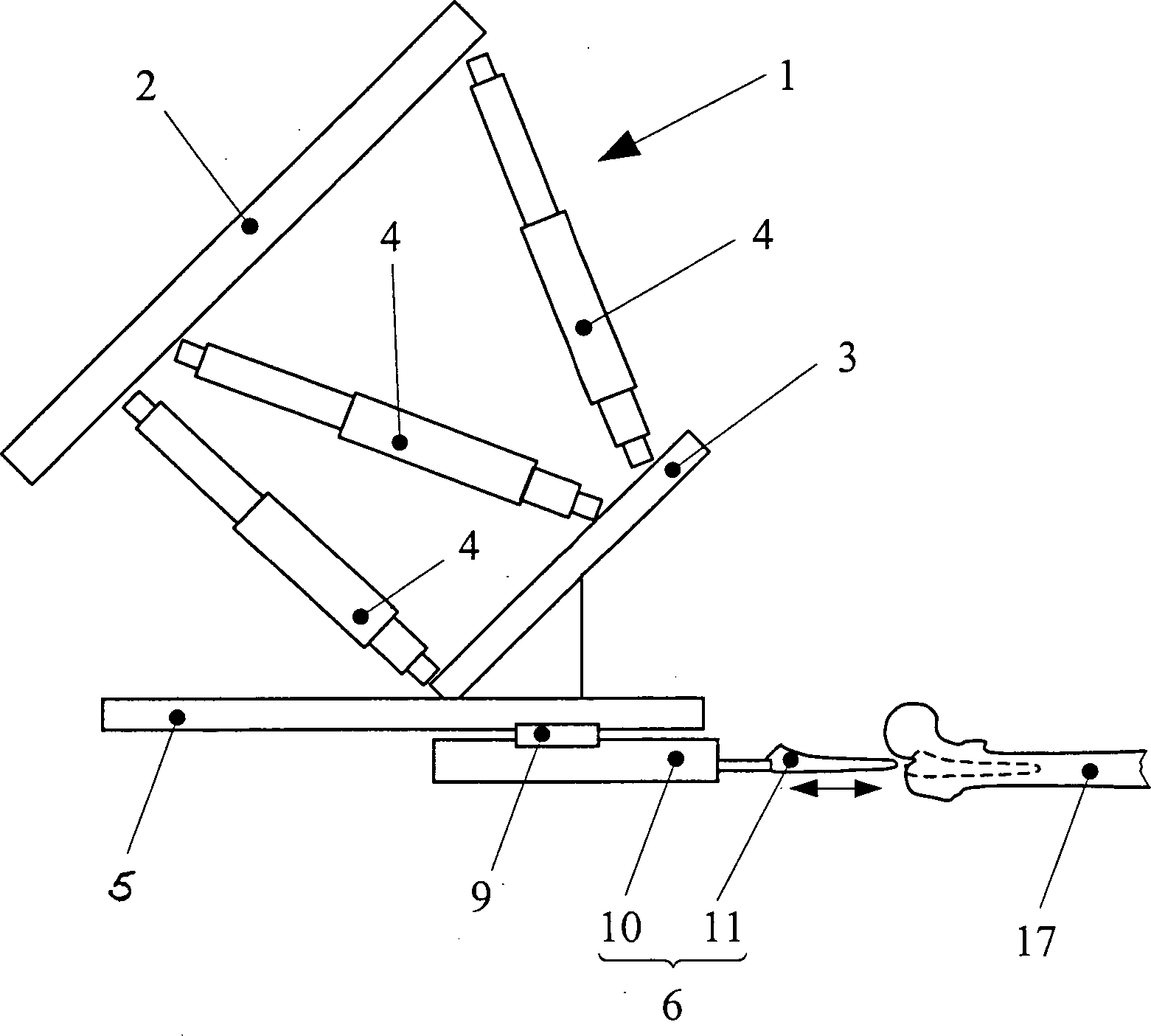
Kernstück der Robotereinheit
ist eine Instrumententrägereinheit
Die
Instrumententrägereinheit
Die
einzelnen Linearantriebe
Diese
Bewegung der Arbeitsplatte
Die
Arbeitsplatte
Mit
der Drehbarkeit und der Schwenkbarkeit der Arbeitsplatte
Das
chirurgische Instrument
Wie
insbesondere die
Das
zerspanende Bearbeitungswerkzeug
Zur
Herstellung einer Kavität
in einem Femur für
die Hüftendoprothetik
wird zunächst
die vorbereitete Position und Lage des Femurs ausgemessen und vom
Rechner des Roboters erfasst und gespeichert. Danach wird die Tiefe
der einzubringenden Kavität
bestimmt und ebenfalls erfasst und gespeichert. Mit diesen Datenspeicherungen
wird anschließend das
chirurgische Instrument
Der
oszillierende Pneumatikantrieb
Mit
der Oszillationsbewegung des Linearantriebes
Diesem
ersten Arbeitsgang folgen in gleicher Weise weitere Arbeitsgänge mit
jeweils größeren Bearbeitungswerkzeugen
Anschließend folgen in bekannter Weise die weiteren erforderlichen Operationshandlungen der Hüftendoprothetik.Then follow in a known manner, the other required operations the hip arthroplasty.
- 11
- InstrumententrägereinheitTool carrier unit
- 22
- Gestellplatteframe plate
- 33
- Arbeitsplattecountertop
- 44
- Linearantrieblinear actuator
- 55
- InstrumentenaufnahmeeinheitInstrument recording unit
- 66
- chirurgisches Instrumentsurgical instrument
- 77
- 88th
- 99
- Instrumentenschlitteninstrument slide
- 1010
- oszillierender Linearantrieboscillating linear actuator
- 1111
- Bearbeitungswerkzeugprocessing tool
- 1212
- SchnellverschlusskupplungQuick Couplings
- 1313
- Handgriffhandle
- 1414
- Bedieneinheitoperating unit
- 1515
- Anschluss für die Druckluftzuführungconnection for the Compressed air supply
- 1616
- Auslassöffnungoutlet
- 1717
- Femurfemur
Claims (5)
Priority Applications (2)
| Application Number | Priority Date | Filing Date | Title |
|---|---|---|---|
| DE10035487A DE10035487B4 (en) | 2000-07-21 | 2000-07-21 | Surgical instrument for working on a bony structure |
| PCT/DE2001/002649 WO2002007631A1 (en) | 2000-07-21 | 2001-07-23 | Surgical instrument for shaping a bony structure |
Applications Claiming Priority (1)
| Application Number | Priority Date | Filing Date | Title |
|---|---|---|---|
| DE10035487A DE10035487B4 (en) | 2000-07-21 | 2000-07-21 | Surgical instrument for working on a bony structure |
Publications (2)
| Publication Number | Publication Date |
|---|---|
| DE10035487A1 DE10035487A1 (en) | 2002-02-07 |
| DE10035487B4 true DE10035487B4 (en) | 2005-01-27 |
Family
ID=7649692
Family Applications (1)
| Application Number | Title | Priority Date | Filing Date |
|---|---|---|---|
| DE10035487A Expired - Fee Related DE10035487B4 (en) | 2000-07-21 | 2000-07-21 | Surgical instrument for working on a bony structure |
Country Status (2)
| Country | Link |
|---|---|
| DE (1) | DE10035487B4 (en) |
| WO (1) | WO2002007631A1 (en) |
Cited By (1)
| Publication number | Priority date | Publication date | Assignee | Title |
|---|---|---|---|---|
| DE102023131771B3 (en) | 2023-09-15 | 2025-02-06 | Esspen Gmbh | Method and device for processing medical image data in connection with a trepanation |
Families Citing this family (3)
| Publication number | Priority date | Publication date | Assignee | Title |
|---|---|---|---|---|
| GB0909281D0 (en) * | 2009-05-29 | 2009-07-15 | Magstim Company The Ltd | Device positioning system |
| WO2011094117A2 (en) | 2010-01-28 | 2011-08-04 | Avery Dennison Corporation | Label applicator belt system |
| CN113288328B (en) * | 2021-06-02 | 2023-02-10 | 上海卓昕医疗科技有限公司 | Osteotomy instrument |
Citations (4)
| Publication number | Priority date | Publication date | Assignee | Title |
|---|---|---|---|---|
| DE3802033C1 (en) * | 1988-01-25 | 1989-06-22 | Hans-Guenter Prof. Dr.-Ing. Appel | Pneumatic striking instrument for medical purposes |
| DE4219939A1 (en) * | 1992-06-18 | 1993-12-23 | Klaus Dipl Ing Radermacher | Template for machining tools for machining bony structures and method for defining and reproducing the positional relationship of a machining tool relative to a bony structure |
| US5299288A (en) * | 1990-05-11 | 1994-03-29 | International Business Machines Corporation | Image-directed robotic system for precise robotic surgery including redundant consistency checking |
| DE4304570A1 (en) * | 1993-02-16 | 1994-08-18 | Mdc Med Diagnostic Computing | Device and method for preparing and supporting surgical procedures |
Family Cites Families (5)
| Publication number | Priority date | Publication date | Assignee | Title |
|---|---|---|---|---|
| US2655921A (en) * | 1951-07-09 | 1953-10-20 | Edward J Haboush | Vibratory tool for operating bone sets, bone chisels, and bone nail drivers |
| US2740406A (en) * | 1954-07-26 | 1956-04-03 | Benjamin F Tofflemire | Pneumatic cutting tool |
| CH681362A5 (en) * | 1990-04-20 | 1993-03-15 | Integral Medizintechnik | |
| DE19820506C1 (en) * | 1998-05-08 | 2000-01-05 | Eska Implants Gmbh & Co | Device for preparing a human long bone for the implantation of a bone implant and method for operating this device |
| EP1079756B1 (en) * | 1998-05-28 | 2004-08-04 | Orthosoft, Inc. | Interactive computer-assisted surgical system |
-
2000
- 2000-07-21 DE DE10035487A patent/DE10035487B4/en not_active Expired - Fee Related
-
2001
- 2001-07-23 WO PCT/DE2001/002649 patent/WO2002007631A1/en not_active Ceased
Patent Citations (4)
| Publication number | Priority date | Publication date | Assignee | Title |
|---|---|---|---|---|
| DE3802033C1 (en) * | 1988-01-25 | 1989-06-22 | Hans-Guenter Prof. Dr.-Ing. Appel | Pneumatic striking instrument for medical purposes |
| US5299288A (en) * | 1990-05-11 | 1994-03-29 | International Business Machines Corporation | Image-directed robotic system for precise robotic surgery including redundant consistency checking |
| DE4219939A1 (en) * | 1992-06-18 | 1993-12-23 | Klaus Dipl Ing Radermacher | Template for machining tools for machining bony structures and method for defining and reproducing the positional relationship of a machining tool relative to a bony structure |
| DE4304570A1 (en) * | 1993-02-16 | 1994-08-18 | Mdc Med Diagnostic Computing | Device and method for preparing and supporting surgical procedures |
Cited By (2)
| Publication number | Priority date | Publication date | Assignee | Title |
|---|---|---|---|---|
| DE102023131771B3 (en) | 2023-09-15 | 2025-02-06 | Esspen Gmbh | Method and device for processing medical image data in connection with a trepanation |
| WO2025056774A1 (en) | 2023-09-15 | 2025-03-20 | Esspen Gmbh | Method and device for processing medical image data in conjunction with a trepanation |
Also Published As
| Publication number | Publication date |
|---|---|
| DE10035487A1 (en) | 2002-02-07 |
| WO2002007631A1 (en) | 2002-01-31 |
Similar Documents
| Publication | Publication Date | Title |
|---|---|---|
| EP1531744B1 (en) | Device for processing parts | |
| EP2027828B1 (en) | Drill guide | |
| DE10309987B4 (en) | Surgical positioning and holding device | |
| DE102010038800B4 (en) | Medical workplace | |
| EP2153793A2 (en) | Manipulation device for a surgical instrument and surgical instrument | |
| WO2017125476A1 (en) | Positioning-device module for releasable connection to a positioning device, positioning device and set | |
| DE4219939A1 (en) | Template for machining tools for machining bony structures and method for defining and reproducing the positional relationship of a machining tool relative to a bony structure | |
| DE3933459A1 (en) | Biomedical implant production equipment - uses computer tomographic image to generate implant profile for component mfr. | |
| EP3082622B1 (en) | Method and system for the controllable adjustment of the material removal rate of hand-guided material-cutting and tissue-cutting tools comprising effectors | |
| WO2008104266A1 (en) | Device for guiding a milling tool on a curved track | |
| EP2303177A1 (en) | Machining device for producing a drilling jig for dental implants | |
| WO2017216073A1 (en) | Patient-positioning device and medical workstation | |
| DE10035487B4 (en) | Surgical instrument for working on a bony structure | |
| DE102006030688A1 (en) | Device for milling recess for holding object, has milling head that is formed for milling bone cavity for receiving joint prosthesis | |
| DE9416957U1 (en) | Device for guiding and fixing surgical instruments | |
| DE10146042A1 (en) | Surgical instrument for shaping a bone structure, e.g. for shaping a hole for prosthesis insertion, has a navigation device with position sensors that ensures the position of a shaping tool relative to the bone is precisely known | |
| EP1663019A1 (en) | Method and device for determining the angle between the femur and the tibia | |
| EP1709929A1 (en) | Worktable for dental technician | |
| DE102006019420B4 (en) | Adjusting tool for replacing a shockwave head of a lithotripsy device mounted on a support arm, shockwave head and method for replacing a shockwave head | |
| DE202013002940U1 (en) | Device for medical and dental purposes | |
| EP1878389B1 (en) | Device for positioning a tool | |
| EP2039305A1 (en) | Processing gauge for producing a resection surface on a joint bone | |
| DE102017127737A1 (en) | Surgical instruments | |
| EP4659689A1 (en) | Resection device | |
| DE102013002815A1 (en) | Device for machining |
Legal Events
| Date | Code | Title | Description |
|---|---|---|---|
| OP8 | Request for examination as to paragraph 44 patent law | ||
| 8339 | Ceased/non-payment of the annual fee |