CN2706921Y - Electric source connector - Google Patents
Electric source connector Download PDFInfo
- Publication number
- CN2706921Y CN2706921Y CNU2004200265470U CN200420026547U CN2706921Y CN 2706921 Y CN2706921 Y CN 2706921Y CN U2004200265470 U CNU2004200265470 U CN U2004200265470U CN 200420026547 U CN200420026547 U CN 200420026547U CN 2706921 Y CN2706921 Y CN 2706921Y
- Authority
- CN
- China
- Prior art keywords
- insulating body
- hole
- power connector
- conductive terminal
- rear end
- Prior art date
- Legal status (The legal status is an assumption and is not a legal conclusion. Google has not performed a legal analysis and makes no representation as to the accuracy of the status listed.)
- Expired - Lifetime
Links
Images


Classifications
-
- H—ELECTRICITY
- H01—ELECTRIC ELEMENTS
- H01R—ELECTRICALLY-CONDUCTIVE CONNECTIONS; STRUCTURAL ASSOCIATIONS OF A PLURALITY OF MUTUALLY-INSULATED ELECTRICAL CONNECTING ELEMENTS; COUPLING DEVICES; CURRENT COLLECTORS
- H01R13/00—Details of coupling devices of the kinds covered by groups H01R12/70 or H01R24/00 - H01R33/00
- H01R13/648—Protective earth or shield arrangements on coupling devices, e.g. anti-static shielding
-
- H—ELECTRICITY
- H01—ELECTRIC ELEMENTS
- H01R—ELECTRICALLY-CONDUCTIVE CONNECTIONS; STRUCTURAL ASSOCIATIONS OF A PLURALITY OF MUTUALLY-INSULATED ELECTRICAL CONNECTING ELEMENTS; COUPLING DEVICES; CURRENT COLLECTORS
- H01R12/00—Structural associations of a plurality of mutually-insulated electrical connecting elements, specially adapted for printed circuits, e.g. printed circuit boards [PCB], flat or ribbon cables, or like generally planar structures, e.g. terminal strips, terminal blocks; Coupling devices specially adapted for printed circuits, flat or ribbon cables, or like generally planar structures; Terminals specially adapted for contact with, or insertion into, printed circuits, flat or ribbon cables, or like generally planar structures
- H01R12/70—Coupling devices
- H01R12/71—Coupling devices for rigid printing circuits or like structures
- H01R12/712—Coupling devices for rigid printing circuits or like structures co-operating with the surface of the printed circuit or with a coupling device exclusively provided on the surface of the printed circuit
- H01R12/716—Coupling device provided on the PCB
Landscapes
- Details Of Connecting Devices For Male And Female Coupling (AREA)
- Coupling Device And Connection With Printed Circuit (AREA)
Abstract
本实用新型公开一种电源连接器,其包括绝缘本体、第一导电端子及第二导电端子。绝缘本体自前端面向后端面延伸形成有收容腔;自所述收容腔后端贯穿绝缘本体的后端面形成有分成前端孔和后端孔两部分的收容孔,前端孔直径大于后端孔直径从而形成一台阶部;第二导电端子为一体式结构,其包括对接部、被阻挡于台阶部前面的固持部及与电路板相接的连接部,连接部设有一弯折部;所述收容孔于绝缘本体的后端面处沿竖直方向向绝缘本体内凹设一凹陷部,其直径等于第二导电端子的连接部的直径,第二导电端子的连接部弯折后收容于其中。这样,绝缘本体上的台阶部及凹陷部的设置有效防止了第二导电端子的前后移动及左右旋转。
The utility model discloses a power supply connector, which comprises an insulating body, a first conductive terminal and a second conductive terminal. The insulating body extends from the front end to the rear end to form a storage cavity; the rear end of the storage cavity runs through the rear end of the insulating body to form a storage hole divided into two parts, the front hole and the rear hole, and the diameter of the front hole is larger than the diameter of the rear hole so that A stepped portion is formed; the second conductive terminal has an integrated structure, which includes a docking portion, a holding portion blocked in front of the stepped portion, and a connecting portion connected to the circuit board, and the connecting portion is provided with a bending portion; the receiving hole A concave portion is recessed vertically into the insulating body at the rear end surface of the insulating body, the diameter of which is equal to the diameter of the connecting portion of the second conductive terminal, and the connecting portion of the second conductive terminal is bent and accommodated therein. In this way, the arrangement of the stepped portion and the recessed portion on the insulating body effectively prevents the second conductive terminal from moving back and forth and rotating left and right.
Description
【技术领域】【Technical field】
本实用新型是有关一种电源连接器,尤其是指一种可良好的固持导电端子的电源连接器。The utility model relates to a power connector, in particular to a power connector which can hold conductive terminals well.
【背景技术】【Background technique】
电源连接器广泛应用于电子领域中,其一般包括分别充当电源的正、负极的中心端子及周围的弹性端子。中心端子及弹性端子均可连接至电路板,从而达成对接电源连接器与电路板之间的电力传输。在与对接电源连接器的完全对接状态下,由于稳定电流传输的需要,必须保证对接电源连接器的端子与中心端子之间具有一定大小的接触力,该接触力的存在会导致在与对接电源连接器的插拔过程中,对接电源连接器的端子与中心端子之间产生一插拔力,而该插拔力势必影响到中心端子在绝缘本体中的固持效果。Power connectors are widely used in the electronic field, and generally include central terminals serving as positive and negative poles of the power supply and surrounding elastic terminals. Both the center terminal and the elastic terminal can be connected to the circuit board, so as to achieve power transmission between the mating power connector and the circuit board. In the fully docked state with the docking power connector, due to the need for stable current transmission, it must be ensured that there is a certain amount of contact force between the terminals of the docking power connector and the center terminal. During the plugging and unplugging process of the connector, a plugging force is generated between the terminal of the docking power connector and the central terminal, and the plugging force will inevitably affect the holding effect of the central terminal in the insulating body.
美国专利公告第6322397号揭示了中心端子依靠设置于其上的一些突起来将中心端子固持于绝缘本体中。当对接电源连接器插入时,所产生的插入力很容易使中心端子向后退出绝缘本体,引起相互接合的不牢靠,影响电流的稳定传输。US Patent Publication No. 6322397 discloses that the center terminal is held in the insulating housing by means of some protrusions disposed thereon. When the docking power connector is inserted, the generated insertion force can easily cause the central terminal to withdraw from the insulating body backward, causing the joint to be unstable and affecting the stable transmission of current.
美国专利第5927999号揭示中心端子与一可连接至电路板的片状端子通过螺帽铆合而将其固定在绝缘本体上,从而阻止了中心端子在对接电源连接器拔出过程中可能发生的向前运动。然而,这种通过片状端子进行电性转接的方式增加了对接电阻,而且元件增多相应产生的问题也多,如片状端子与中心端子之间的铆合松动甚至脱落,从而引起断路。U.S. Patent No. 5,927,999 discloses that the central terminal and a blade terminal that can be connected to the circuit board are fixed on the insulating body by riveting the nut, thereby preventing the central terminal from being pulled out from the docking power connector. forward motion. However, this method of electrical transfer through the blade terminal increases the connection resistance, and the number of components also causes many problems, such as the riveting between the blade terminal and the center terminal becomes loose or even falls off, thereby causing an open circuit.
中国台湾专利公告第558117号揭示了一上顶面具有开口的绝缘本体,中心端子上设置有一环形凹槽,一卡固片从绝缘本体的开口插入而卡入该环形凹槽并将中心端子固持,从而阻制了中心端子在对接电源连接器插拔过程中可能发生的前后运动。然而这种固持方式还是需要额外增加一个元件,而且装配过程复杂,不利于降低生产成本及提高生产效率。China Taiwan Patent Announcement No. 558117 discloses an insulating body with an opening on the top surface, an annular groove is arranged on the center terminal, and a clamping piece is inserted from the opening of the insulating body to snap into the annular groove and hold the center terminal , so as to prevent the center terminal from moving back and forth that may occur in the process of plugging and unplugging the docking power connector. However, this holding method still needs to add an additional component, and the assembly process is complicated, which is not conducive to reducing production costs and improving production efficiency.
所以,需要对上述电源连接器进行改良来克服现有技术的不足。Therefore, it is necessary to improve the above-mentioned power connector to overcome the deficiencies of the prior art.
【实用新型内容】【Content of utility model】
本实用新型的目的在于提供一种电源连接器,其组装构件少,结构简单,导电端子固持牢靠。The purpose of the utility model is to provide a power connector, which has few assembly components, simple structure, and firm holding of conductive terminals.
为实现上述目的,本实用新型采用如下技术方案:一种电源连接器,其包括绝缘本体、第一导电端子及第二导电端子,所述绝缘本体自前端面向后端面延伸形成有用以收容对接连接器的收容腔;自所述收容腔后端贯穿绝缘本体的后端面形成收容孔,该收容孔分成前端孔和后端孔两部分,前端孔直径大于后端孔直径从而形成一台阶部;第二导电端子为一体式结构,其包括突伸入收容腔内的对接部、被阻挡于台阶部前面的固持部及与电路板相接的连接部,该连接部设有一弯折部。In order to achieve the above purpose, the utility model adopts the following technical solutions: a power connector, which includes an insulating body, a first conductive terminal and a second conductive terminal, and the insulating body extends from the front end to the rear end to accommodate the butt connection The storage cavity of the device; the storage hole is formed through the rear end surface of the insulating body from the rear end of the storage cavity, and the storage hole is divided into two parts, the front hole and the rear hole, and the diameter of the front hole is larger than the diameter of the rear hole to form a step; the second The two conductive terminals have an integrated structure, which includes a butt joint protruding into the receiving cavity, a holding portion blocked in front of the stepped portion, and a connection portion connected to the circuit board. The connection portion is provided with a bending portion.
与现有技术相比,本实用新型电源连接器结构简单,且其第二导电端子在绝缘本体中的固持方式牢靠,可有效防止第二导电端子向前、向后的移动及旋转运动,保证电流的稳定传输。Compared with the prior art, the power connector of the utility model has a simple structure, and the holding method of the second conductive terminal in the insulating body is firm, which can effectively prevent the second conductive terminal from moving forward and backward and rotating, ensuring Stable transmission of electric current.
【附图说明】【Description of drawings】
图1为本实用新型电源连接器的前视立体图。FIG. 1 is a front perspective view of the power connector of the present invention.
图2为本实用新型电源连接器的后视立体图。Fig. 2 is a rear perspective view of the power connector of the present invention.
图3为本实用新型电源连接器的前视立体分解图,其中第二导电端子在组装前为直线形,本图显示的是其安装好后的形态。FIG. 3 is a front perspective exploded view of the power connector of the present invention, wherein the second conductive terminal is linear before assembly, and this figure shows its installed form.
图4为本实用新型电源连接器的后视立体分解图,其中第二导电端子在组装前为直线形,本图显示的是其安装好后的形态。Fig. 4 is a rear perspective exploded view of the power connector of the present invention, wherein the second conductive terminal is linear before assembly, and this figure shows its installed form.
图5为沿图1中A-A线的剖视图,但移除了遮蔽壳体及导电端子。FIG. 5 is a cross-sectional view along line A-A in FIG. 1 , but the shielding case and the conductive terminals are removed.
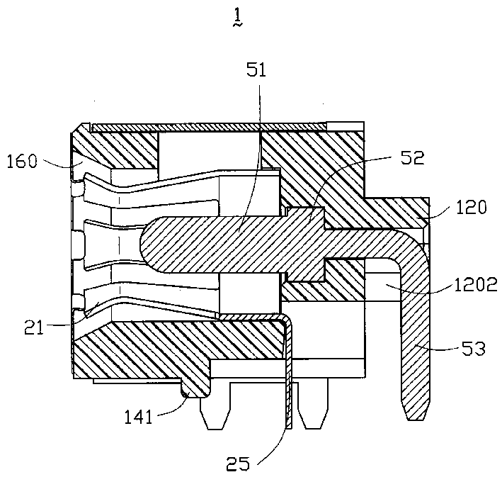
图6为沿图1中A-A线的剖视图,其显示了第二导电端子在绝缘本体中的固持方式。FIG. 6 is a cross-sectional view along line A-A in FIG. 1 , which shows how the second conductive terminal is held in the insulating body.
【具体实施方式】【Detailed ways】
请参阅图1至图4,本实用新型电源连接器1包括有绝缘本体10、第一导电端子20、后遮蔽壳体30、前遮蔽壳体40及第二导电端子50。Referring to FIGS. 1 to 4 , the
请详细参阅图3及图4,绝缘本体10大致成立方体形,其具有一前端面11、后端面12、上顶面13、下底面14及两相互平行的侧面15。自前端面11向后端面12方向凹陷形成有一收容腔,在本实施例中,该收容腔为一圆柱状开孔16,开孔16具有一自前端面11处向后呈渐缩状的导引部160。绝缘本体10的上顶面13中部开设有一与开孔16连通之方形开口130,可在传输电流时起到散热作用。绝缘本体10的后端面12中央凸设出一个凸台120。请再配合参阅图5,自开孔16后端贯穿凸台120形成收容孔,该收容孔分成前端孔17和后端孔18两部分,前端孔17的前端有一导引部170。前端孔17直径为d2,后端孔18直径为d1,d2>d1,从而前端孔17和后端孔18形成一台阶部。前述开孔16、前端孔17及后端孔18皆在同一轴线上。后端孔18在凸台120内还竖直向下贯穿凸台120的底面122,使凸台120下部形成两垂臂1201,两垂臂1201内侧后部各相对凸伸一挡阻块1202,挡阻块1202的前端还设有坡形导面1203,从而在凸台120的后端形成一竖直的凹陷部121。当然也可直接在凸台120后端沿竖直方向向凸台120凹设一凹陷部121。凸台120的正下方还开设了一矩形槽道124,其向前延伸一定距离并与开孔16贯通。后端面12的左右两侧中部分别开设一方孔125,其亦与开孔16相通。Please refer to FIG. 3 and FIG. 4 in detail. The
请再参阅图3及图4,绝缘本体10的下底面14的前端和左右两侧面分别设有棱条140,起垫高作用。而下底面14中部还垂直设有一导引柱141,在将电源连接器1安装至电路板(未图示)上时起导引作用。绝缘本体10的左右两侧面15上分别对称设有凸块150。从整体上看,绝缘本体10的上顶面13和左右侧面15与前端面11相接处分别设有同样宽度的凸棱101,与后端面12相接的角上也分别设有相同宽度的突起102。Please refer to FIG. 3 and FIG. 4 again. Ribs 140 are respectively provided on the front end and the left and right sides of the lower bottom surface 14 of the
请再参阅图3所示,在本实施例中,第一导电端子20为六瓣型的环状配置,其头部21呈喇叭状,喇叭型头部21的末端即为第一导电端子20的接合部22。而其尾部23仍然连接在一起成一环形。在第一导电端子20尾部23的左右两侧各向后延伸出固持部24,而尾部23的正下方也向后延伸出接触部25。在组装至绝缘本体10时,请参阅图1、图2及图6所示,第一导电端子20的喇叭状头部21贴合至绝缘本体10的开孔16的导引部160上,第一导电端子20的固持部24及接触部25分别伸入绝缘本体10后端面12上的矩形槽道123及方孔124中,并分别将它们进行左右和垂直向下的弯折,这样,固持部24的末端贴合后端面12并与后端面12及左右两侧面15齐平,从而将第一导电端子20固持至绝缘本体10上。而接触部25的末端凸伸出绝缘本体10的下底面14而与电路板(未图示)连接。Please refer to FIG. 3 again. In this embodiment, the first
为防止第二导电端子50通过片状端子转接连接至电路板而可能引起的因二者连接不紧密甚至脱落而使电流传输发生断路,本实用新型电源连接器的第二导电端子50采用一体式结构。请参阅图3所示,第二导电端子50包括一与对接电源连接器(未图示)接合的对接部51、固持部52及一与电路板(未图示)相接的连接部53,三者位于一条直线上。在本实施例中,对接部51、固持部52及连接部53皆呈圆柱形,其中固持部52的直径大小大致与前述前端孔17的直径d2相等,连接部53的直径大小大致与前述后端孔18的直径d1相等,d2>d1。请结合参阅图2、图3、图5及图6所示,第二导电端子50从绝缘本体10的前端面11组入开孔16中,连接部53紧贴的穿过前端孔17及后端孔18而延伸出绝缘本体10外,而固持部52由于其直径d2大于前述后端孔18的直径d1,无法通过后端孔18,从而被阻挡在后端孔18前方,即前述的台阶部。因此,在对接电源连接器(未图示)插入的过程中,该台阶部可以阻止第二导电端子50受接插力的作用而沿插接方向后退。第二导电端子50的连接部53延伸出绝缘本体10后,在连接部53刚伸出绝缘本体10的那个部位用治具对它进行弯折,使其弯折部位正好卡在凸台120的凹陷部121的挡阻块1202之后。这样,当对接电源连接器(未图示)拔出时,挡阻块1202阻挡住第二导电端子50的弯折段连接部53,防止其随着对接电源连接器(未图示)向前窜动。而两个垂壁1201的卡合又可防止第二导电端子50在收容孔内的左右旋转。In order to prevent the second
请再参阅图1至图4所示,本电源连接器还设有两遮蔽壳体,前遮蔽壳体40遮覆于绝缘本体10的前端面11,其中央开设一与绝缘本体10的开孔16同轴且同径的孔41,孔41边缘向内设有若干弹片42。前遮蔽壳体40的左右两侧设有两翼部43,翼部43对应于绝缘本体10两侧面15上的凸棱101处设置有扣口44,两者相配合从而使前遮蔽壳体40固持于绝缘本体10上。Please refer to Figures 1 to 4 again, the power connector is also provided with two shielding shells, the
后遮蔽壳体30呈“U”型,其两侧壁31上对应于绝缘本体10两侧壁15的凸块150处设置有凹口32,从而在组装时相互扣合而将后遮蔽壳体30固持于绝缘本体10上。后遮蔽壳体30各壁面的宽度亦恰好等于绝缘本体10各侧面上的突起102与前遮蔽壳体40两翼部43末端所夹的距离,从而使后遮蔽壳体30各壁面恰好嵌入其中,从而也起到一定的固持作用。后遮蔽壳体30两侧壁31的底端还垂直延伸有定位片33,用于将其定位至电路板上。The
当然,本实用新型的实施方式不限于以上描述。如第二导电端子50可以是六边形的,还可以取消凸台120,而直接在后端孔18于绝缘本体10的后端面12处沿竖直方向向绝缘本体10内凹设一凹陷部121而收容第二导电端子50的连接部53的弯折部位。Of course, the embodiments of the present invention are not limited to the above description. For example, the second
Claims (9)
Priority Applications (2)
| Application Number | Priority Date | Filing Date | Title |
|---|---|---|---|
| CNU2004200265470U CN2706921Y (en) | 2004-04-20 | 2004-04-20 | Electric source connector |
| US11/026,636 US7108514B2 (en) | 2004-04-20 | 2004-12-30 | Power connector |
Applications Claiming Priority (1)
| Application Number | Priority Date | Filing Date | Title |
|---|---|---|---|
| CNU2004200265470U CN2706921Y (en) | 2004-04-20 | 2004-04-20 | Electric source connector |
Publications (1)
| Publication Number | Publication Date |
|---|---|
| CN2706921Y true CN2706921Y (en) | 2005-06-29 |
Family
ID=34849477
Family Applications (1)
| Application Number | Title | Priority Date | Filing Date |
|---|---|---|---|
| CNU2004200265470U Expired - Lifetime CN2706921Y (en) | 2004-04-20 | 2004-04-20 | Electric source connector |
Country Status (2)
| Country | Link |
|---|---|
| US (1) | US7108514B2 (en) |
| CN (1) | CN2706921Y (en) |
Cited By (3)
| Publication number | Priority date | Publication date | Assignee | Title |
|---|---|---|---|---|
| CN102468554A (en) * | 2010-11-04 | 2012-05-23 | 安费诺硕民科技(深圳)有限公司 | Audio connector |
| CN102823068A (en) * | 2010-06-07 | 2012-12-12 | 菲尼克斯电气有限两合公司 | Cable connection system and method of connecting cables to the cable connection system |
| CN109066154A (en) * | 2018-08-15 | 2018-12-21 | 四川永贵科技有限公司 | A kind of curved formula connecting terminal of heavy-current electric connector |
Families Citing this family (41)
| Publication number | Priority date | Publication date | Assignee | Title |
|---|---|---|---|---|
| US7278863B1 (en) * | 2006-04-26 | 2007-10-09 | Cheng Uei Precision Industry Co., Ltd. | Receptacle connector |
| US7462078B2 (en) * | 2007-04-26 | 2008-12-09 | Cheng Uei Precision Industry Co., Ltd. | Power connectors |
| US7387532B1 (en) | 2007-04-30 | 2008-06-17 | Cheng Uei Precision Industry Co., Ltd. | Power connector |
| US20090137133A1 (en) * | 2007-11-26 | 2009-05-28 | Pony Gou | F-type right angle jack |
| TW201012010A (en) * | 2008-09-15 | 2010-03-16 | Wistron Neweb Corp | Female adapter for a connector |
| TWM378534U (en) * | 2009-03-31 | 2010-04-11 | Hon Hai Prec Ind Co Ltd | Electrical connector and electrical connector assembly |
| US9833098B2 (en) | 2009-07-14 | 2017-12-05 | Loominocity, Inc. | Architecture for routing multi-channel commands via a tree column |
| US10993572B2 (en) | 2009-07-14 | 2021-05-04 | Belgravia Wood Limited | Power pole for artificial tree apparatus with axial electrical connectors |
| US11096511B2 (en) | 2009-07-14 | 2021-08-24 | Belgravia Wood Limited | Power pole for artificial tree apparatus with axial electrical connectors |
| US7934960B1 (en) * | 2009-12-19 | 2011-05-03 | Cheng Uei Precision Industry Co., Ltd. | Power jack connector |
| TWI412186B (en) * | 2009-12-25 | 2013-10-11 | Hon Hai Prec Ind Co Ltd | Electrical connector and electrical connector assembly |
| US8916242B2 (en) | 2009-12-31 | 2014-12-23 | Polygroup Macau Limited (Bvi) | Connector system |
| JP5756608B2 (en) * | 2010-07-15 | 2015-07-29 | 矢崎総業株式会社 | connector |
| TWM399523U (en) * | 2010-09-06 | 2011-03-01 | Jye Tai Prec Ind Co Ltd | Improved high power socket connector |
| US8454186B2 (en) | 2010-09-23 | 2013-06-04 | Willis Electric Co., Ltd. | Modular lighted tree with trunk electical connectors |
| JP5373757B2 (en) * | 2010-12-22 | 2013-12-18 | 日本航空電子工業株式会社 | connector |
| US8298633B1 (en) | 2011-05-20 | 2012-10-30 | Willis Electric Co., Ltd. | Multi-positional, locking artificial tree trunk |
| CN202183474U (en) * | 2011-07-01 | 2012-04-04 | 富士康(昆山)电脑接插件有限公司 | Electric connector |
| US8342860B1 (en) * | 2011-09-20 | 2013-01-01 | The United States Of America As Represented By The Secretary Of The Navy | Interface board connector |
| US8863416B2 (en) | 2011-10-28 | 2014-10-21 | Polygroup Macau Limited (Bvi) | Powered tree construction |
| US8569960B2 (en) | 2011-11-14 | 2013-10-29 | Willis Electric Co., Ltd | Conformal power adapter for lighted artificial tree |
| US9157587B2 (en) | 2011-11-14 | 2015-10-13 | Willis Electric Co., Ltd. | Conformal power adapter for lighted artificial tree |
| US8876321B2 (en) | 2011-12-09 | 2014-11-04 | Willis Electric Co., Ltd. | Modular lighted artificial tree |
| US8574013B2 (en) * | 2012-04-10 | 2013-11-05 | Cheng Uei Precision Industry Co., Ltd. | Power plug having solering tails of a contact terminal and a sleeve terminal projecting outside a body |
| US8568175B1 (en) * | 2012-04-10 | 2013-10-29 | Cheng Uei Precision Industry Co., Ltd. | Power plug having a terminal with soldering arms clamping a soldering tail of another terminal |
| US9044056B2 (en) | 2012-05-08 | 2015-06-02 | Willis Electric Co., Ltd. | Modular tree with electrical connector |
| US9179793B2 (en) | 2012-05-08 | 2015-11-10 | Willis Electric Co., Ltd. | Modular tree with rotation-lock electrical connectors |
| US9572446B2 (en) | 2012-05-08 | 2017-02-21 | Willis Electric Co., Ltd. | Modular tree with locking trunk and locking electrical connectors |
| US10206530B2 (en) | 2012-05-08 | 2019-02-19 | Willis Electric Co., Ltd. | Modular tree with locking trunk |
| TWM453262U (en) * | 2012-10-12 | 2013-05-11 | Hon Hai Prec Ind Co Ltd | Electrical connector |
| US9671074B2 (en) | 2013-03-13 | 2017-06-06 | Willis Electric Co., Ltd. | Modular tree with trunk connectors |
| US9439528B2 (en) | 2013-03-13 | 2016-09-13 | Willis Electric Co., Ltd. | Modular tree with locking trunk and locking electrical connectors |
| US9894949B1 (en) | 2013-11-27 | 2018-02-20 | Willis Electric Co., Ltd. | Lighted artificial tree with improved electrical connections |
| US8870404B1 (en) | 2013-12-03 | 2014-10-28 | Willis Electric Co., Ltd. | Dual-voltage lighted artificial tree |
| US9883566B1 (en) | 2014-05-01 | 2018-01-30 | Willis Electric Co., Ltd. | Control of modular lighted artificial trees |
| US9839315B2 (en) | 2015-03-27 | 2017-12-12 | Polygroup Macau Limited (Bvi) | Multi-wire quick assemble tree |
| US9907136B2 (en) | 2016-03-04 | 2018-02-27 | Polygroup Macau Limited (Bv) | Variable multi-color LED light string and controller for an artificial tree |
| DE102016217673B4 (en) * | 2016-09-15 | 2020-06-04 | Te Connectivity Germany Gmbh | Electrical contact for a connector, with rotatable rolling contact bodies and electrical plug connection with such a contact |
| US10122130B2 (en) * | 2016-09-22 | 2018-11-06 | Te Connectivity Corporation | Connector assembly with an insulator |
| US10441014B1 (en) | 2017-01-03 | 2019-10-15 | Willis Electric Co., Ltd. | Artificial tree having multiple tree portions with electrical connectors secured therein |
| US10683974B1 (en) | 2017-12-11 | 2020-06-16 | Willis Electric Co., Ltd. | Decorative lighting control |
Family Cites Families (5)
| Publication number | Priority date | Publication date | Assignee | Title |
|---|---|---|---|---|
| US4360244A (en) * | 1980-05-12 | 1982-11-23 | Amp Incorporated | Miniature coaxial connector assembly |
| US5062811A (en) * | 1990-10-30 | 1991-11-05 | Amp Incorporated | Capacitive coupled connector for PCB grounding |
| JP3262018B2 (en) | 1997-04-16 | 2002-03-04 | ホシデン株式会社 | Power jack |
| TW449135U (en) | 2000-05-16 | 2001-08-01 | Hon Hai Prec Ind Co Ltd | Electrical connector |
| US6932614B1 (en) * | 2004-04-13 | 2005-08-23 | Shin-Nan Kan | Socket with double functions |
-
2004
- 2004-04-20 CN CNU2004200265470U patent/CN2706921Y/en not_active Expired - Lifetime
- 2004-12-30 US US11/026,636 patent/US7108514B2/en not_active Expired - Lifetime
Cited By (4)
| Publication number | Priority date | Publication date | Assignee | Title |
|---|---|---|---|---|
| CN102823068A (en) * | 2010-06-07 | 2012-12-12 | 菲尼克斯电气有限两合公司 | Cable connection system and method of connecting cables to the cable connection system |
| CN102823068B (en) * | 2010-06-07 | 2016-01-13 | 菲尼克斯电气有限两合公司 | Cable connection system and method of connecting cables to the cable connection system |
| CN102468554A (en) * | 2010-11-04 | 2012-05-23 | 安费诺硕民科技(深圳)有限公司 | Audio connector |
| CN109066154A (en) * | 2018-08-15 | 2018-12-21 | 四川永贵科技有限公司 | A kind of curved formula connecting terminal of heavy-current electric connector |
Also Published As
| Publication number | Publication date |
|---|---|
| US20050233603A1 (en) | 2005-10-20 |
| US7108514B2 (en) | 2006-09-19 |
Similar Documents
| Publication | Publication Date | Title |
|---|---|---|
| CN2706921Y (en) | Electric source connector | |
| US10205256B2 (en) | Plug and electrical connector component | |
| CN2735591Y (en) | Cable connector assembly | |
| CN2674704Y (en) | Cable connector assembly | |
| CN201252244Y (en) | Electrical connector component | |
| CN101212090B (en) | Electric connector | |
| CN2891352Y (en) | High Density Electrical Connector | |
| CN201204275Y (en) | electrical connector | |
| CN2737005Y (en) | Electric connector | |
| CN2850038Y (en) | Electric connector assembly | |
| CN201285976Y (en) | Electric connector component | |
| CN200959434Y (en) | electrical connector | |
| CN201160133Y (en) | electrical connector | |
| CN2770136Y (en) | Cable connector assembly | |
| CN2513240Y (en) | Electric connector | |
| CN200972953Y (en) | Electric connector | |
| CN201303109Y (en) | Electric connector | |
| CN2809973Y (en) | Power supply connector | |
| CN2682659Y (en) | Cable connector assembly | |
| CN102044779A (en) | Electrical connector | |
| CN201096919Y (en) | Electric connector | |
| CN213816537U (en) | Electrical connector assembly | |
| CN2757377Y (en) | Electric connector | |
| CN2737012Y (en) | Electronic commutator | |
| CN2682662Y (en) | Electric connector |
Legal Events
| Date | Code | Title | Description |
|---|---|---|---|
| C14 | Grant of patent or utility model | ||
| GR01 | Patent grant | ||
| C17 | Cessation of patent right | ||
| CX01 | Expiry of patent term |
Expiration termination date: 20140420 Granted publication date: 20050629 |