CN218726031U - But building appraisal apparatus of split combination - Google Patents
But building appraisal apparatus of split combination Download PDFInfo
- Publication number
- CN218726031U CN218726031U CN202221132928.1U CN202221132928U CN218726031U CN 218726031 U CN218726031 U CN 218726031U CN 202221132928 U CN202221132928 U CN 202221132928U CN 218726031 U CN218726031 U CN 218726031U
- Authority
- CN
- China
- Prior art keywords
- identification
- appraisal
- cylinder
- fixed
- fixed cylinder
- Prior art date
- Legal status (The legal status is an assumption and is not a legal conclusion. Google has not performed a legal analysis and makes no representation as to the accuracy of the status listed.)
- Expired - Fee Related
Links
Images


Landscapes
- A Measuring Device Byusing Mechanical Method (AREA)
Abstract
Description
技术领域technical field
本实用新型涉及一种照明装置,具体地说是一种可拆分组合的建筑鉴定用具。The utility model relates to a lighting device, in particular to a detachable and combined building identification tool.
背景技术Background technique
抗压检测用具是建筑行业验收的主要鉴定工具之一,主要通过冲压鉴定建筑材料、施工面等是否符合施工要求。但目前的该种鉴定用具鉴定的范围比较窄,而且对比例也较少,难以从多方面对建筑施工面等进行更全面地鉴定。Compression testing tools are one of the main identification tools for acceptance in the construction industry, mainly through stamping to identify whether building materials and construction surfaces meet the construction requirements. However, the scope of identification of the current identification tools is relatively narrow, and the comparison ratio is relatively small, so it is difficult to conduct a more comprehensive identification of the construction surface from various aspects.
实用新型内容Utility model content
为解决上述问题,本实用新型的目的是提供一种可拆分组合的建筑鉴定用具,具有多种可组合的形态,从而可以更多样化地对建筑材料、施工面等进行抗压鉴定。In order to solve the above problems, the purpose of this utility model is to provide a detachable and combined building identification tool, which has a variety of combinable forms, so that the compression resistance of building materials and construction surfaces can be more diversified.
本实用新型为实现上述目的,一种可拆分组合的建筑鉴定用具,包括固定筒和固定在固定筒一端的按压把手,固定筒内设置有多个内鉴定筒,各内鉴定筒内分别通过弹簧弹性固定有鉴定头固定块,鉴定头固定块的另一端固定有可拆卸的鉴定头,且鉴定头分别分为平面结构接触头、锥形结构接触头以及尖形结构接触头,且固定筒最下端的内鉴定筒伸出固定筒外,最下端的内鉴定筒通过贯穿其自身以及固定筒侧壁的螺栓螺母固定连接,最下端的内鉴定筒两侧分别设置有支撑测试腿,支撑测试腿的上部分分别与固定筒的侧壁固定连接,且常态下弹簧使鉴定头延伸长度超过支撑测试腿的下端。In order to achieve the above purpose, the utility model provides a detachable and combined building identification tool, which includes a fixed cylinder and a pressing handle fixed at one end of the fixed cylinder. A plurality of internal identification cylinders are arranged in the fixed cylinder, and each internal identification cylinder passes through the The spring elastically fixes the identification head fixing block, and the other end of the identification head fixing block is fixed with a detachable identification head, and the identification head is divided into a flat structure contact head, a conical structure contact head and a pointed structure contact head, and the fixed cylinder The lowermost inner identification cylinder protrudes out of the fixed cylinder, and the lowermost inner identification cylinder is fixedly connected by bolts and nuts that run through itself and the side wall of the fixed cylinder. The two sides of the lowermost inner identification cylinder are respectively provided with supporting test legs to support the test. The upper parts of the legs are respectively fixedly connected with the side walls of the fixed cylinder, and under normal conditions, the spring makes the extension length of the identification head exceed the lower end of the supporting test legs.
进一步地,每个内鉴定筒内的弹簧规格不同,使每条弹簧发生相同形变量时而弹力不同。Furthermore, the specifications of the springs in each inner identification cylinder are different, so that when each spring undergoes the same deformation, the elastic force is different.
进一步地,鉴定头通过螺纹结构与鉴定头固定块固定连接。Further, the identification head is fixedly connected with the identification head fixing block through a threaded structure.
进一步地,支撑测试腿的下端分别固定有支撑平板。Further, the lower ends of the supporting test legs are respectively fixed with supporting plates.
进一步地,按压把手左右对称设置,且每个按压把手上套有橡胶防滑套。Further, the pressing handles are symmetrically arranged left and right, and each pressing handle is covered with a rubber anti-slip sleeve.
由于采用以上技术方案,本实用新型具有多种可组合的检测形态,使检测对比性更多,更好地满足鉴定需求,同时也能从多方面充分保证检测的准确性。Due to the adoption of the above technical solutions, the utility model has a variety of combinable detection forms, which makes the detection more contrastive, better meets the needs of identification, and can fully guarantee the accuracy of detection from various aspects.
附图说明Description of drawings
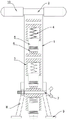
图1是本实用新型的主视结构示意图;Fig. 1 is the front view structural representation of the utility model;
图2-4是本实用新型的使用状态参考图。Fig. 2-4 is the reference diagram of the use status of the utility model.
具体实施方式Detailed ways
下面将结合附图对本实用新型的技术方案进行清楚、完整地描述,显然,所描述的实施例是本实用新型一部分实施例,而不是全部的实施例。基于本实用新型中的实施例,本领域普通技术人员在没有做出创造性劳动前提下所获得的所有其他实施例,都属于本实用新型保护的范围。在本实用新型的描述中,需要说明的是,术语“中心”、“上”、“下”、“左”、“右”、“竖直”、“水平”、“内”、“外”等指示的方位或位置关系为基于附图所示的方位或位置关系,仅是为了便于描述本实用新型和简化描述,而不是指示或暗示所指的装置或元件必须具有特定的方位、以特定的方位构造和操作,因此不能理解为对本实用新型的限制。The technical solutions of the utility model will be clearly and completely described below in conjunction with the accompanying drawings. Apparently, the described embodiments are part of the embodiments of the utility model, but not all of them. Based on the embodiments of the present utility model, all other embodiments obtained by persons of ordinary skill in the art without making creative efforts belong to the scope of protection of the present utility model. In the description of the present utility model, it should be noted that the terms "center", "upper", "lower", "left", "right", "vertical", "horizontal", "inner", "outer" The orientation or positional relationship indicated by etc. is based on the orientation or positional relationship shown in the drawings, which is only for the convenience of describing the utility model and simplifying the description, rather than indicating or implying that the device or element referred to must have a specific orientation, use a specific The azimuth structure and operation, therefore can not be construed as the limitation of the present utility model.
在本实用新型的描述中,需要说明的是,除非另有明确的规定和限定,术语“安装”、“相连”、“连接”应做广义理解,例如,可以是固定连接,也可以是可拆卸连接,或一体地连接;可以是机械连接,也可以是电连接;可以是直接相连,也可以通过中间媒介间接相连,可以是两个元件内部的连通。对于本领域的普通技术人员而言,可以具体情况理解上述术语在本实用新型中的具体含义。In the description of the present utility model, it should be noted that, unless otherwise clearly stipulated and limited, the terms "installation", "connection" and "connection" should be understood in a broad sense, for example, it can be a fixed connection or a flexible connection. Detachable connection, or integral connection; it can be mechanical connection or electrical connection; it can be direct connection or indirect connection through an intermediary, and it can be the internal communication of two components. Those of ordinary skill in the art can understand the specific meanings of the above terms in the present utility model in specific situations.
下面结合附图对本实施例进行详细描述:The present embodiment is described in detail below in conjunction with accompanying drawing:
本实施例提供了一种可拆分组合的建筑鉴定用具,请一并参照说明书附图中图1-4。This embodiment provides a detachable and combined building identification tool, please refer to Figures 1-4 in the accompanying drawings.
如图1-4所示,一种可拆分组合的建筑鉴定用具,包括固定筒1和固定在固定筒1一端的按压把手2,固定筒1内设置有多个内鉴定筒3,各内鉴定筒3内分别通过弹簧4弹性固定有鉴定头固定块5,且每个内鉴定筒3内的弹簧4规格不同,使每条弹簧4发生相同形变量时而弹力不同,鉴定头固定块5的另一端固定有可拆卸的鉴定头6,如鉴定头6通过螺纹结构与鉴定头固定块5固定连接,便于拆卸及更换,且鉴定头6分别分为平面结构接触头、锥形结构接触头以及尖形结构接触头,且固定筒1最下端的内鉴定筒3伸出固定筒1外,最下端的内鉴定筒3通过贯穿其自身以及固定筒1侧壁的螺栓螺母7固定连接,最下端的内鉴定筒3两侧分别设置有支撑测试腿8,支撑测试腿8的上部分分别与固定筒1的侧壁固定连接,且常态下弹簧4使鉴定头6延伸长度超过支撑测试腿8的下端。As shown in Figures 1-4, a detachable and combined building identification tool includes a fixed cylinder 1 and a
为了提高支撑测试腿8与待测部位等接触面积,支撑测试腿8的下端分别固定有支撑平板9。In order to increase the contact area between the
为了便于手持,按压把手2左右对称设置,且每个按压把手2上套有橡胶防滑套10。For the convenience of holding, the
本实用新型工作原理:鉴定测试时,使鉴定头6与待检测建筑材料、施工面等接触,然后按压至支撑测试腿8与待检测建筑材料、施工面接触,这样每次按压到位后,再不更换内鉴定筒3、弹簧4的情况下,弹簧4作用于鉴定头6的弹力不变,因此对建筑材料、施工面等压力不变;如图2、3使用,弹簧4的规格不变,相同压缩状态下弹力不变,改变了鉴定头6与待检测面的接触面积,即改变了压强,即保持弹簧4弹力情况下,进行压强检测;如图2、4,则相当于更换了弹簧4的规格,即相同压缩状态下改变了弹簧4的弹力,而此时鉴定头6与待检测面的接触面积不变,即在保证接触面积不变的情况下进行压力测试。另外还有其他多种检测方式,使检测对比性更多,充分保证检测的准确性。The working principle of the utility model: during the identification test, the
当然,上述说明并非是对本实用新型的限制,本实用新型也并不限于上述举例,本技术领域的普通技术人员,在本实用新型的实质范围内,作出的变化、改变、添加或替换,都应属于本实用新型的保护范围。Of course, the above description is not a limitation of the present utility model, and the present utility model is not limited to the above-mentioned examples. Those of ordinary skill in the art can make changes, changes, additions or replacements within the essential scope of the present utility model. Should belong to the protection scope of the present utility model.
Claims (5)
Priority Applications (1)
| Application Number | Priority Date | Filing Date | Title |
|---|---|---|---|
| CN202221132928.1U CN218726031U (en) | 2022-05-12 | 2022-05-12 | But building appraisal apparatus of split combination |
Applications Claiming Priority (1)
| Application Number | Priority Date | Filing Date | Title |
|---|---|---|---|
| CN202221132928.1U CN218726031U (en) | 2022-05-12 | 2022-05-12 | But building appraisal apparatus of split combination |
Publications (1)
| Publication Number | Publication Date |
|---|---|
| CN218726031U true CN218726031U (en) | 2023-03-24 |
Family
ID=85580584
Family Applications (1)
| Application Number | Title | Priority Date | Filing Date |
|---|---|---|---|
| CN202221132928.1U Expired - Fee Related CN218726031U (en) | 2022-05-12 | 2022-05-12 | But building appraisal apparatus of split combination |
Country Status (1)
| Country | Link |
|---|---|
| CN (1) | CN218726031U (en) |
-
2022
- 2022-05-12 CN CN202221132928.1U patent/CN218726031U/en not_active Expired - Fee Related
Similar Documents
| Publication | Publication Date | Title |
|---|---|---|
| CN102778389B (en) | Concrete test loading device and test method under load and multifactor coupling | |
| CN218726031U (en) | But building appraisal apparatus of split combination | |
| CN202452928U (en) | Thickness detecting jig | |
| CN205246825U (en) | Efficient circuit board detection device | |
| CN205449646U (en) | Spring extensometer cantilever bar positioner and spring extensometer | |
| CN207215471U (en) | Automobile connection plate inspection tool | |
| CN203745189U (en) | Crank centering device used for crankshaft fatigue test | |
| CN207351332U (en) | Frame right longitudinal beam inner reinforcement plate inspection tool | |
| CN207656558U (en) | Sheet metal component hole positioning fixture | |
| CN212460074U (en) | Mechanical type direction detection mechanism | |
| CN209840923U (en) | Surface detection pin device | |
| CN208366211U (en) | It is a kind of for detecting the cubing of the hole location of Automobile heat shield | |
| CN206643809U (en) | A kind of cubing pair alignment pin | |
| CN221945758U (en) | Enameled wire verifying attachment | |
| CN205066639U (en) | Lower roller hitching leg verifying attachment | |
| CN207197926U (en) | A kind of rubber type of material tensile test fixture | |
| CN216954337U (en) | Test gauge | |
| CN110686762B (en) | Portable Electric Ground Balance Quick Verification Device | |
| CN217953311U (en) | Crankshaft lightening hole position measuring instrument | |
| CN217180476U (en) | Vicat instrument | |
| CN223107369U (en) | A threaded steel bar convenient for measuring bending | |
| CN218036040U (en) | Stainless steel resistance to compression detects workstation | |
| CN218155896U (en) | Sheet metal part thickness precision measurement device | |
| CN103471483B (en) | Pxe piston automatic measuring instrument | |
| CN217818426U (en) | Go-no go gauge convenient to change screw gauge head |
Legal Events
| Date | Code | Title | Description |
|---|---|---|---|
| GR01 | Patent grant | ||
| GR01 | Patent grant | ||
| CF01 | Termination of patent right due to non-payment of annual fee |
Granted publication date: 20230324 |
|
| CF01 | Termination of patent right due to non-payment of annual fee |