CN217584104U - LED lighting equipment - Google Patents
LED lighting equipment Download PDFInfo
- Publication number
- CN217584104U CN217584104U CN202220182213.0U CN202220182213U CN217584104U CN 217584104 U CN217584104 U CN 217584104U CN 202220182213 U CN202220182213 U CN 202220182213U CN 217584104 U CN217584104 U CN 217584104U
- Authority
- CN
- China
- Prior art keywords
- led lighting
- lighting device
- light
- unit
- light source
- Prior art date
- Legal status (The legal status is an assumption and is not a legal conclusion. Google has not performed a legal analysis and makes no representation as to the accuracy of the status listed.)
- Active
Links
Images


Landscapes
- Arrangement Of Elements, Cooling, Sealing, Or The Like Of Lighting Devices (AREA)
- Non-Portable Lighting Devices Or Systems Thereof (AREA)
Abstract
The utility model provides a LED lighting apparatus, a serial communication port, include: a lamp cap; a light emitting unit; the light-emitting unit is electrically connected with the power supply; the heat exchange unit comprises fins, and the light emitting unit is fixed on the heat exchange unit; the second convection channel dissipates heat to the fins in a convection mode; the light emitting unit comprises a first light source and a second light source, when the lamp cap is installed along the vertical direction, the first light source at least provides lateral light emission, and the second light source and the first light source are configured to emit light towards different directions.
Description
Technical Field
The utility model belongs to the technical field of LED lighting device, specifically speaking relates to a LED lighting apparatus.
Background
LED lighting is widely used because of its advantages such as energy saving and long life. The LED lighting devices in the prior art commonly include a flat lamp and a grille lamp.
The prior art LED lighting device (such as an LED corn lamp) includes a heat sink, a lamp housing, a light source, a power source, and a lamp head. The lamp shell is connected with the lamp cap, the power supply is arranged in the lamp shell, the radiator is connected with the lamp shell, and the light source is fixed on the radiator. Such LED lighting devices in the prior art have the following disadvantages: the lamp housing occupies the length space of the whole lamp, so that the luminous area of the whole lamp occupies less area in the length direction, and the light emitting effect is influenced; corn lights typically use fans to dissipate heat, which are costly and may affect the life of the entire light
In summary, in view of the deficiencies and defects of the LED lighting device in the prior art, how to design the LED lighting device to solve the problems of heat dissipation and light emission is a technical problem to be solved by those skilled in the art.
SUMMERY OF THE UTILITY MODEL
This abstract describes many embodiments of the invention. The term "invention" is used merely to describe some of the embodiments disclosed in this specification (whether or not in the claims), and not a complete description of all possible embodiments. Certain embodiments described above as various features or aspects of the invention can be combined in different ways to form an LED lighting device or a portion thereof.
An embodiment of the utility model provides a new LED lighting apparatus to and the characteristic of each aspect, in order to solve above-mentioned problem.
An embodiment of the utility model provides a 1, LED lighting apparatus, a serial communication port, include:
a lamp cap;
a light emitting unit;
the light-emitting unit is electrically connected with the power supply;
the heat exchange unit comprises fins, and the light emitting unit is fixed on the heat exchange unit; and
the second convection channel dissipates heat to the fins in a convection mode;
the light emitting unit comprises a first light source and a second light source, when the lamp cap is installed along the vertical direction, the first light source at least provides lateral light emission, and the second light source and the first light source are configured to emit light towards different directions.
The embodiment of the utility model provides a work as when the lamp holder was installed along vertical direction, the second light source provides decurrent light-emitting.
The embodiment of the utility model provides a the fin has a plurality of groups, the fin is followed LED lighting apparatus's axial direction extends the setting, and a plurality of the fin is in LED lighting apparatus's radial inboard forms an accommodation space, at least some configurations of power in the accommodation space.
The embodiment of the utility model provides an at least 80% on the power length direction is located in the accommodation space.
The embodiment of the utility model provides a power dispose completely in the accommodation space.
The embodiment of the utility model provides a still include the isolation unit, the isolation unit includes the isolation tube, the isolation tube is fixed in the accommodation space, the power is fixed in the isolation tube.
The embodiment of the utility model provides a form first convection current way in the isolation tube, it is right in the isolation tube the power dispels the heat.
The embodiment of the utility model provides a length of first convection current way accounts for more than 50%, 55%, 60%, 65% or 70% of the total length of LED lighting apparatus in the axial direction of LED lighting apparatus.
The embodiment of the utility model provides a length of second convection current channel on the axial direction of LED lighting apparatus accounts for more than 50%, 55%, 60%, 65% or 70% of the total length of LED lighting apparatus.
The embodiment of the utility model provides an inside heat conduction material that fills of isolation tube is with the cladding the power.
The embodiment of the utility model provides a power includes electronic component and circuit board, electronic component is fixed in on the circuit board, electronic component includes heating element, heating element exposes in at least 85% of outside surface area and adheres to the heat conduction material.
The embodiment of the utility model provides a power includes electronic component and circuit board, electronic component is fixed in on the circuit board, electronic component includes heating element, arbitrary one heating element exposes in at least 85%, 90% or 95% of outside surface area and attaches to the heat conduction material.
The embodiment of the utility model provides a power includes electronic component and circuit board, electronic component is fixed in on the circuit board, the length of circuit board accounts for more than 60% of heat exchange unit's length, just the circuit board is located completely in the space that heat exchange unit injectd.
The embodiment of the utility model provides a length of circuit board accounts for more than 70% of heat exchange unit's length.
The embodiment of the utility model provides a length of circuit board accounts for more than 80% of heat exchange unit's length.
The embodiment of the utility model provides a still include optical unit, luminous unit includes the first lamp plate of a plurality of groups, first light source set up in on the first lamp plate, optical unit includes first optics component, and is a set of first optics component corresponds one or two first light source.
An embodiment of the present invention provides that the area configuration of the outer surface of the first optical member occupies at least 15% or more of the area of the surface of the radial outer side of the LED lighting device.
The embodiment of the utility model provides a light-emitting unit includes the second lamp plate, the second light source is fixed on the second lamp plate, the second lamp plate laminate in the heat exchange unit is kept away from the terminal surface of the one end of lamp holder, optical unit includes second optics component, second optics component cover is located outside the second light source.
The embodiment of the utility model provides a heat exchange unit includes the base, the base has outside surface and mounting surface, mounting surface is located the outside surface in more inboard of LED lighting apparatus's radial direction, just light-emitting unit install in behind the mounting surface, its position is in do not surpass in LED lighting apparatus's the radial direction the position on outside surface.
The embodiment of the utility model provides an outside surface is shared the central angle on the surface in the radial outside of LED lighting apparatus is less than the surface of first optical member is shared the central angle on the surface in the radial outside of LED lighting apparatus.
The embodiment of the present invention provides that when the light of the first light source is projected to the first optical member within the range of the beam angle a thereof, at least 60% or more of the width of the inner surface of the first optical member in the width direction has the light from the direct irradiation within the range of the beam angle a of the first light source.
The embodiment of the utility model provides a still include the electric connection unit, the electric connection unit includes the electric connection board, the circuit layer has been arranged on the electric connection board, the electric connection board configure into at least with more than two sets of first lamp plate realizes connecting, and the electric connection board with the power electricity is connected.
The embodiment of the utility model provides a be provided with a plurality of fixed orificess on the electric connection board, first lamp plate passes the fixed orifices, and with the electric connection board is connected.
The embodiment of the utility model provides a fin is including being located the inside first portion of base and revealing in the outside second portion of base, the ratio of the length of second portion with the length of fin is 1.
The embodiment of the utility model provides a heat exchange unit includes the base, the spacer tube has first portion and second portion in its axial, first portion with the second portion is followed LED lighting apparatus length direction has equal length, the weight setting of the heat conduction material in the first portion is greater than the weight of the heat conduction material in the second portion.
The heat exchange unit of the embodiment of the utility model provides a base, the spacer tube has first portion and second portion in its axial, first portion with the second portion is followed LED lighting apparatus length direction has equal length, the quantity of electronic component in the first portion is more than the quantity of electronic component in the second portion.
In an embodiment of the present invention, at least a portion of the first portion corresponds to fins exposed outside the base.
An embodiment of the utility model provides a still provide a LED lighting apparatus, a serial communication port, include:
a lamp cap;
a light emitting unit;
the light-emitting unit is electrically connected with the power supply;
the heat exchange unit comprises fins, and the light emitting unit is fixed on the heat exchange unit;
a first convection channel that convectively dissipates heat from the power supply; and
the second convection channel dissipates heat to the fins in a convection mode;
the light emitting unit comprises a first light source which provides at least lateral light emission when the lamp head is mounted in a vertical direction;
the length of the first convection channel and/or the second convection channel in the axial direction of the LED lighting device accounts for more than 50%, 55%, 60%, 65%, or 70% of the total length of the LED lighting device.
The embodiment of the utility model provides a light-emitting unit still includes the second light source, the second light source with first light source configuration is towards different direction light-emitting.
The embodiment of the utility model provides a work as when the lamp holder was installed along vertical direction, the second light source provides decurrent light-emitting.
The embodiment of the utility model provides a the fin has a plurality of groups, the fin is followed LED lighting apparatus's axial direction extends the setting, and is a plurality of the fin is in LED lighting apparatus's radial inboard forms an accommodation space, at least some configurations of power in the accommodation space, at least 80% on the power length direction are located in the accommodation space.
The embodiment of the utility model provides a still include the isolation unit, the isolation unit includes the isolation tube, the isolation tube is fixed in the accommodation space, the power is fixed in the isolation tube, form in the isolation tube first convection current way, it is right in the isolation tube the power dispels the heat.
The embodiment of the utility model provides a power includes electronic component and circuit board, electronic component is fixed in on the circuit board, the length of circuit board accounts for more than 60% of heat exchange unit's length, just the circuit board is located completely in the space that heat exchange unit injectd.
The embodiment of the utility model provides a still include optical unit, luminous unit includes the first lamp plate of a plurality of groups, first light source set up in on the first lamp plate, optical unit includes first optics component, and is a set of first optics component corresponds one or two first light source.
The embodiment of the utility model provides a luminous unit includes the second lamp plate, the second light source is fixed on the second lamp plate, the second lamp plate laminate in the heat exchange unit is kept away from the terminal surface of the one end of lamp holder, optical unit includes second optics component, second optics component cover is located outside the second light source.
The embodiment of the utility model provides a heat exchange unit includes the base, the base has outside surface and mounting surface, mounting surface is located outside surface in more inboard of LED lighting apparatus's radial direction, just light-emitting unit install in behind the mounting surface, its position is in do not surpass in LED lighting apparatus's the radial direction the position on outside surface.
The embodiment of the utility model provides an outside surface is shared the central angle on the surface in the radial outside of LED lighting apparatus is less than the surface of first optical member is shared the central angle on the surface in the radial outside of LED lighting apparatus.
The embodiment of the present invention provides that when the light of the first light source is projected to the first optical member within the range of the beam angle a thereof, at least 60% or more of the width of the inner surface of the first optical member in the width direction has the light from the direct irradiation within the range of the beam angle a of the first light source.
The embodiment of the utility model provides a still include electric connecting element, electric connecting element includes the electric connection board, the circuit layer has been arranged on the electric connection board, the electric connection board configuration be at least with more than two sets of first lamp plate realizes connecting, and the electric connection board with the power electricity is connected.
The embodiment of the utility model provides a be provided with a plurality of fixed orificess on the electricity link plate, first lamp plate passes the fixed orifices, and with the electricity link plate is connected.
The embodiment of the utility model provides a fin is including being located the inside first portion of base and revealing in the outside second portion of base, the ratio of the length of second portion with the length of fin is 1.
Compared with the prior art, the utility model outstanding and profitable technological effect is: when the lamp cap is installed along the vertical direction, the first light source can emit light to the side direction of the LED lighting equipment, and the second light source can emit light to the lower part of the LED lighting equipment, so that the LED lighting equipment can emit light more uniformly, and a dark zone is prevented from being formed below the LED lighting equipment; the LED lighting equipment is provided with the first convection channel for radiating the power supply in the isolation tube, so that the radiating efficiency can be improved, and the weight of the whole lamp can be reduced; the LED lighting equipment is provided with the second convection channel to dissipate heat of the fins, so that the heat dissipation efficiency can be improved; the length of the first convection channel and/or the second convection channel in the axial direction of the LED lighting device accounts for more than 50%, 55%, 60%, 65% or 70% of the total length of the LED lighting device, and the first convection channel and/or the second convection channel can be ensured to have enough length to meet the chimney effect in convection; the length of the circuit board of the power supply accounts for more than 60% of the length of the heat exchange unit, so that the circuit board has more sizes for arranging the electronic elements, and the heating elements in the electronic elements can be arranged at larger intervals.
Drawings
Fig. 1 is a schematic front view of an LED lighting device according to an embodiment of the present invention;
FIG. 2 is a schematic top view of FIG. 1;
FIG. 3 is a schematic bottom view of FIG. 1;
fig. 4 is a schematic cross-sectional view of an LED lighting device according to an embodiment of the present invention;
FIG. 5 is an enlarged view at A in FIG. 4;
fig. 6 is a first schematic perspective view of an LED lighting device according to an embodiment of the present invention;
fig. 7 is a second schematic perspective view of an LED lighting device according to an embodiment of the present invention;
fig. 8 is a schematic perspective view of the LED lighting device according to the embodiment of the present invention, with the cover and the dust screen removed;
fig. 9 is an enlarged view at B in fig. 8;
FIG. 10 is a schematic perspective view of an isolation tube;
FIG. 11 is a front view of the cover;
FIG. 12 is a schematic front view of a dust screen;
FIG. 13 is a schematic perspective view of an LED lighting device in one embodiment;
FIG. 14 is a cross-sectional structural schematic of FIG. 13;
fig. 15 is an enlarged view at C in fig. 14;
FIG. 16 is a schematic view of the second optical member of FIG. 13 with the second optical member removed;
FIG. 17 is a schematic view of the light panel and the second light source removed from FIG. 16;
FIG. 18 is a diagram showing an intensity distribution of a longitudinal section (a section along an axial direction of the LED lighting apparatus) of the LED lighting apparatus in one embodiment;
FIG. 19 is a perspective view of the optical member and the first cover of FIG. 13 with the second optical member removed;
FIG. 20 is a schematic perspective view of the alternative orientation of FIG. 19;
fig. 21 is an enlarged view at D in fig. 19;
fig. 22 is a schematic perspective view of an LED lighting device in some embodiments;
fig. 23 is a schematic sectional structure view of the LED lighting device in fig. 22;
FIG. 24 is an enlarged view at E in FIG. 23;
FIG. 25 is a first schematic perspective view of an LED lighting device in one embodiment;
FIG. 26 is a second schematic perspective view of an LED lighting apparatus in an embodiment;
FIG. 27 is a schematic cross-sectional view of an LED lighting apparatus in one embodiment;
FIG. 28 is an enlarged view at F of FIG. 27;
FIG. 29 is a first schematic perspective view of the LED lighting device of FIG. 25 with the optical unit removed;
fig. 30 is an enlarged view at G in fig. 29;
fig. 31 is a second perspective view of the LED lighting device of fig. 25 with the optical unit removed.
Fig. 32 is a schematic perspective view of an LED lighting device in an embodiment.
Fig. 33 is a schematic perspective view of a second LED lighting device in an embodiment.
Fig. 34 is an enlarged schematic view at J in fig. 33.
Fig. 35 is a schematic front view of an LED lighting device in an embodiment.
Fig. 36 is a schematic sectional structure view of an LED lighting device in an embodiment.
Fig. 37 is an enlarged schematic view at H in fig. 36.
Fig. 38 is a schematic perspective view of the LED lighting device with the second optical member removed in one embodiment.
Fig. 39 is an enlarged schematic view at I in fig. 38.
Fig. 40 is a schematic perspective view of a heat exchange unit of an LED lighting device in an embodiment.
Fig. 41 is a schematic perspective view of an isolation tube of an LED lighting device in an embodiment.
Fig. 42 is a schematic sectional structure view of an LED lighting device in an embodiment.
Detailed Description
Embodiments of the present invention will now be described more fully hereinafter with reference to the accompanying drawings, in which embodiments of the invention are shown. The present invention may, however, be embodied in many different forms and should not be construed as limited to the embodiments set forth herein. Rather, these embodiments are provided so that this disclosure will be thorough and complete, and will fully convey the scope of the invention to those skilled in the art. Like reference symbols in the various drawings indicate like elements.
It will be understood that, although the terms first, second, etc. may be used herein to describe various elements, these elements should not be limited by these terms. These terms are only used to distinguish one element from another element. For example, a first element could be termed a second element, and, similarly, a second element could be termed a first element, without departing from the scope of the present invention. As used herein, the term "and/or" includes any and all combinations of one or more of the associated listed items.
It will be understood that when an element such as a layer, region or substrate is referred to as being "on" or extending "onto" another element, it can be directly on or extend directly onto the other element or intervening elements may also be present. In contrast, when an element is referred to as being "directly on" or extending "directly onto" another element, there are no intervening elements present. It will also be understood that when an element is referred to as being "connected" or "coupled" to another element, it can be directly connected or coupled to the other element or intervening elements may be present. In contrast, when an element is referred to as being "directly connected" or "directly coupled" to another element, there are no intervening elements present.
Relative terms, such as "below" or "above" or "upper" or "lower" or "horizontal" or "vertical" may be used herein to describe one element, layer or region's relationship to another element, layer or region as illustrated in the figures. It will be understood that these terms are intended to encompass different orientations of the device in addition to the orientation depicted in the figures. In the present invention, the "vertical", "horizontal" and "parallel" are defined as: including ± 10% of cases based on the standard definition. For example, vertical generally refers to an angle of 90 degrees relative to a reference line, but in the present invention, vertical refers to a situation that includes within 80 to 100 degrees.
The terminology used herein is for the purpose of describing particular embodiments only and is not intended to be limiting of the invention. As used herein, the singular forms "a", "an" and "the" are intended to include the plural forms as well, unless the context clearly indicates otherwise. It will be further understood that the terms "comprises," "comprising," "includes" and/or "including," when used herein, specify the presence of stated features, integers, steps, operations, elements, and/or components, but do not preclude the presence or addition of one or more other features, integers, steps, operations, elements, components, and/or groups thereof.
Unless otherwise defined, all terms (including technical and scientific terms) used herein have the same meaning as commonly understood by one of ordinary skill in the art to which this invention belongs. It will be further understood that terms used herein should be interpreted as having a meaning that is consistent with their meaning in the context of this specification and the relevant art and will not be interpreted in an idealized or overly formal sense unless expressly so defined herein.
Unless expressly stated otherwise, comparative quantitative terms such as "less than" and "greater than" are intended to encompass the equivalent concept. By way of example, "less than" may mean not only "less than" in the strictest mathematical sense, but also "less than or equal to".
As shown in fig. 1 to 5, an embodiment of the present invention provides an LED lighting device (without a fan). The LED lighting apparatus includes: lamp holder 1, light emitting unit 2, power supply 3 and heat exchange unit 4. Wherein the lamp cap 1 is configured for connection to an external power supply unit, such as a lamp holder. The heat exchange unit 4 is directly or indirectly connected to the lamp cap 1. The light-emitting unit 2 is electrically connected to the power supply 3, the light-emitting unit 2 is fixed on the heat exchange unit 4, a heat conduction path is formed between the light-emitting unit 2 and the heat exchange unit 4, and at least part of heat generated by the light-emitting unit 2 during operation is dissipated through the heat exchange unit 4.
In this embodiment, the heat exchange unit 4 includes a base 41, and the light emitting unit 2 is disposed on a surface of the base 41. Specifically, the cross-sectional shape of the base 41 is configured as a generally annular or tubular structure having an outer side surface 411. In one embodiment, the outer surface 411 of the base 41 constitutes the radially outermost side of the LED lighting device. The base 41 is further provided with a mounting surface 412, and the light emitting unit 2 is disposed on the mounting surface 412. The mounting surface 412 is located further inside the outer side surface 411 in the radial direction of the LED lighting device, and after the light emitting unit 2 is mounted on the mounting surface 412, the position of the mounting surface is not beyond the position of the outer side surface 411 in the radial direction of the LED lighting device, so that the outer side surface 412 can protect the light emitting unit 2 to a certain extent, and the light emitting unit 2 is prevented from being damaged due to collision.
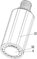
In this embodiment, the light emitting unit 2 includes a first lamp panel 21 and a first light source 22, and the first light source 22 is disposed on the first lamp panel 21. The first light source 22 in this embodiment may be an LED lamp bead or other type of light emitting device in the prior art. First lamp plate 21 is laminated on mounting surface 412 of base 41 to be favorable to first lamp plate 21 quick conduct the heat to heat exchange unit 4. Specifically, in some embodiments, the first lamp panel 21 is riveted to the heat exchanging unit 4. In some embodiments, the first lamp panel 21 is connected to the heat exchange unit by bolts. In some embodiments, the first lamp panel 21 is fixed to the heat exchange unit 4 by welding. In some embodiments, the first lamp panel 21 is adhered to the heat exchanging unit 4, and the adhesive is selected from a material with a high thermal conductivity. As shown in fig. 5, in some embodiments, a fixing unit (slot) is disposed on the base 41 for fixing the first lamp panel 21, specifically, the first lamp panel 21 is inserted into the slot (i.e. the fixing unit) for cooperation. First lamp plate 21 in this embodiment is provided with a plurality of groups, and a plurality of groups of first lamp plates 21 are arranged along the circumference of heat exchange unit 4. That is, the outer side of the heat exchange unit 4 has several sets of mounting surfaces 412 in the circumferential direction for mounting a corresponding number of sets of first lamp panels 21. In this embodiment, the first light source 22 provides at least lateral light emission when the lamp head 1 is mounted in the vertical direction.
The LED lighting device in the present embodiment may further include an optical unit 5, and the optical unit 5 is configured to have one or more functions of light transmission, light diffusion, transmittance increase, or light condensation. In addition, the optical unit 5 can also be used to provide physical protection for the light-emitting unit 2, so as to prevent the light-emitting unit 2 from being damaged by external force.
The optical unit 5 includes a first optical member 51, the first optical member 51 covers the first light source 22, and light generated by the first light source 22 during operation passes through the first optical member 51 and is emitted from the LED lighting device. In this embodiment, the mounting surface 412 forms a mounting groove 413 due to the difference in position from the outer surface 411. In one embodiment, at least a portion of the first optical member 51 is received in the mounting groove 413. In one embodiment, the first optical member 51 is completely received in the mounting groove 413, that is, the first optical member 51 does not exceed the range defined by the outer side surface 411 in the radial direction of the LED lighting device. In addition, the outer surface of the first optical member 51 is substantially smoothly transitioned with the outer side surface 411 to make the heat exchange unit 4 of the LED lighting device more integral in appearance. Specifically, the radius of curvature of the outer surface of the first optical member 51 is substantially or completely the same as the radius of curvature of the outer side surface 411. In the present embodiment, the outer side surface 411 and the outer surface of the first optical member 51 together constitute a surface on the outer side in the radial direction of the LED lighting device. Wherein the base 41 has a thermal conductivity greater than that of the first optical member 51. And the area of the surface of the outer side 411 occupying the outer side in the radial direction of the LED illumination apparatus is larger than the area of the surface of the outer surface of the first optical member 51 occupying the outer side in the radial direction of the LED illumination apparatus, so that the surface of the outer side in the radial direction of the LED illumination apparatus has more efficient heat dissipation efficiency. Further, the area of the outer side surface 411 may occupy 65% or more of the area of the surface on the outer side in the radial direction of the LED lighting device. In addition, the outer surface of the first optical member 51 is configured to transmit light generated by the light emitting unit 2 during operation, and in order to visually improve the light emitting effect of the surface on the outer side in the radial direction of the LED lighting device, the area of the outer surface of the first optical member 51 is configured to occupy at least 15% or more of the area of the surface on the outer side in the radial direction of the LED lighting device, so as to improve the light emitting area in the lateral direction of the LED lighting device, that is, the area of the outer surface 411 occupies no more than 85% of the area of the surface on the outer side in the radial direction of the LED lighting device.
In another embodiment, in order to generate better light processing effect, the first optical member 51 is beyond the range (not shown) defined by the outer side surface 411 in the radial direction of the LED lighting device, i.e. the outer surface of the first optical member 51 and the outer side surface 411 are in a staggered pattern. Specifically, the radius of curvature of the outer surface of the first optical member 51 is smaller than the radius of curvature of the outer side surface 411, and the outer side surface 411 and the outer surface of the first optical member 51 together constitute a radially outer surface of the LED lighting device.
The mounting groove 413 forms a slot 414 (i.e., a fixing unit for fixing the first optical member 51) at an edge of the mounting surface 412, and a side of the first optical member 51 has a flange 511, and the flange 511 is disposed in the slot 414. When mounted, the first optical member 51 is inserted into the insertion groove 414 in the axial direction of the heat exchange unit 4. In some embodiments, the first optical member 51 may be further fixed, such as by providing a rivet, bolt, glue, snap, etc. to fix the first optical member 51 to the heat exchange unit 4.
The first optical member 51 in the present embodiment has a light diffusion function. In one embodiment, the first optical member 51 is provided with a diffusion coating on its surface to provide it with light diffusion function. In one embodiment, the first optical member 51 has a light diffusion function due to its material property, such as a plastic material with a light diffusion function in the prior art.
As shown in fig. 22 to 24, in some embodiments, in order to improve the light extraction effect of the side surface of the lamp, the central angle occupied by the surface of the outer side surface 411 in the radial direction of the LED lighting device may be smaller than the central angle occupied by the surface of the outer surface of the first optical member 51 in the radial direction of the LED lighting device, so that the surface of the outer side of the LED lighting device in the radial direction has a larger light extraction area, and the light extraction effect is improved. That is, on the side portion of the LED lighting device, the area of the light emitting portion thereof (the portion where the first optical member 51 is exposed to the outside of the LED lighting device, or is not shielded) is larger than the area of the non-light emitting portion (the outer side surface 411). However, in order to ensure the heat dissipation from the outer surface 411 to the outside, it is necessary to ensure that the ratio of the central angle (or area) occupied by the surface of the outer surface 411 on the outer side in the radial direction of the LED lighting device to the central angle (or area) occupied by the surface of the outer surface of the first optical member 51 on the outer side in the radial direction of the LED lighting device is not less than 1. Because the central angle occupied by the outer surface 411 is reduced, the heat dissipation performance may be reduced, and for this reason, a plurality of heat dissipation bars 4111 may be disposed on the outer surface 411 to increase the surface area thereof, so as to improve the heat dissipation efficiency (have a larger surface area for external radiation), and in addition, the disposition of the heat dissipation bars 411 may also play a role of anti-skid. The heat radiation bars 4111 may be arranged along the axial extension of the heat exchange unit 4.
As shown in fig. 22 to 24, a space is provided between adjacent heat dissipation bars 4111, and a ratio of a dimension of the space to a dimension of a thickness of the heat dissipation bars 4111 is greater than 0.8. The height dimension of the heat radiation bars 4111 is set not to exceed the thickness dimension of the heat radiation bars 4111 (or the height dimension of the heat radiation bars 4111 is set to be equal to or less than the thickness dimension of the heat radiation bars 4111) to prevent the adjacent heat radiation bars 4111 from affecting each other to the heat radiated from the outside (the heat radiation bars 4111 radiate the heat to the adjacent heat radiation bars 4111).
As shown in fig. 22 to 24, an inner side surface of the base 41 opposite to the outer side surface 411 may also be provided with a heat radiation bar 4111. That is, the heat dissipation bars 4111 may be disposed on an outer side surface and/or an inner side surface of the outer side surface 411.
As shown in fig. 22 to 24, since the central angle occupied by the surface of the outer surface of the first optical member 51 occupying the outer side of the LED lighting device in the radial direction is increased, the first light sources 22 on the first lamp panel 21 may be arranged in two rows, and the two rows of the first light sources 22 are distributed along the circumferential direction of the lamp. The number of the fins 42 of the heat exchange unit 4 may be set to be the same as that of the first lamp panel 21, and the fins 42 are disposed in one-to-one correspondence with the first lamp panel 21 (the extending direction of the fins 42 corresponds to the middle area of the back of the lamp panel 21), so that the heat conduction path may be reduced. In order to improve the heat dissipation efficiency of the fins 42, a plurality of heat dissipation fins 421 may be further disposed on the surface of the fins 42 to increase the overall heat dissipation area of the fins 42. The first light source 22 may include two or more groups of LED beads of different types (e.g., color temperature, luminous flux, size, etc.) to provide a basis for color and light modulation of the LED lighting device.
As shown in fig. 23, the light emitting surface of the first light source 22 and the inner surface of the first optical member 51 are spaced apart by a distance, which is at least greater than 2mm, for example. The first light source 22 has a beam angle a (the beam angle of the LED lamp bead is defined as the angle formed by the two sides where the light intensity reaches 50% of the normal light intensity), and in fig. 23, when the light of the first light source 22 is projected to the first optical member 51 within the beam angle a, at least 60% or more of the width of the inner surface of the first optical member 51 in the width direction has direct light from the first light source 22 within the beam angle a. That is, the beam angle a of the first light source 22, projected to the first optical member 51, covers at least 60% in the width direction of the first optical member 51. With the above arrangement, the light emitted from the first light source 22 can be projected onto the first optical member 51 as uniformly as possible, thereby preventing the light beam angle from corresponding to only a local area of the first optical member 51 and causing local strong light, and thus causing poor visual effects, such as enhanced visual graininess, on the surface of the first optical member 51. As shown in fig. 23, the beam angles a of the two sets of first light sources 22 at least partially overlap after being projected onto the first optical member 51. In other embodiments, the above-mentioned criteria can be met when a group of the first optical members 51 corresponds to only one row of the first light sources 22, so as to reduce the visual impact, such as graininess, of the first optical members 51.
As shown in fig. 13 to 17 and 19 to 21, in an embodiment, the LED lighting device may further include an electrical connection unit, and the electrical connection unit is used for electrically connecting the plurality of groups of first lamp panels 21. The electrical connection unit includes an electrical connection board 201, a circuit layer is arranged on the electrical connection board 201, and the electrical connection board 201 is configured to be connected (structurally connected and/or electrically connected) with at least two sets or more of the first lamp panels 21. And the electrical connection board 201 is electrically connected to the power source 3. Therefore, the connection between the plurality of groups of first lamp panels 21 and the power supply 3 can be simplified. In one embodiment, the plurality of groups of first lamp panels 21 are connected to the electrical connection board 201.
As shown in fig. 19 to 21, in an embodiment, the electrical connection board 201 is configured in a ring shape, and a circuit layer is disposed on the electrical connection board 201. At least one end of the fins 42 in the length direction of the heat exchange unit 4 in the present embodiment exceeds the base 41, that is, a part of the fins 42 is exposed out of the base 41 in the length direction of the heat exchange unit 4. The electrical connection plate 201 is disposed on the portion of the fin 42 exposed outside the base 41. At this time, the electrical connection board 201 corresponds to one end of the first optical member 22, and forms a limit to the one end of the first optical member 22.
A plurality of fixing holes 2011 are arranged on the electrical connection board 201 in this embodiment, and the first lamp panel 21 passes through the fixing holes 2011 and is connected with the electrical connection board 201. For example, after the first lamp panel 21 passes through the fixing hole 2011, it is directly fixed to the electrical connection board 201 by welding. For another example, the first lamp panel 21 is connected to the electrical connection board 201 through a wire after passing through the fixing hole 2011. In this embodiment, the first lamp panel 21 has a first portion attached to the base 41 and a second portion exposed outside the base 41, and the second portion is disposed in the fixing hole 2011, so that the second portion can be fixed through the fixing hole 2011, and the movement of the second portion of the first lamp panel 21 in the radial direction of the LED lighting device is limited. In addition, the electrical connection board 201 is a PCB (printed circuit board), and the first lamp panel 21 is an aluminum substrate, and the thermal expansion coefficients of the electrical connection board 201 and the first lamp panel 21 are different. Because the second part of first lamp plate 21 is not fixed in on base 41, consequently, when electric connection board 201 is heated the thermal expansion, can be with the synchronous activity of the second part of first lamp plate 21, prevent that the electric connection point between the two from breaking.
The LED lighting device may further include a first cover 202, and the first cover 202 covers the electrical connection board 201 to prevent the electrical connection board 201 and the first lamp panel 21 from being directly exposed. In this embodiment, the first cover 202 is disposed at one end of the first lamp panel 21 and/or the first optical member 22.
The LED lighting device may further include a second cover 203, wherein the second cover 203 is fixed on the heat exchanging unit 4 and located at the other end of the first lamp panel 21 opposite to the electrical connection board 201. The second cover 203 is disposed at the other end of the first lamp panel 21 and/or the first optical member 22 opposite to the first cover 202. Thus, the first cover 202 and the first cover 203 can define the position of the first lamp panel 21 and/or the first optical member 22.
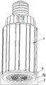
As shown in fig. 1 to 5, 8 and 9, the light emitting unit 2 may further include a second lamp panel 23 and a second light source 24, and the second light source 24 is fixed on the second lamp panel 23. The second light source 24 in this embodiment may be an LED lamp bead in the prior art. The second lamp plate 23 is attached to the end face of the end, away from the lamp holder 1, of the heat exchange unit 4, so that heat can be conducted to the heat exchange unit 4 rapidly through the second lamp plate 23. Specifically, in some embodiments, the second lamp panel 23 is riveted to the heat exchange unit 4. In some embodiments, the second lamp panel 23 is connected to the heat exchange unit by bolts. In some embodiments, the second lamp panel 23 is fixed to the heat exchange unit 4 by welding. In some embodiments, the second lamp panel 23 and the heat exchange unit 4 are adhered and fixed by an adhesive with high thermal conductivity. The second lamp panel 23 in this embodiment is provided with 1 or more groups. After second light source 24 located second lamp plate 23, second light source 24 roughly is cyclic annular distribution. In this embodiment, the second light source 24 provides downward light emission when the light head 1 is mounted vertically. The first light source 22 and the second light source 24 are arranged to emit light in different directions.
The optical unit 5 may further include a second optical member 52, and the second optical member 52 is disposed to cover the second light source 24. The second optical member 52 in the present embodiment has a light diffusion function. In one embodiment, the second optical member 52 is provided with a diffusion coating on its surface to provide light diffusion function. In one embodiment, the second optical member 52 has a light diffusion function by its own material property, such as a plastic material with a light diffusion function in the prior art.
As shown in fig. 13 to 17, in an embodiment, the second lamp panel 23 is disposed in a middle area of the end surface of the heat exchanging unit 4, and the second lamp panel 23 is only connected to the fins 42 directly or indirectly. That is, in the projection direction of the axial direction of the heat exchange unit 4, the second lamp panel 23 only overlaps the fins 42, and does not overlap the base 41. To solve the problem of heat dissipation of the second lamp panel 23, the LED lighting device in this embodiment may further include a heat conducting portion 204 for rapidly conducting the heat conducted to the second lamp panel 23 by the second light source 24 to the fins 42. In this embodiment, when the fin 42 projects to the second lamp panel 23 along the axial direction of the LED lighting device, the area of the second lamp panel 23 is smaller than the contact area between the heat conducting portion 204 and the fin 42. In this embodiment, if the end surface of the fin 42 directly contacts the second lamp panel 23, the heat exchange area may be insufficient, and the heat dissipation requirement cannot be met. The heat conducting portion 201 in this embodiment is cup-shaped and is fixed to the fin 42 by bolts. The second lamp panel 23 can be attached to the heat conducting portion 204, and can be connected to the heat conducting portion by means of bolts, glue, or fasteners. Meanwhile, the second optical member 52 covers the second lamp panel 23, and only the second lamp panel 23 is covered completely. Further, the second optical member 52 covers the heat conduction portion 204 to prevent the heat conduction portion 204 from being exposed and to prevent the external portion from directly contacting the heat conduction portion 204.
In order to improve the uniformity of the light distribution of the LED lighting device, the light intensity value of the lateral light-emitting direction of the LED lighting device and the light intensity value of the downward light-emitting direction need to be balanced in this embodiment. For example, in the light intensity distribution in the longitudinal sectional direction of the LED illumination apparatus, the ratio of the light intensity value of any beam angle of downward light emission to the light intensity value of any beam angle of lateral light emission is set to 1: 0.6-1.5. Further, setting the ratio of the light intensity value of any beam angle of downward light outgoing to the light intensity value of any beam angle of lateral light outgoing to be 1: 0.8-1.5. Furthermore, the ratio of the light intensity value of any beam angle for emitting light downwards to the light intensity value of any beam angle for emitting light laterally is set as 1:1 to 1.4. In this embodiment, the light intensity value of any beam angle for emitting light downwards refers to the light intensity value in the light emitting range of-40 to-40 in fig. 18, and the light intensity value of any beam angle for emitting light sideways refers to the light intensity value in the light emitting range of-40 to-100 and 40 to 100 in the drawing. As shown in fig. 18 to 19, in one embodiment, in order to make the light distribution more uniform, the arrangement density of the second light sources 24 may be set to be greater than that of the first light sources 21. In one embodiment, the ratio of the arrangement density of the first light sources 21 at the end of the LED lighting device to the arrangement density of the second light sources 24 at the side of the LED lighting device is 1. In one embodiment, the ratio of the arrangement density of the first light sources 21 (the number of the first light sources 21 per unit area) at the end portion of the LED lighting device to the arrangement density of the second light sources 24 (the number of the second light sources 22 per unit area) at the side portion of the LED lighting device is 1. In one embodiment, the ratio of the arrangement density of the first light sources 21 at the end of the LED lighting device to the arrangement density of the second light sources 24 at the side of the LED lighting device is 1. In the above embodiment, the density of the second light sources 24 at the end of the LED lighting device is a value obtained by dividing the area of the end face of the end of the LED lighting device where the second light sources 24 are provided (the outline of the end face is circular or substantially circular, and the diameter thereof is the diameter in the lateral direction of the LED lighting device) by the number of the second light sources 24. And the density of the arrangement of the first light sources 21 at the side portion of the LED lighting device is a value obtained by dividing the area of the side portion of the LED lighting device where the first light sources 21 are arranged (the side portion is in the shape of a ring whose diameter is the diameter of the LED lighting device in the lateral direction and whose length is the length of the base 41) by the number of the first light sources 21.
As shown in fig. 1 to 4, a plurality of fins 42 are disposed on the inner surface of the heat exchange unit 4 in the present embodiment. The fins 42 extend along the axial direction of the LED lighting device, and a plurality of the fins 42 form an accommodating space on the inner side of the radial direction of the LED lighting device, and at least a part of the power supply 3 is disposed in the accommodating space. In one embodiment, at least 80% of the power source 3 in the length direction (in the axial direction of the LED lighting device) is located in the accommodating space, so as to improve the space utilization rate. In this embodiment, the power supply 3 is completely disposed in the accommodating space, so that the power supply 3 does not occupy the length dimension (dimension in the axial direction of the LED lighting device) of the LED lighting device, and the entire lamp size is more compact. In one embodiment, the power source 3 is entirely located in the accommodating space in the length direction (in the axial direction of the LED lighting device).
The power supply 3 can be directly disposed in the accommodating space, but the heat exchange unit 4 needs to be electrically isolated from the power supply 3.
An isolation unit may be further configured in this embodiment to separate the power source 3 from the fins 42 for thermal or electrical isolation. The isolation unit comprises an isolation pipe 6, the isolation pipe 6 is fixed in the accommodating space, and the power supply 3 is fixed in the isolation pipe 6 so as to isolate the power supply 3 from the heat exchange unit 4. The isolation tube 6 is arranged to extend in an axial direction of the LED lighting device, and the isolation tube 6 may be arranged coaxially or substantially coaxially with the heat exchange unit 4. The isolation tube 6 may be configured with an insulating and/or heat-isolating function, for example, plastic, rubber, plastic steel, etc. to meet the above-mentioned function, so as to prevent the heat generated by the light-emitting unit 2 and the heat generated by the power supply 3 from affecting each other, and to electrically isolate the power supply 3 from the heat exchanging unit 4. In an embodiment, the isolation tube 6 may be connected to the lamp cap 1 for fixing, and the isolation tube 6 may be fixed to the lamp cap 1 by bolts, snaps, or adhesion. In one embodiment, the isolation tube 6 may be fixed to the heat exchange unit 4, and the isolation tube 6 may be fixed to the heat exchange unit 4 by bolts, snaps, or adhesives. In this embodiment, the base 1 is fixed to the heat exchange unit 4. Specifically, as shown in fig. 20, the fins 42 of the heat exchange unit 4 are provided with fixing holes, the base 1 is provided with holes, and bolts pass through the holes to connect with the fixing holes on the fins.
As shown in fig. 4, fig. 8 and fig. 10, in the present embodiment, the LED lighting device is configured with a first convection channel 7, and the first convection channel 7 is formed in the isolation tube 6 to dissipate heat of the power source 3 in the isolation tube 6 by convection. The first convection passage 7 forms a first opening 71 at one end of the separator tube 6 in the axial direction, and the first convection passage 7 forms a second opening 72 at the other end of the separator tube 6 in the axial direction.
As shown in fig. 4, fig. 7 and fig. 8, in the present embodiment, the LED lighting device is provided with a second convection channel 8, the second convection channel 8 is formed between the fins 42, and the second convection channel 8 radiates the heat of the fins 42 (the heat generated by the light emitting unit 2 during operation is conducted to the fins 42 and radiated by the fins 42) in a convection manner. The second convection channel 8 forms a third opening 81 at one end (one end in the axial direction of the LED lighting device) between the fins, and the second convection channel 8 forms a fourth opening 82 at the other end (the other end in the axial direction of the LED lighting device) between the fins. In this embodiment, the surfaces of the fins 42 correspond to the second convection channels 8. That is, the surface of the fin 42 constitutes the inner wall of the second convection channel 8, thereby making the exchange efficiency of the convected air with the fin 42 higher.
In this embodiment, the power supply 3 and the light emitting unit 2 use different convection channels to dissipate heat, so as to prevent the heat of the two from affecting each other.
In the present embodiment, the length of the first convection channel 7 and/or the second convection channel 8 in the axial direction of the LED lighting device accounts for more than 50%, 55%, 60%, 65% or 70% of the total length of the LED lighting device, so as to ensure that the first convection channel 7 and/or the second convection channel 8 have a sufficient length to satisfy the chimney effect during convection.
In this embodiment, the first opening 71 and the third opening 81 are both located at the end of the heat exchange unit 4 or the isolating tube 6 relatively far away from the lamp cap 1. The first opening 71 and the third opening 81 are one end of the intake air during convection. As shown in fig. 4 to 11, the LED lighting device in the present embodiment is provided with a cover 9, and the cover 9 covers the first opening 71 and the third opening 81. In one embodiment, the housing 9 may be a separate component. In one embodiment, the cover 9 and the second optical member 52 may be formed as a single member.
The cover 9 in this embodiment has a first portion 91, and the first portion 91 corresponds to the first opening 71. For example, the first opening 71, when projected to the plane of the first portion 91, falls completely within the range of the first portion 91. The first portion 91 is provided with a first intake hole 911. The first intake holes 911 may have one or more sets. The sectional area of the first air intake holes 911 occupies at least 30% and not more than 80% of the area of one side of the first portion 91, thereby ensuring that enough air can enter through the first air intake holes 911 to perform convection, ensuring that the first portion 91 can have enough supporting structure, and ensuring the structural strength of the first portion 91. Further, the maximum inscribed circle diameter of the first air inlet hole 911 is configured to be smaller than 2mm and larger than 1mm, so that the first air inlet hole 911 which is too small is prevented from blocking air inlet, and the phenomenon that insects enter to affect the performance of the power supply 3 can be prevented preliminarily.
As shown in fig. 4 to 12, a dust screen 93 is disposed on one side of the first portion 91 in the present embodiment, and the dust screen 93 has a plurality of holes for air intake. The opening area of the single hole is smaller than that of the single first intake hole 911. The dust screen 93 may be fixed at the first opening 71 of the separation tube 6, or the dust screen 93 may be fixed on the first portion 91 and correspond to the first opening 71.
As shown in fig. 4 to 11, the cover 9 in this embodiment has a second portion 92, and the second portion 92 corresponds to the third opening 81. For example, the third opening 81, when projected onto the plane of the second portion 92, falls completely or at least 65% within the second portion 92. The second portion 92 is provided with second air intake holes 921. The second intake holes 921 may have one or more sets. The sectional area of the second air intake holes 921 occupies at least 30% and not more than 80% of the area of one side of the second portion 92, thereby ensuring that not only enough air can enter through the second air intake holes 921 for convection, but also enough support structure can be provided for the second portion 92, and the structural strength of the first portion 92 is ensured. When the influence of insects and the like on the second convection channel 8 is not considered (no power supply is arranged in the second convection channel 8), the maximum diameter of the inscribed circle of the second air inlet hole 921 is configured to be larger than the maximum diameter of the inscribed circle of the first air inlet hole 911, so that the air intake of the second air inlet hole 921 is improved, and the heat dissipation efficiency of the second convection channel 8 is improved.
As shown in fig. 13 to 16, in an embodiment, when the second lamp panel 23 is disposed in a middle area of the end surface of the heat exchange unit 4, positions of the first opening 71 and the second opening 81 are changed accordingly. In the present embodiment, the position of the end of the isolation tube 6 is changed, and specifically, the end of the isolation tube 6 is spaced apart from the end of the LED lighting device (the heat exchange unit 4). The convective air enters the first opening 71 after entering the second opening 81. The second opening 81 is a portion of the end surface of the heat exchange unit 4 that is not covered (not covered by the second optical member 52 and the first cover 202). In the present embodiment, both the first convection passage 7 and the second convection passage 8 intake air from the second opening 81. Since the position of the end of the isolation tube 6 in this embodiment is changed, the cover 9 can be provided on the tube portion of the isolation tube 6. Moreover, the cover body 9 can be used in cooperation with a dust screen.
As shown in fig. 1 to 4, the power supply 3 in the present embodiment includes an electronic component 31 and a circuit board 32, and the electronic component 31 is fixed on the circuit board 32. The length of the circuit board 32 in the present embodiment accounts for 60% or more of the length of the heat exchange unit 4 (the dimension in the axial direction of the LED lighting device), and the circuit board 32 is entirely located in the space defined by the heat exchange unit 4. Further, the length of the circuit board 32 accounts for 70% or more of the length (dimension in the axial direction of the LED lighting device) of the heat exchange unit 4. Further, the length of the circuit board 32 accounts for 80% or more of the length of the heat exchange unit 4 (the dimension in the axial direction of the LED lighting device). Thus, the circuit board 32 can have a larger size to arrange the electronic components 31, and a larger interval can be arranged between the heat generating components (such as resistors, transformers, inductors, and ICs) in the electronic components. When the number of the electronic components 31 is fixed, the longer the length of the circuit board 32 is, the easier the distribution mode of the electronic components 31 is configured. To prevent the electronic components 31 from being excessively concentrated and thermally affecting each other. Also, when the electronic components 31 are excessively concentrated, the rate of air passing by convection may be affected, and the heat dissipation efficiency may be affected.
As shown in fig. 32 to 42, an LED lighting device is shown, whose basic structure is the same as that of the foregoing embodiment. The LED lighting apparatus includes: lamp holder 1, light-emitting unit 2, power supply 3 and heat exchange unit 4. Wherein the lamp cap 1 is configured for connection to an external power supply unit, such as a lamp holder. The heat exchange unit 4 is directly or indirectly connected to the lamp cap 1. The light emitting unit 2 is electrically connected to the power source 3, the light emitting unit 2 is fixed on the heat exchanging unit 4, and the light emitting unit 2 and the heat exchanging unit 4 form a heat conducting path.
As shown in fig. 32 to 37, the heat exchange unit 4 includes a base 41 and a fin 42, and the light emitting unit 2 is disposed on a surface of the base 41. Specifically, the cross-section of the base 41 is configured to be a substantially annular structure or a tubular structure. The fins 42 extend along the inner side of the radial direction of the base 41, and the fins 42 are provided in plural sets.
At least a part of the fins 42 on the base 41 in this embodiment directly corresponds to the back surface of the first lamp panel 21. For example, when the fins 42 corresponding to the first lamp panel 21 project onto the plane where the first lamp panel 21 is located, they are at least partially overlapped with the first lamp panel 21. Further, when the fins 42 corresponding to the first lamp panel 21 are projected onto the plane where the first lamp panel 21 is located, they correspond to the middle area of the first lamp panel 21. Therefore, the heat conduction path from the first lamp panel 21 to the fins 42 can be reduced, and the heat dissipation efficiency is improved. The number of fins 42 may be an integer multiple of the number of first lamp panels 21. Each first lamp panel 21 has at least one corresponding fin 42.
The fin 42 in this embodiment includes a first portion 4201 located inside the base 41 and a second portion 4202 exposed outside the base 41, wherein the second portion 4202 exposed outside the base 41 is not shielded by the base 41 in a radial direction of the LED lighting apparatus. Specifically, the first portion 4201 and the second portion 4202 of the fin 42 are extended in the same direction, the first portion 4201 is located completely inside the base 41 in the axial direction of the base 41, and the second portion 4202 is located outside the base 41 in the axial direction of the base 41. The second portion 4202 may directly radiate heat to the air outside the LED lighting device, exposing the second portion 4202 to the outside of the base 41 may improve the overall heat dissipation performance of the heat exchange unit 4, and thus, may reduce the required external size and/or weight of the heat exchange unit 4. In this embodiment, on the premise that the LED lighting device does not use active heat dissipation (i.e., does not use a fan or the like for heat dissipation), the weight of the heat exchange unit 4 does not exceed 350g, and the LED lighting device can generate a luminous flux of 7500 lumens or more. That is, the heat exchange unit 4 does not weigh more than 350g, i.e., dissipates heat generated when a luminous flux of 7500 lumens or more is generated. Further, the heat exchange unit 4 weighs no more than 320g (more than 250 g), and the LED lighting device can generate a luminous flux of more than 8000 lumens (no more than 9000 lumens). On the other hand, the heat exchange unit 4 can dissipate heat generated by a luminous flux of at least 20, 22, 25 or 26 lumens per gram weight.
In one embodiment, the ratio of the length of the second portion 4202 to the length of the fin 42 is 1. In one embodiment, the ratio of the length of the second portion 4202 to the length of the fin 42 is 1. In one embodiment, the ratio of the length of the second portion 4201 to the length of the fin 42 is 1. With the above arrangement, the second portion 4202 has a sufficient length to dissipate heat, and the length of the first lamp panel 21 is ensured to have a longer light emitting area.
The LED lighting device in the present embodiment further includes an optical unit 5, and the optical unit 5 is configured to have one or more functions of light transmission, light diffusion, transmittance increase, or light condensation.
As shown in fig. 38 and 39, the light emitting unit 2 may further include a second lamp panel 23 and a second light source 24, and the second light source 24 is disposed on the second lamp panel 23. The second lamp panel 23 is disposed at an end of the heat exchanging unit 4, and forms a heat conducting path with the heat exchanging unit 4, so that heat generated by the second light source 24 during operation can be quickly conducted to the heat exchanging unit 4. Specifically, the second lamp panel 23 may contact at least part of the end of the base 41 and at least part of the end of the fin 42 at the same time. Second lamp panel 23 can set up to cyclic annular. When the lamp head 1 is vertically installed, the second light source 24 is disposed downward to provide a downward light emission, and the second light source 24 is located at the lower end of the heat exchanging unit 4.
The second lamp panel 23 can be fixed to the heat exchange unit 4 by riveting, bolting, gluing, or the like. Second lamp panel 23 in this embodiment is connected to heat exchange unit 4 by riveting. Specifically, a riveting hole or a riveting groove is formed in the base 41, and the rivet is fixed to the riveting hole or the riveting groove after passing through the second lamp panel 23.
As shown in fig. 32 to 37, the optical unit 5 may include a first optical member 51, and the first optical member 51 may be disposed outside the first light source 22. Specifically, the first optical member 51 is provided with a plurality of groups, and corresponds to the first lamp panel 21. The first optical member 51 may be constructed and mounted in substantially the same manner as the foregoing embodiments.
The optical unit 5 may further include a second optical member 52, and the second optical member 52 is covered outside the second light source 24 (the second lamp panel 23). The second optical member 52 in the present embodiment may have a light diffusion function. In one embodiment, the second optical member 52 is provided with a diffusion coating on its surface to provide light diffusion function. In one embodiment, the second optical member 52 has a light diffusion function by its own material property, such as a plastic material with a light diffusion function in the prior art. The basic structure of the second optical member 52 in the present embodiment may also be the same as in the foregoing embodiments.
As shown in fig. 36 and 37, in the present embodiment, the susceptor 41 includes a first unit 4101 and a second unit 4102. The first unit 4101 and the second unit 4102 are alternately arranged in the circumferential direction of the susceptor 41. The first lamp panel 21 is disposed on the first unit 4101, the first optical member 51 covers the first unit 4101, and the outer surface of the second unit 4102 is exposed outside the LED lighting device, so that heat can be directly dissipated to the outside (heat is radiated to the outside air). The first unit 4101 is provided with a first slot 41011, and the first lamp panel 21 is inserted into the first slot 41011 for positioning and fixing. In this embodiment, at least one fin 42 is disposed on the inner surface of the first unit 4101 for heat dissipation. The second unit 4102 is provided with a second slot 41021, and the first optical member 51 is inserted into the second slot 41021 to be positioned and fixed. The outer surface of the second unit 4102 is concave or convex to increase the heat dissipation area of the outer surface thereof. At least one fin 42 is disposed on the inner surface of the second unit 4101 for heat dissipation. A caulking hole or a caulking groove on the susceptor 41 is formed between the first unit 4101 and the second unit 4102.
As shown in fig. 39 to 41, the foregoing isolation unit is also provided in the present embodiment. The isolation unit comprises an isolation tube 6, the isolation tube 6 is arranged along the axial extension of the LED lighting device, and the power supply is arranged inside the isolation tube 6. An insulating tube 6 may be connected to the burner 1. The separator tube 6 may also be connected to the heat exchange unit 4. The power supply within the isolation tube 6 dissipates heat in a natural convection manner (no active heat dissipation system design, such as a fan). A portion of the spacer tube 6 is located inside the first portion 4201 of the fin 42 and a portion is located inside the second portion 4202 of the fin 42. The isolating tube 6 may be configured to have an insulating and/or heat-insulating function, thereby preventing heat generated when the light-emitting unit 2 operates and heat generated when the power supply operates from affecting each other, and achieving electrical isolation of the power supply from the heat exchanging unit 4. The isolation tube 6 may be made of an insulating material, such as plastic.
The second portion 4202 of the fin 42 in this embodiment is snapped to the isolation tube 6 to connect the heat exchange unit 4 to the isolation tube 6. In addition, the isolation tube 6 is connected with the lamp cap 1.
As shown in fig. 32 to fig. 41, in the present embodiment, the LED lighting device is also provided with a first convection channel 7, and the first convection channel 7 is formed in the isolation tube 6 to dissipate heat of the power supply in the isolation tube 6 by convection. The first convection channel 7 forms a first opening 71 at one axial end of the separator tube 6, and the first convection channel 7 forms a second opening 72 at the other axial end of the separator tube 6.
As shown in fig. 42, the LED lighting device may also dissipate heat from the power source 3 in a heat conduction manner without providing the first convection channel (in this case, the first opening 71 and the first air inlet hole 911 disposed on the first portion 91 of the cover 9 are not required). Specifically, the power supply 3 is disposed inside the isolation tube 6, the isolation tube 6 is filled with a heat conducting material 601 to cover the power supply 3, and the power supply 3 and the isolation tube 6 form a heat conducting path through the heat conducting material 601. Illustratively, the thermally conductive material 601 may be a thermally conductive paste. And the heat conduction material 601 is used for coating the power supply 3, and the waterproof and damp-proof effects can be achieved on the power supply 3.
In this embodiment, the power supply 3 includes an electronic component 31 and a circuit board 32, and the electronic component 31 is fixed on the circuit board 32. The electronic component 31 includes a heating component 311, and the heating component 311 is an electronic component that generates relatively high heat when the LED lighting device operates, such as a resistor, a transformer, an inductor, an IC, a transistor, and the like. In one embodiment, to ensure that the heat generated by the heat generating component 311 during operation is dissipated as quickly as possible by heat conduction through the heat conductive material 601, at least 85% of the exposed surface area of the heat generating component 311 (excluding the contact surface with the power board 32) is attached to the heat conductive material 601. In one embodiment, at least 90% of the surface area of the heat generating component 311 exposed to the outside (excluding the contact surface with the power board during mounting) is attached to the heat conductive material 601. In one embodiment, at least 95% of the surface area of the heat generating element 311 exposed to the outside (excluding the contact surface with the power board during mounting) is attached to the heat conductive material 601. In one embodiment, at least 85%, 90% or 95% of the surface area of any heat-generating component 311 exposed to the outside (excluding the contact surface with the power board during installation) is attached to the heat-conducting material 305. Therefore, the heat flow bottleneck on the heat conduction path can be avoided as much as possible.
In the present embodiment, the isolation tube 6 has a first portion 61 and a second portion 62 in the axial direction thereof, and the first portion 61 and the second portion 62 have equal lengths in the length direction of the LED lighting device. In some embodiments, the sum of the lengths of the first portion 61 and the second portion 62 is equal to the length of the isolation tube 6. The weight of the thermally conductive material 601 in the first portion 61 is set to be greater than the weight of the thermally conductive material 601 in the second portion 62. At least a portion of the first portion 61 corresponds to the fins 42 exposed outside the base 41 (i.e., the second portion 4202 of the fins 42). The portion of the fins 42 exposed outside the base 41 has higher heat dissipation efficiency, and therefore, the portion of the isolation tube 6 directly corresponding to the fins 42 exposed outside the base 41 can have higher heat dissipation efficiency. Therefore, by providing more thermally conductive material and/or electronic components 31 in the first portion 61, the electronic components 31 in the first portion 61 can have better heat dissipation effect. In other words, more electronic components 31 or heat conductive materials can be disposed in the first portion 61 to more efficiently utilize the heat dissipation effect of the fins 42 exposed outside the base 41.
In some embodiments, at least a portion of the first portion 61 of the isolation tube 6 corresponds to the fins 42 exposed outside the base 41 (i.e., the second portion 4202 of the fins 42), and thus, more electronic components 31 can be disposed in the first portion 61. I.e. the number of electronic components 31 in the first part 61 is greater than the number of electronic components 31 in the second part 62. In some embodiments, the number of heat generating elements 311 in the first portion 61 is greater than the number of heat generating elements 311 in the second portion 62.
In some embodiments, at least a portion of the first portion 61 of the isolation tube 6 corresponds to the fins 42 (i.e., the second portion 4202 of the fins 42) exposed outside the base 41, and thus, the electronic components 31 in the first portion 61 may be allowed to generate more heat. I.e., the total heat generating surface area of the electronic components 31 in the first portion 61 is greater than the total heat generating surface area of the electronic components 31 in the second portion 62. In some embodiments, the total surface area of the heat generating elements 311 in the first portion 61 is greater than the total surface area of the heat generating elements 311 in the second portion 62.
The inside of the burner 1 in this embodiment is provided with a heat conductive material 101. The heat conducting material 101 inside the burner 1 is integrated with the heat conducting material 601 inside the insulating tube 6 to increase the stability of the connection of the insulating tube 6 and the burner 1. In addition, by providing the heat conductive material 101 inside the base 1, at least a part of the heat generated when the power supply 3 operates can be dissipated to the outside through the base 1.
Similarly, in the present embodiment, the LED lighting device is also provided with a second convection channel 8, the second convection channel 8 is formed between the fins 42, and the second convection channel 8 convectively dissipates heat of the fins 42 (the heat generated by the light emitting unit 2 during operation is conducted to the fins 42 and dissipated by the fins 42). The second convection channel 8 forms a third opening 81 at one end (one end in the axial direction of the LED lighting device) between the fins, and the second convection channel 8 forms a fourth opening 82 at the other end (the other end in the axial direction of the LED lighting device) between the fins.
In this embodiment, the power supply 3 and the light emitting unit 2 are heat-dissipated by using different convection channels or different heat dissipation methods, and the isolation tube 6 (the isolation tube 6 is made of a material with a low thermal conductivity, such as plastic) can prevent the heat of the two from affecting each other.
In the present embodiment, the length of the first convection channel 7 and/or the second convection channel 8 in the axial direction of the LED lighting device accounts for more than 50%, 55%, 60%, 65% or 70% of the total length of the LED lighting device, so as to ensure that the first convection channel 7 and/or the second convection channel 8 have a sufficient length to satisfy the chimney effect during convection.
In this embodiment, the first opening 71 and the third opening 81 are both located at one end of the heat exchange unit 4 or the isolation tube 6 relatively far away from the lamp cap 1. The first opening 71 and the third opening 81 are one end of intake air during convection. The LED lighting device in this embodiment is provided with a cover 9, and the cover 9 covers the first opening 71 and the third opening 81. In one embodiment, the cover 9 may be a separate component. In one embodiment, the cover 9 and the second optical member 52 may be formed as a single member.
The cover 9 in this embodiment has a first portion 91, and the first portion 91 corresponds to the first opening 71. For example, the first opening 71, when projected to the plane of the first portion 91, falls completely within the range of the first portion 91. The first portion 91 is provided with a first intake hole 911. The first intake holes 911 may have one or more sets. The sectional area of the first air intake holes 911 occupies at least 30% and not more than 80% of the area of one side of the first portion 91, thereby ensuring that enough air can enter through the first air intake holes 911 to perform convection, ensuring that the first portion 91 can have enough supporting structure, and ensuring the structural strength of the first portion 91. Further, the maximum inscribed circle diameter of the first air inlet hole 911 is configured to be smaller than 2mm and larger than 1mm, so that the first air inlet hole 911 which is too small is prevented from obstructing air intake, and the influence on the performance of the power supply 3 caused by the entry of insects can be prevented preliminarily.
The cover 9 in this embodiment has a second portion 92, and the second portion 92 corresponds to the third opening 81. For example, the third opening 81, when projected to the plane of the second portion 92, falls completely or at least 65% within the second portion 92. The second portion 92 is provided with second air intake holes 921. The second air intake holes 921 may have one or more sets. The sectional area of the second air intake holes 921 occupies at least 30% and not more than 80% of the area of one side of the second portion 92, thereby ensuring that not only enough air can enter through the second air intake holes 921 for convection, but also the second portion 92 can have enough supporting structure and the structural strength of the first portion 92. When the influence of insects and the like on the second convection channel 8 is not considered (no power supply is arranged in the second convection channel 8), the maximum diameter of the inscribed circle of the second air inlet hole 921 is configured to be larger than the maximum diameter of the inscribed circle of the first air inlet hole 911, so that the air intake of the second air inlet hole 921 is improved, and the heat dissipation efficiency of the second convection channel 8 is improved.
As shown in fig. 25 to 31, an LED illumination device is shown, the basic structure of which is the same as that of the foregoing embodiment. The LED lighting apparatus includes: lamp holder 1, light-emitting unit 2, power and heat exchange unit 4. Wherein the lamp cap 1 is configured for connection to an external power supply unit, such as a lamp holder. The heat exchange unit 4 is directly or indirectly connected to the lamp cap 1. The light emitting unit 2 is electrically connected to the power source 3, the light emitting unit 2 is fixed on the heat exchanging unit 4, and the light emitting unit 2 and the heat exchanging unit 4 form a heat conducting path.
As shown in fig. 27 to 31, the heat exchange unit 4 includes a first heat dissipation unit 401 and a second heat dissipation unit 402, the first heat dissipation unit 401 and the second heat dissipation unit 402 are distributed along the axial direction of the LED lighting apparatus, and the second heat dissipation unit 402 is closer to the lamp head 1 in the axial direction of the LED lighting apparatus. The first heat dissipation unit 401 includes a first base 4011 and first fins 4012 disposed in the first base 4011. Light emitting unit 2 includes first lamp plate 21 and first light source 22, and first light source 22 sets up on first lamp plate 21, and first lamp plate 21 set up in first base 4011's outside surface. First lamp plate 21 in this embodiment laminates in first base 4011's outside surface to do benefit to the quick heat conduction to first base 4011 with first lamp plate 21. First lamp plate 21 extends the setting at its length direction along LED lighting apparatus's axial direction. The first lamp panel 21 can be fixed to the first base 4011 in the same manner as the previous embodiment (e.g., riveted, bolted, glued, or connected by slots, etc.). First lamp plate 21 in this embodiment is provided with a plurality of groups, and a plurality of groups of first lamp plates 21 are arranged along the circumference of heat exchange unit 4. In this embodiment, the first light source 22 provides at least lateral illumination when the lamp head 1 is mounted vertically.
At least a portion of the first fins 4012 on the first base 4011 directly corresponds to the back surface of the first lamp panel 21. For example, when the first fins 4012 corresponding to the first lamp panel 21 are projected onto the plane where the first lamp panel 21 is located, they are at least partially overlapped with the first lamp panel 21. Further, when first fin 4012 corresponding to first lamp plate 21 projects to the plane of first lamp plate 21, it corresponds to the middle region of first lamp plate 21. Therefore, the heat conduction path from the first lamp panel 21 to the first fins 4012 can be reduced, and the heat dissipation efficiency is improved. The number of the first fins 4012 may be an integer multiple of the number of the first lamp panels 21. Each first lamp panel 21 has at least one first fin 4012 corresponding to the first lamp panel.
The second heat dissipation unit 402 in this embodiment is connected to the first heat dissipation unit 401. In other embodiments, the first heat dissipating unit 401 and the second heat dissipating unit 402 may be formed as an integral structure. A heat conduction path may be formed between the first heat dissipation unit 401 and the second heat dissipation unit 402. Specifically, the second heat dissipating unit 402 includes a second base 4021 and a plurality of second fins 4022, the second fins 4022 are disposed on an outer surface of the second base 4021, and the plurality of second fins 4022 are disposed. A plurality of second fins 4022 are arranged along a circumferential direction of the second base 4021. A connection portion 4013 is provided on the first base 4011 of the first heat dissipation unit 401, and the connection portion 4013 is inserted into the second base 4021 and abuts against an inner wall of the second base 4021 to form a heat conduction path. In some embodiments, junction 4013 is an interference fit with second base 4021. In some embodiments, the connection portion 4013 is fused with the second base 4021 to reduce thermal resistance.
Furthermore, a limiting portion 4014 may be disposed at an end of the connecting portion 4013, and after the connecting portion 4013 is inserted into the second base 4021, the limiting portion 4014 abuts against the end of the second base 4021.
The LED lighting device in the present embodiment further includes an optical unit 5, and the optical unit 5 is configured to have one or more functions of light transmission, light diffusion, transmittance increase, or light condensation. The optical unit 5 covers the surface of the radial outer side of the first base 4011 integrally, and covers the first lamp panel 21. The light generated by the first light source 22 during operation is transmitted through the optical unit 5 to the outside of the LED lighting device.
The optical unit 5 in this embodiment is also disposed outside the second light source 24 to optically process the light generated by the second light source 24. In this embodiment, the first light source 22 and the second light source 24 use the same optical unit 5 to emit light, so that the light emitting effect is easier to control, and the cost is relatively reduced. The diameter of the optical unit 5 in the cross section gradually increases in the direction toward the base 1, and the outer contour of the side portion of the optical unit 5 is arc-shaped. The optical unit 5 may be connected to the heat exchanging unit 4 by glue or snap.
In this embodiment, the first base 4011 may further include third fins 4015, and when the first heat dissipating unit 401 is connected to the second heat dissipating unit 402, the third fins 4015 may abut against the surface of the second lamp panel 23, so as to position or fix the second lamp panel 23.
The isolation unit is also arranged in the embodiment, the isolation unit comprises an isolation tube 6, the isolation tube 6 extends along the axial direction of the LED lighting device, and the power supply is arranged inside the isolation tube 6. An insulating tube 6 may be connected to the burner 1. The separator tube 6 may also be connected to the heat exchange unit 4. The power supply inside the isolation tube 6 dissipates heat in a natural convection manner (fanless design). A part of the isolation pipe 6 is positioned inside the first heat dissipation unit 401 and a part is positioned inside the second heat dissipation unit 402. The isolating tube 6 may be configured to have an insulating and/or heat-insulating function, thereby preventing heat generated when the light-emitting unit 2 operates and heat generated when the power supply operates from affecting each other, and achieving electrical isolation of the power supply from the heat exchanging unit 4.
In this embodiment, the LED lighting device is also provided with a first convection channel 7, and the first convection channel 7 is formed in the isolation tube 6 to dissipate heat of the power supply in the isolation tube 6 by convection. The first convection passage 7 forms a first opening 71 at one end of the separator tube 6 in the axial direction, and the first convection passage 7 forms a second opening 72 at the other end of the separator tube 6 in the axial direction.
Similarly, in the present embodiment, the LED lighting device is also provided with a second convection channel 8, and the second convection channel 8 is formed on the first heat dissipation unit 401 and the second heat dissipation unit 402. And the second convection channel 8 dissipates heat to the first fin 4011 and the second fin 4021 by convection. The second convection channel 8 forms a third opening 81 at one end (one end in the axial direction of the LED lighting device) between the first fins 4011, and the second convection channel 8 forms a fourth opening 82 at the other end (the other end in the axial direction of the LED lighting device) between the second fins 4021. The second heat dissipating unit 402 in this embodiment is spaced apart from the isolation tube 6 to form a space constituting a part of the second convection channel 8. And, the second opening 72 of the isolation tube 6 corresponds to the space and maintains a distance from the second heat dissipation unit 402 in a radial direction of the LED lighting apparatus. By keeping the second heat dissipating unit 402 spaced from the second opening 72 of the insulating duct 6, it is possible to prevent heat of the second heat dissipating unit 402 from excessively affecting the air temperature at the second opening 72, resulting in a decrease in convection efficiency inside the insulating duct 6.
In this embodiment, the first opening 71 and the third opening 81 are both located at the end of the heat exchange unit 4 or the isolating tube 6 relatively far away from the lamp cap 1. The first opening 71 and the third opening 81 are one end of the intake air during convection. An end cap 51 is formed on the optical unit 5, the end cap 51 covers the first opening 71 and the third opening 81, and a hole is formed in the end cap 51 for air intake. The end cap 51 in the present embodiment includes a light exit portion 511 configured to emit light, and at least a part of the light generated when the light emitting unit 2 operates is emitted from the LED lighting device through the light exit portion 511. The light exit portion 511 is located outside the first heat dissipation unit 401 in the axial direction of the LED lighting apparatus. The end cap 51 further includes a first portion 512, and the first portion 512 corresponds to (covers) the third opening 82 and has a first hole 5121. The end cap 51 further includes a second portion 513, the second portion 513 corresponding to the first opening 71 and having a second hole 5121. The total area of the second holes 5121 in this embodiment is smaller than the total area of the first holes 5121. The maximum inscribed circle of the second aperture 5121 in this embodiment is no more than 2mm directly.
In one embodiment, the area of the light-emitting portion 511 at least occupies 5% of the total area of the end cap 51. In one embodiment, the area of the light-emitting portion 511 at least occupies more than 10% of the total area of the end cap 51. Thereby providing a certain light emission downwards.
It is to be understood that the above description is intended to be illustrative, and not restrictive. Many embodiments and many applications other than the examples provided will be apparent to those of skill in the art upon reading the above description. The scope of the present teachings should, therefore, be determined not with reference to the above description, but should instead be determined with reference to the appended claims, along with the full scope of equivalents to which such claims are entitled. The disclosures of all articles and references, including patent applications and publications, are hereby incorporated by reference for all purposes. The omission in the foregoing claims of any aspect of the subject matter that is disclosed herein is not intended to forego such subject matter, nor should it be construed that the utility model does not contemplate that such subject matter is part of the disclosed utility model subject matter.
Claims (41)
Priority Applications (1)
| Application Number | Priority Date | Filing Date | Title |
|---|---|---|---|
| CN202221589956.6U CN219775495U (en) | 2021-03-18 | 2022-01-24 | A kind of LED lighting equipment |
Applications Claiming Priority (12)
| Application Number | Priority Date | Filing Date | Title |
|---|---|---|---|
| CN202110289316 | 2021-03-18 | ||
| CN2021102893167 | 2021-03-18 | ||
| CN2021104059220 | 2021-04-15 | ||
| CN202110405922 | 2021-04-15 | ||
| CN202110440020 | 2021-04-23 | ||
| CN2021104400200 | 2021-04-23 | ||
| CN2021105160651 | 2021-05-12 | ||
| CN202110516065 | 2021-05-12 | ||
| CN2021106981025 | 2021-06-23 | ||
| CN202110698102 | 2021-06-23 | ||
| CN2022100036474 | 2022-01-04 | ||
| CN202210003647 | 2022-01-04 |
Related Child Applications (1)
| Application Number | Title | Priority Date | Filing Date |
|---|---|---|---|
| CN202221589956.6U Division CN219775495U (en) | 2021-03-18 | 2022-01-24 | A kind of LED lighting equipment |
Publications (1)
| Publication Number | Publication Date |
|---|---|
| CN217584104U true CN217584104U (en) | 2022-10-14 |
Family
ID=83536650
Family Applications (2)
| Application Number | Title | Priority Date | Filing Date |
|---|---|---|---|
| CN202221589956.6U Active CN219775495U (en) | 2021-03-18 | 2022-01-24 | A kind of LED lighting equipment |
| CN202220182213.0U Active CN217584104U (en) | 2021-03-18 | 2022-01-24 | LED lighting equipment |
Family Applications Before (1)
| Application Number | Title | Priority Date | Filing Date |
|---|---|---|---|
| CN202221589956.6U Active CN219775495U (en) | 2021-03-18 | 2022-01-24 | A kind of LED lighting equipment |
Country Status (1)
| Country | Link |
|---|---|
| CN (2) | CN219775495U (en) |
-
2022
- 2022-01-24 CN CN202221589956.6U patent/CN219775495U/en active Active
- 2022-01-24 CN CN202220182213.0U patent/CN217584104U/en active Active
Also Published As
| Publication number | Publication date |
|---|---|
| CN219775495U (en) | 2023-09-29 |
Similar Documents
| Publication | Publication Date | Title |
|---|---|---|
| JP4945433B2 (en) | Lighting device | |
| CN202834855U (en) | LED (light-emitting diode) lighting equipment with separated driving circuit | |
| EP2541140B1 (en) | Lighting device | |
| EP2180241B1 (en) | Lighting Apparatus | |
| CN202082661U (en) | Lighting device and lampshade with heat dissipation and light diffusion functions | |
| CN212456342U (en) | LED lamp | |
| JP2013503435A (en) | LED bulb | |
| KR101106225B1 (en) | LED lamp | |
| CN102644866A (en) | LED (Light-Emitting Diode) lamp bulb with good heat radiation | |
| CN203907294U (en) | Efficient radiating LED lamp with COB light sources | |
| CN101769521A (en) | Heat dissipation device for light-emitting device and light-emitting device thereof | |
| CN201462747U (en) | Radiating lamp | |
| US20120014099A1 (en) | Lamp | |
| CN212132068U (en) | Lamp fitting | |
| JP2008135359A (en) | Lighting device | |
| JP5766033B2 (en) | Light emitting device | |
| CN217584104U (en) | LED lighting equipment | |
| CN203927622U (en) | Lighting device | |
| WO2022152247A1 (en) | Led illumination device | |
| JP2011258454A (en) | Light source and luminaire | |
| CN109556073B (en) | High-power LED car light | |
| KR20110139466A (en) | LED lighting fixture and manufacturing method | |
| JP5247928B2 (en) | Lighting device | |
| JP5155463B2 (en) | Lighting device | |
| CN220453607U (en) | LED lighting equipment |
Legal Events
| Date | Code | Title | Description |
|---|---|---|---|
| GR01 | Patent grant | ||
| GR01 | Patent grant |