CN216284048U - A special pressure sensor for the test of railway freight car dumper - Google Patents
A special pressure sensor for the test of railway freight car dumper Download PDFInfo
- Publication number
- CN216284048U CN216284048U CN202122914090.3U CN202122914090U CN216284048U CN 216284048 U CN216284048 U CN 216284048U CN 202122914090 U CN202122914090 U CN 202122914090U CN 216284048 U CN216284048 U CN 216284048U
- Authority
- CN
- China
- Prior art keywords
- pressure sensor
- freight car
- railway freight
- baffle
- circular groove
- Prior art date
- Legal status (The legal status is an assumption and is not a legal conclusion. Google has not performed a legal analysis and makes no representation as to the accuracy of the status listed.)
- Expired - Fee Related
Links
- 238000012360 testing method Methods 0.000 title claims abstract description 20
- 230000006698 induction Effects 0.000 claims abstract description 4
- 230000001939 inductive effect Effects 0.000 claims description 7
- 230000002093 peripheral effect Effects 0.000 claims description 7
- 238000001514 detection method Methods 0.000 description 6
- 238000005457 optimization Methods 0.000 description 5
- 238000010586 diagram Methods 0.000 description 4
- 230000009286 beneficial effect Effects 0.000 description 1
- 239000003245 coal Substances 0.000 description 1
- 239000000463 material Substances 0.000 description 1
- 238000000034 method Methods 0.000 description 1
- 238000012986 modification Methods 0.000 description 1
- 230000004048 modification Effects 0.000 description 1
- 239000002699 waste material Substances 0.000 description 1
Images


Landscapes
- Measuring Fluid Pressure (AREA)
Abstract
Description
技术领域technical field
本实用新型涉及铁路货车翻车机领域,具体的说是一种铁路货车翻车机测试专用压力传感器。The utility model relates to the field of railway freight car dumpers, in particular to a special pressure sensor for the test of railway freight car dumpers.
背景技术Background technique
翻车机是一种用来翻卸铁路敞车的大型机械设备,用于翻卸各种准轨铁路敞车运载的煤炭、矿石及其他散装物料。目前,对翻车机的作用力以及翻转车辆的受力状态测试,大多数采用离线检测的方式,每间隔一段时间会在作业车辆上安装相应的应变传感器对车辆受力情况进行分析,从而判断该翻车机组目前的工作状态是否达到作业标准,但是这种离线检测方式需要大量的布线,包含电源线和信号线,线缆过长以及沿途干扰都对检测结果产生一定的影响。The dumper is a large-scale mechanical equipment used to dump railway gondolas, and is used to dump coal, ore and other bulk materials carried by various standard gauge railway gondolas. At present, most of the tests on the force of the dumper and the force state of the overturned vehicle are performed offline. Whether the current working state of the dumper unit meets the operating standards, but this offline detection method requires a lot of wiring, including power lines and signal lines. The cable is too long and the interference along the way will have a certain impact on the test results.
并且目前大多数检测装置是不可拆卸的,当传感器损坏或者其他部件损坏,要将检测装置整体更换,造成浪费和增加成本。In addition, most of the detection devices are not detachable at present. When the sensor is damaged or other components are damaged, the detection device needs to be replaced as a whole, resulting in waste and increased cost.
实用新型内容Utility model content
为了排除现场检测线缆过长带来的信号干扰,并缩短离线检测的现场布置时间,同时,节约成本,本实用新型提供一种铁路货车翻车机测试专用压力传感器,当感应组件受到外力后,通过压力传感器检测翻车机作用力以及车辆受力情况,并且传到外部设备;压力传感器与挡板和卡具都是可拆卸连接,当其中一个损坏,只需更换损坏部件,其余还可以继续使用,大大节约了成本。In order to eliminate the signal interference caused by the on-site detection cable being too long, shorten the on-site layout time for off-line detection, and at the same time save costs, the utility model provides a special pressure sensor for the test of a railway freight car dumper. The force of the dumper and the force of the vehicle are detected by the pressure sensor, and transmitted to the external equipment; the pressure sensor is detachably connected to the baffle and the clamp. When one of them is damaged, only the damaged parts need to be replaced, and the rest can continue to be used. , which greatly saves costs.
为了实现上述目的,本实用新型采用的具体方案为:一种铁路货车翻车机测试专用压力传感器,其特征在于:包括可检测压力的感应组件和可将感应组件固定的卡具,感应组件与卡具可拆卸连接,所述感应组件包括压力传感器,压力传感器的上表面可拆卸连接有挡板,压力传感器的侧表面上嵌有与外部设备连接的插头;所述卡具包括与翻车机可拆卸连接的U形板,U形板中部的外侧固定连接有可容纳感应组件的壳体。In order to achieve the above purpose, the specific scheme adopted by the present utility model is: a special pressure sensor for the test of a railway freight car dumper, which is characterized in that it includes an inductive component that can detect pressure and a clamp that can fix the inductive component, the inductive component and the card A detachable connection, the sensing component includes a pressure sensor, the upper surface of the pressure sensor is detachably connected with a baffle, and the side surface of the pressure sensor is embedded with a plug for connecting with external equipment; the clamp includes a detachable connection with the dumper The connected U-shaped plate, the outer side of the middle of the U-shaped plate is fixedly connected with a casing that can accommodate the induction component.
为本实用新型一种铁路货车翻车机测试专用压力传感器的进一步优化:所述压力传感器的上表面中心位置开设有第一圆形槽,第一圆形槽中心位置固定连接有第一凸块,第一凸块的高度小于第一圆形槽的深度,挡板与压力传感器之间形成第一空腔。This is a further optimization of a special pressure sensor for testing a railway freight car dumper of the present utility model: a first circular groove is opened at the center of the upper surface of the pressure sensor, and a first convex block is fixedly connected at the center of the first circular groove. The height of the first bump is smaller than the depth of the first circular groove, and a first cavity is formed between the baffle plate and the pressure sensor.
为本实用新型一种铁路货车翻车机测试专用压力传感器的进一步优化:所述挡板与上表面第一空腔周测部分紧密接触。It is a further optimization of the special pressure sensor for testing the railway freight car dumper of the present invention: the baffle plate is in close contact with the peripheral measuring part of the first cavity on the upper surface.
为本实用新型一种铁路货车翻车机测试专用压力传感器的进一步优化:所述压力传感器的下表面中心位置开设有第二圆形槽,第二圆形槽中心位置固定连接有第二凸块,第二凸块的高度大于第二圆形槽的深度,压力传感器与壳体底部之间形成第二空腔。This is a further optimization of a special pressure sensor for testing a railway freight car dumper of the present invention: a second circular groove is formed at the center of the lower surface of the pressure sensor, and a second convex block is fixedly connected at the center of the second circular groove. The height of the second bump is greater than the depth of the second circular groove, and a second cavity is formed between the pressure sensor and the bottom of the housing.
为本实用新型一种铁路货车翻车机测试专用压力传感器的进一步优化:所述壳体底部中心位置固定连接有贴板,贴板与第二凸块可拆卸连接,壳体侧面开设有可供插头伸出的U形槽。It is a further optimization of a special pressure sensor for testing a railway freight car dumper of the present invention: a sticker is fixedly connected at the center of the bottom of the casing, the sticker is detachably connected to the second bump, and a plug is provided on the side of the casing. Protruding U-shaped slot.
为本实用新型一种铁路货车翻车机测试专用压力传感器的进一步优化:所述挡板通过若干个螺栓与压力传感器连接,挡板开设有若干个与螺栓相对应的第二螺纹孔。It is a further optimization of a special pressure sensor for testing a railway freight car dumper of the present invention: the baffle is connected to the pressure sensor through a plurality of bolts, and the baffle is provided with a plurality of second threaded holes corresponding to the bolts.
有益效果:1)本实用新型,通过压力传感器检测翻车机作用力以及车辆受力情况,并且传到外部设备,操作简单;压力传感器与挡板和卡具可拆卸连接,当其中一个部件损坏时,只需更换损坏部件,其余可以继续使用,大大节约了成本。Beneficial effects: 1) In the present utility model, the force of the dumper and the force of the vehicle are detected by the pressure sensor, and transmitted to the external equipment, and the operation is simple; , only the damaged parts need to be replaced, and the rest can continue to be used, which greatly saves the cost.
2)本实用新型中,当外力作用到挡板后,挡板会产生一定量的变形,第一空腔的设置为挡板提供了变形空间。第二凸块的设置,使得压力传感器下表面不与壳体底部接触,防止压力传感器与下表面接触影响检测结果。2) In the present utility model, when the external force acts on the baffle, the baffle will be deformed by a certain amount, and the arrangement of the first cavity provides a deformation space for the baffle. The arrangement of the second bump prevents the lower surface of the pressure sensor from contacting the bottom of the housing, preventing the pressure sensor from contacting the lower surface and affecting the detection result.
附图说明Description of drawings
图1是本实用新型整体结构示意图;Fig. 1 is the overall structure schematic diagram of the present utility model;
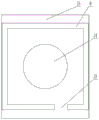
图2是本实用新型挡板结构示意图;Fig. 2 is the baffle structure schematic diagram of the present utility model;
图3是本实用新型压力传感器结构示意图;3 is a schematic structural diagram of the pressure sensor of the present invention;
图4是本实用新型卡具结构示意图;Fig. 4 is the structural schematic diagram of the fixture of the present invention;
附图说明:1、挡板,2、压力传感器,3、第一凸块,4、第一圆形槽,5、第一空腔,6、上表面,7、插头,8、壳体,9、侧表面,10、下表面,11、第二圆形槽,12、第二空腔,13、第二凸块,14、贴板,15、U形板,16、第一螺纹孔,17、螺栓,18、阶梯孔,19、U形槽,20、第二螺纹孔。Description of drawings: 1. Baffle plate, 2. Pressure sensor, 3. First bump, 4. First circular groove, 5. First cavity, 6. Upper surface, 7. Plug, 8. Housing, 9, side surface, 10, lower surface, 11, second circular groove, 12, second cavity, 13, second bump, 14, sticker, 15, U-shaped plate, 16, first threaded hole, 17. Bolt, 18, Step hole, 19, U-shaped groove, 20, Second threaded hole.
具体实施方式Detailed ways
下面将结合本实用新型实施例中的附图,对本实用新型实施例中的技术方案进行清楚、完整地描述,显然,所描述的实施例仅仅是本实用新型一部分实施例,而不是全部的实施例。基于本实用新型中的实施例,本领域普通技术人员在没有做出创造性劳动前提下所获得的所有其他实施例,都属于本实用新型保护的范围。The technical solutions in the embodiments of the present utility model will be clearly and completely described below with reference to the accompanying drawings in the embodiments of the present utility model. Obviously, the described embodiments are only a part of the embodiments of the present utility model, rather than all the implementations. example. Based on the embodiments of the present invention, all other embodiments obtained by those of ordinary skill in the art without creative work fall within the protection scope of the present invention.
一种铁路货车翻车机测试专用压力传感器,包括可检测压力的感应组件和可将感应组件固定的卡具,感应组件与卡具可拆卸连接,感应组件包括压力传感器2,本实施例中,压力传感器2为长方体,其中压力传感器2的长度和宽度相同,即压力传感器2的上表面6和下表面10是正方形,压力传感器2的上表面6可拆卸连接有挡板1,本实施例中,挡板1与上表面6接触的表面为正方形,并且其长度和宽度与上表面6的长度和宽度相同,挡板1与上表面6紧密接触,当挡板1受到外力作用时,会传到压力传感器2上,压力传感器2对其进行检测,压力传感器2的侧表面9上嵌有与外部设备连接的插头7,通过插头7将检测到的数据传到外部设备上,对所得数据进行分析;卡具包括与翻车机可拆卸连接的U形板15,U形板15通过紧定螺钉固定到翻车机上,U形板15包括底板以及垂直设置在底板两侧的侧板,底板的长度和宽度要大于压力传感器2的长度和宽度,在侧板上开设有若干个与紧定螺钉相对应的第一螺纹孔16,第一螺纹孔16的数量可以是1-4个,本实施例中数量选择1个,U形板15中部的外侧固定连接有可容纳感应组件的壳体8,即壳体8设置在底板外侧,本实施例中,壳体8由四个限位板90度拼接形成,并且焊接到卡具上,限位板的长度稍大于压力传感2的长度,保证压力传感器2顺利放入壳体,限位板的高度小于压力传感器2的高度,即压力传感器2的下部放置在壳体8中,其上部凸出壳体8,保证压力传感器8能够工作。A special pressure sensor for testing a railway freight car dumper, including a sensing component that can detect pressure and a fixture that can fix the sensing component. The sensing component and the fixture are detachably connected, and the sensing component includes a
对压力传感器2的上表面6作进一步限定:压力传感器2的上表面6中心位置开设有第一圆形槽4,第一圆形槽4的直径要小于压力传感器2的长度,第一圆形槽4的深度要远远小于压力传感器2的高度,第一圆形槽4中心位置固定连接有第一凸块3,第一凸块3为圆柱状,其直径小于第一圆形槽4的直径,第一凸块3的高度小于第一圆形槽4的深度,挡板1与压力传感器2之间形成第一空腔5,为挡板1提供变形空间。此时,挡板1与上表面6第一空腔5周侧部分紧密接触,即压力传感器通过周侧部分检测外力。The
对压力传感器2的下表面10作进一步限定:压力传感器2的下表面10中心位置开设有第二圆形槽11,本实施例中,第二圆形槽11的直径和深度与第一圆形槽4的直径和深度相同,第二圆形槽11中心位置固定连接有第二凸块13,第二凸块13的直径小于第二圆形槽11的直径,第二凸块13的高度大于第二圆形槽11的深度,压力传感器2与壳体8底部之间形成第二空腔12,此时,下表面10第二空腔12的周侧部分悬空,防止周侧部分与壳体8底部接触影响检测结果。The
为了进一步保证下表面10第二空腔12的周侧部分悬空,在壳体8底部中心位置固定连接有贴板14,贴板14为圆形板,且其直径不小于第二凸块13的直径,贴板14与第二凸块13可拆卸连接,本实施例中,第二凸块13粘贴到贴板14中心位置上,壳体8侧面开设有可供插头7伸出的U形槽19。In order to further ensure that the peripheral part of the
本实施例中,对挡板1和压力传感器2的连接方式作进一步限定:挡板1通过若干个螺栓17与压力传感器2连接,挡板1开设有若干个与螺栓17相对应的第二螺纹孔20,压力传感器2上开设有若干个阶梯孔18,螺栓17从下往上拧并且不伸出挡板1,保证挡板1表面平整。In this embodiment, the connection mode of the
对所公开的实施例的上述说明,使本领域专业技术人员能够实现或使用本实用新型。对这些实施例的多种修改对本领域的专业技术人员来说将是显而易见的,本文中所定义的一般原理可以在不脱离本实用新型的精神或范围的情况下,在其它实施例中实现。因此,本实用新型将不会被限制于本文所示的这些实施例,而是要符合与本文所公开的原理和新颖特点相一致的最宽的范围。The above description of the disclosed embodiments enables those skilled in the art to implement or use the present invention. Various modifications to these embodiments will be readily apparent to those skilled in the art, and the generic principles defined herein may be implemented in other embodiments without departing from the spirit or scope of the present invention. Thus, the present invention is not intended to be limited to the embodiments shown herein, but is to be accorded the widest scope consistent with the principles and novel features disclosed herein.
Claims (6)
Priority Applications (1)
| Application Number | Priority Date | Filing Date | Title |
|---|---|---|---|
| CN202122914090.3U CN216284048U (en) | 2021-11-25 | 2021-11-25 | A special pressure sensor for the test of railway freight car dumper |
Applications Claiming Priority (1)
| Application Number | Priority Date | Filing Date | Title |
|---|---|---|---|
| CN202122914090.3U CN216284048U (en) | 2021-11-25 | 2021-11-25 | A special pressure sensor for the test of railway freight car dumper |
Publications (1)
| Publication Number | Publication Date |
|---|---|
| CN216284048U true CN216284048U (en) | 2022-04-12 |
Family
ID=81036522
Family Applications (1)
| Application Number | Title | Priority Date | Filing Date |
|---|---|---|---|
| CN202122914090.3U Expired - Fee Related CN216284048U (en) | 2021-11-25 | 2021-11-25 | A special pressure sensor for the test of railway freight car dumper |
Country Status (1)
| Country | Link |
|---|---|
| CN (1) | CN216284048U (en) |
-
2021
- 2021-11-25 CN CN202122914090.3U patent/CN216284048U/en not_active Expired - Fee Related
Similar Documents
| Publication | Publication Date | Title |
|---|---|---|
| CN106129277B (en) | Power battery box with battery management system | |
| CN216284048U (en) | A special pressure sensor for the test of railway freight car dumper | |
| CN203241044U (en) | Non-contact printing circuit board flattening and detecting device | |
| CN213580484U (en) | Torsion test machine with impact test | |
| CN103449309B (en) | Sensing method for dynamic tracking of grab bucket load of ship unloader | |
| CN201000399Y (en) | Device for testing performance of jack | |
| CN207424148U (en) | A kind of power line carrier module multifunctional detecting device | |
| CN209945591U (en) | Elastic sheet elasticity detector | |
| CN102928882B (en) | A kind of automobile door lock body assembly parts leakage detection apparatus | |
| CN216901443U (en) | Pressure controller comprehensive test platform | |
| CN215177385U (en) | Detection tool for detecting sensor | |
| CN105486194B (en) | A kind of automobile catalytic device assembly checking tool | |
| CN209623937U (en) | A piezoresistive pressure sensor | |
| CN105445501A (en) | Electric detecting device for environmental testing | |
| CN202939315U (en) | Device for detecting neglected mounting of lock body assembly parts of automobile door lock | |
| CN111076864A (en) | Inspection structure for oil pressure sensor | |
| CN201852949U (en) | Detecting device | |
| CN215735153U (en) | Simple fool-proof structure | |
| CN2814433Y (en) | Automatic detecting device for battery short circuit | |
| CN108287260B (en) | Electric power measurement seal performance detection equipment | |
| CN217845466U (en) | Pressure detection system of car dumper | |
| CN216746573U (en) | Simple stress sensor testing device | |
| CN203587727U (en) | Functional glass false pressure test fixture | |
| CN207338499U (en) | A kind of new new energy car battery bag press fitting sensor | |
| CN204536015U (en) | Voltage output type high-speed train bogie unstability detecting sensor |
Legal Events
| Date | Code | Title | Description |
|---|---|---|---|
| GR01 | Patent grant | ||
| GR01 | Patent grant | ||
| CF01 | Termination of patent right due to non-payment of annual fee | ||
| CF01 | Termination of patent right due to non-payment of annual fee |
Granted publication date: 20220412 |