SUMMERY OF THE UTILITY MODEL
The utility model mainly aims to provide a sensor mounting structure, and aims to solve the technical problem that the position accuracy of a sensor is difficult to ensure when the sensor is assembled in some existing mobile equipment.
In order to achieve the purpose, the sensor mounting structure provided by the utility model comprises a mounting panel, a mounting shell and a sensor. The mounting panel is provided with a first positioning groove, and the bottom of the first positioning groove is provided with a first signal window; the mounting shell is positioned in the first positioning groove and is provided with a second signal window opposite to the first signal window; the sensor is installed in the installation shell and receives and transmits induction signals through the first signal window and the second signal window.
In an embodiment, a surface of the mounting shell facing the first signal window is further provided with a first positioning boss, and the second signal window is arranged in the first positioning boss; the first positioning groove is arranged on the first side wall of the base, the second positioning groove is arranged on the second side wall of the base, the first signal window is arranged at the bottom of the second positioning groove, and the first positioning table is positioned in the second positioning groove.
In an embodiment, the mounting shell has a mounting cavity for accommodating the sensor, and a third positioning groove is formed in the mounting cavity corresponding to the second signal window; the sensor comprises a circuit board and a transceiver convexly arranged on the surface of the circuit board, and the transceiver is positioned in the third positioning groove.
In an embodiment, a first rubber pad is further installed between the sensor and the cavity wall of the installation cavity, and the third positioning groove penetrates through the first rubber pad.
In an embodiment, a fourth positioning groove is further formed in the mounting cavity corresponding to the cavity wall of the second signal window, and a second positioning boss is arranged on the first rubber pad corresponding to the fourth positioning groove; the third positioning groove is located in the second positioning boss, and the second positioning boss is located in the fourth positioning groove.
In one embodiment, the transceiver includes a transmitting lens and a receiving lens, and a separating structure is further disposed between the transmitting lens and the receiving lens, and extends from the sensor to the second signal window and separates the transmitting lens from the receiving lens.
In one embodiment, the separating structure includes a first separating arm formed within the third detent and a second separating arm formed within the second signal window.
In an embodiment, a filter lens is further installed in the second signal window, and the filter lens is embedded in the first positioning boss and abuts against one end of the separation structure.
In an embodiment, the mounting shell includes a first shell and a second shell, the first shell is provided with a mounting cavity for accommodating the sensor, a mounting port communicating with the mounting cavity, and the second signal window, and the second shell is mounted at the mounting port of the first shell.
In an embodiment, the first housing is provided with a first clamping structure, and the second housing is provided with a second clamping structure clamped with the first clamping structure.
In one embodiment, the sensor further comprises a second rubber pad, and the second rubber pad is pressed between the second shell and the sensor.
In an embodiment, the mounting panel is further provided with a first screw connection structure, and the second housing is further provided with a second screw connection structure in screw connection with the first screw connection structure.
In an embodiment, the first screw connection structure is a screw connection column having a screw connection hole, the second screw connection structure has a fifth positioning slot accommodating the screw connection column, and the screw connection hole penetrates through the bottom of the fifth positioning slot.
In an embodiment, at least two of the sensors are disposed on the mounting panel, and each of the sensors is mounted on the mounting panel through one of the mounting cases.
The present invention also provides a mobile device, wherein the sensor mounting structure of the mobile device comprises:
the mounting panel is provided with a first positioning groove, and a first signal window is arranged at the bottom of the first positioning groove;
the mounting shell is positioned in the first positioning groove and is provided with a second signal window opposite to the first signal window; and the number of the first and second groups,
and the sensor is arranged in the mounting shell and receives and transmits induction signals through the first signal window and the second signal window.
The sensor mounting structure firstly mounts the sensor in the mounting shell, then positions the sensor and the mounting shell on the mounting panel of the mobile equipment, and the mounting panel is provided with a first positioning groove for positioning the mounting shell. And then when the location, directly will install the shell location in first constant head tank, can realize the accurate positioning of sensor. Compared with the installation mode of directly installing the sensor which is small in size, thin in thickness and not easy to fix on the installation panel, the installation mode of installing the sensor through the installation shell and the first positioning groove can improve the position accuracy and convenience in installation of the sensor, and the sensor can be protected through the installation shell. The technical problem that the position accuracy of the sensor is difficult to guarantee when the sensor is assembled by some existing mobile devices is effectively solved.
Detailed Description
It should be noted that, if directional indications (such as up, down, left, right, front, and back … …) are involved in the embodiment of the present invention, the directional indications are only used to explain the relative positional relationship between the components, the movement situation, and the like in a specific posture (as shown in the drawing), and if the specific posture is changed, the directional indications are changed accordingly.
In addition, if there is a description of "first", "second", etc. in an embodiment of the present invention, the description of "first", "second", etc. is for descriptive purposes only and is not to be construed as indicating or implying relative importance or implicitly indicating the number of technical features indicated. Thus, a feature defined as "first" or "second" may explicitly or implicitly include at least one such feature. In addition, the meaning of "and/or" appearing throughout is to include three juxtapositions, exemplified by "A and/or B" including either scheme A, or scheme B, or a scheme in which both A and B are satisfied. In addition, technical solutions between various embodiments may be combined with each other, but must be realized by a person skilled in the art, and when the technical solutions are contradictory or cannot be realized, such a combination should not be considered to exist, and is not within the protection scope of the present invention.
The present invention provides a sensor mounting structure 10.
The sensor mounting structure 10 provided by the utility model can be applied to mobile equipment needing obstacle avoidance through a sensor, such as a sweeping robot, an intelligently movable air purifier, a humidifier, an air conditioner and the like. Specifically, during walking, the mobile device usually needs to sense a static or dynamic obstacle existing on a planned route thereof through a sensor, and then update the route in real time according to a certain algorithm to bypass the obstacle, or temporarily stop traveling until the obstacle leaves the planned route, continue traveling, and finally move to a target point.
Sensors used for obstacle avoidance on mobile equipment are generally infrared sensors, laser sensors, ultrasonic sensors, vision sensors and the like, different sensor types have different advantages and disadvantages, and selection can be performed according to the working requirements of the mobile equipment in actual design. Regardless of the type of sensor, the sensing principle of the surrounding obstacle is basically related to the position relationship between the sensor itself and the obstacle, such as the distance relationship, the orientation relationship, the size relationship, and the like between the sensor and the obstacle. Therefore, the positional accuracy when the sensor is mounted on the mobile device is particularly important, otherwise it is easy for the mobile device 70 to hit an obstacle due to a sensing deviation. However, in some existing mobile devices, it is difficult to ensure the position accuracy of the sensor during installation due to the influence of installation process, size, fixing manner, and other factors. The sensor mounting structure 10 of the present invention is proposed to improve the positional accuracy of the sensor at the time of mounting.
Specifically, in the embodiment of the present invention, as shown in fig. 2 to 6, the sensor mounting structure 10 includes a mounting panel 20, a mounting case 30, and a sensor 40. The mounting panel 20 of the present invention refers to a structure or a part of a structure such as a housing, a decorative plate, a bezel, or a cover plate, to which the sensor 40 is connected when the sensor 40 is assembled to the mobile device 70, and may be referred to as the mounting panel 20 of the present invention.
As shown in fig. 1, for example, a mobile device 70 is taken as a mobile humidifier, which includes a mobile chassis 71 and a function module 72 mounted on the mobile chassis 71. The movable chassis 71 mainly comprises a disk body, rollers rotatably mounted on the disk body, and a driving motor for driving the rollers to roll, wherein the driving motor drives the rollers to roll to drive the movable chassis 71 to move, and then the movable chassis 71 drives the functional module 72 to move.
The functional module 72 mainly includes a hollow housing, a centrifugal fan installed in the housing, a humidifying component installed at an air inlet of the centrifugal fan, an air guide grille 73 installed at an air outlet of the centrifugal fan, and the like. Wherein, the shell is the enclosed type or partly encloses the enclosed type panel structure to mainly used holding and protection centrifugal fan, humidification part etc. the position that corresponds the centrifugal fan air intake on this shell is provided with ventilation mesh 74, and the upper end of shell is the opening setting and is used for supplying air guide grid 73 to install. The inner surface of the housing is provided with the sensor 40, the control panel and other components, so that the housing is the mounting panel 20 of the present invention, or the part of the housing where the sensor 40 is mounted is the mounting panel 20 of the present invention.
Generally, the sensor 40 is generally installed on a panel in the forward direction of the mobile device 70, and of course, in the case that the mobile device 70 travels via a universal wheel and needs to go forward, go backward or turn at any time, the sensor 40 needs to be installed on the installation panel 20 in different directions of the mobile device 70 according to actual conditions to ensure that the mobile device 70 can smoothly move to the destination according to the preset route.
In the present embodiment, as shown in fig. 4, the mounting panel 20 is provided with a first positioning groove 21, and the bottom of the first positioning groove 21 is provided with a first signal window 22. Specifically, the mounting panel 20 in the present embodiment has a substantially semi-enclosed panel structure, and includes a first panel surface and a second panel surface that are opposite to each other, and a third panel surface connected between the first panel surface and the second panel surface. The first plate surface and the second plate surface are respectively arranged opposite to the air inlet of the centrifugal fan and are respectively provided with a ventilating mesh.
The first positioning groove 21 is formed on the inner side of the third plate surface (i.e., the side having the first plate surface and the second plate surface), and the first positioning groove 21 is used for positioning the mounting case 30 on which the sensor 40 is mounted. Therefore, the shape, size, depth, etc. of the first positioning groove 21 can be designed according to the mounting housing 30, for example, in the present embodiment, the mounting housing 30 for mounting the sensor 40 has a substantially rectangular column structure, and thus the first positioning groove 21 has a rectangular groove shape. With respect to the depth of the first positioning groove 21, in some embodiments, the depth of the first positioning groove 21 is approximately between one tenth and one fifth of the height of the mounting shell 30, which can better position the mounting shell 30 and also facilitate the mounting shell 30 to be installed in the first positioning groove 21. The situation that the first positioning groove 21 is too shallow to well position the mounting shell 30 and the situation that the friction is large and the requirement on the mounting angle is high when the mounting shell 30 is installed due to too deep first positioning groove 21 are avoided. Wherein, to the installation shell 30 of rectangle cylinder structure, four angles of installation shell 30 can the radius setting, and is corresponding, four angles of first constant head tank 21 also radius setting, so can enough reduce first constant head tank 21 to the friction of installation shell 30, scrape bump etc. still be convenient for install packing into of shell 30 more.
The first positioning groove 21 may be formed in various ways, for example, by a groove concavely formed on the surface of the mounting panel 20, a fence convexly formed on the surface of the mounting panel 20, or other structures on the mounting panel 20, such as a rib, a guide bar, and a grating. The specific design may be flexible according to the actual structure of the mounting panel 20, and is not limited in this respect.
In the present embodiment, as shown in fig. 4, in order to ensure that the sensor 40 installed inside the installation panel 20 (i.e., the side on which the centrifugal fan or other functional components are installed) can emit a signal to the outside of the installation panel 20 or receive a signal from the outside of the installation panel 20, the bottom of the first positioning groove 21 is further provided with a first signal window 22. The first signal window 22 may be formed by a through hole penetrating the mounting panel 20, may be formed by a structure penetrating the mounting panel 20 and having a lens or a light transmitting member mounted therein, or may be formed by a transparent installation of a partial region on the mounting panel 20. The specific design can be carried out according to actual needs, and is not limited herein.
The shape, size, etc. of the first signal window 22 are not limited herein, and only enough sensor 40 needs to transmit and receive the sensing signal, for example, in the present embodiment, the first signal window 22 has a substantially square structure and is formed by a through hole penetrating the mounting panel 20. The sensor 40 generally includes a transceiver 42, and the size of the first signal window 22 is substantially matched with the transceiver 42 of the sensor 40, so as to ensure smooth signal transceiving, simplify the processing technology and improve the production efficiency.
The mounting housing 30 is positioned in the first positioning groove 21 and is provided with a second signal window 31 opposite to the first signal window 22. In this embodiment, the positioning of the mounting shell 30 in the first positioning groove 21 means that the mounting shell 30 is positioned on the mounting panel 20 by the first positioning groove 21. For example, the size and shape of first constant head tank 21 follow installation shell 30 adaptation, and when installation shell 30 was installed in first constant head tank 21, the outer wall of installation shell 30 and the inner wall butt of first constant head tank 21 or the small clearance interval, first constant head tank 21 had both played the positioning action to installation shell 30, also can play certain supporting role.
Still alternatively, the first positioning groove 21 may be larger than the mounting shell 30, and a rubber pad is disposed between an outer wall of the mounting shell 30 and an inner wall of the first positioning groove 21, so that the mounting shell 30 can be clamped in the first positioning groove 21 through the rubber pad, and thus, the positioning of the mounting shell 30 in the first positioning groove 21 can also be achieved.
In this embodiment, in order to avoid the situation that the mounting shell 30 shakes during the positioning process, the bottom of the first positioning groove 21 and the bottom of the mounting shell 30 (i.e. the surface facing the first signal window 22) can be both configured as planes and abut against each other, so that the positioning stability of the mounting shell 30 in the first positioning groove 21 can be ensured.
The second signal window 31 of the mounting housing 30 is formed, sized, shaped, etc. with reference to the first signal window 22, and will not be described in detail. The second signal window 31 and the first signal window 22 may be formed in the same manner or in different manners. For example, in the present embodiment, the filter lens 313 is disposed in the second signal window 31, and the first signal window 22 is directly formed by a through hole penetrating the mounting panel 20.
The second signal window 31 and the first signal window 22 need to be correspondingly arranged in position to ensure that the sensor 40 in the mounting shell 30 can receive and transmit induction signals through the second signal window 31 and the first signal window 22.
As shown in fig. 6 and 7, the sensor 40 is installed in the mounting case 30, and transmits and receives an induction signal through the first signal window 22 and the second signal window 31. Specifically, a mounting cavity 33 is formed in the mounting shell 30, the second signal window 31 is disposed on a wall of the mounting cavity 33, and the sensor 40 is positioned in the mounting cavity 33 of the mounting shell 30. The sensor 40 is provided with a transceiver 42 for transmitting and receiving signals, and the transceiver 42 of the sensor 40 corresponds in position to the second signal window 31 when the sensor 40 is positioned in the mounting cavity 33.
In order to enable the sensor 40 to be mounted in the mounting cavity 33, as shown in fig. 7 and 8, the mounting case 30 may be provided with a mounting opening 352 communicating with the mounting cavity 33 thereof, and after the sensor 40 is mounted in the mounting cavity 33, the mounting opening 352 is covered by a cover plate or the like to prevent the sensor 40 from being detached from the mounting cavity 33 from the mounting opening 352 of the mounting case 30. Alternatively, the mounting case 30 may be composed of two cases detachably connected, one of the cases is provided with the mounting cavity 33 and the mounting opening 352, and after the sensor 40 is mounted in the mounting cavity 33, the sensor 40 may be pressed in the mounting cavity 33 from the mounting opening 352 by the other case to ensure the mounting stability of the sensor 40.
Of course, from the viewpoint of improving the installation stability of the sensor 40, a positioning structure, a protective rubber pad, and the like may be further disposed in the installation shell 30, so that the sensor 40 is stably installed and can be better protected.
Therefore, in summary, it can be understood that the sensor mounting structure 10 of the present invention first mounts the sensor 40 in the mounting housing 30, and then positions the sensor 40 on the mounting panel 20 of the mobile device 70 together with the mounting housing 30, and the mounting panel 20 is provided with the first positioning groove 21 for positioning the mounting housing 30. When positioning, the mounting housing 30 is directly positioned in the first positioning groove 21, so that the sensor 40 can be accurately positioned. Compared with the installation mode of directly installing the sensor 40 which is small in size, thin in thickness and not easy to fix on the installation panel 20, the installation mode of installing the sensor 40 through the installation shell 30 and the first positioning groove 21 not only can improve the position accuracy and convenience of installation of the sensor 40, but also can protect the sensor 40 through the installation shell 30. The technical problem that the position accuracy of the sensor 40 is difficult to ensure when the sensor 40 is assembled by some existing mobile devices 70 is effectively solved.
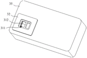
In an embodiment, please refer to fig. 4 to 6 and fig. 9 to 10, a first positioning boss 32 is further disposed on a surface of the mounting shell 30 facing the first signal window 22, and the second signal window 31 is disposed in the first positioning boss 32; the bottom of the first positioning groove 21 is further provided with a second positioning groove 23, the first signal window 22 is arranged at the bottom of the second positioning groove 23, and the first positioning table is positioned in the second positioning groove 23.
In the present embodiment, taking the surface of the mounting housing 30 facing the first signal window 22 as an example of a bottom surface, the first positioning bosses 32 are protruded from the bottom surface of the mounting housing 30, and are similar to the mounting housing 30 in shape and are all rectangular structures. The first positioning boss 32 is positioned in the second positioning groove 23, the bottom surface of the first positioning boss abuts against the bottom of the second positioning groove 23, and the outer peripheral wall of the first positioning boss abuts against the inner peripheral wall of the second positioning groove 23 or a small gap is formed between the outer peripheral wall of the first positioning boss and the inner peripheral wall of the second positioning groove 23.
It can be understood that, because the first signal window 22 is disposed at the bottom of the second positioning groove 23, the second signal window 31 is disposed in the first positioning boss 32, and thus when the first positioning boss 32 is positioned in the second positioning groove 23, the position accuracy between the first signal window 22 and the second signal window 31 can be further ensured. When the mounting shell 30 is positioned in the first positioning groove 21, the situation of alignment deviation between the first signal window 22 and the second signal window 31 is avoided, and the position accuracy of the sensor 40 during mounting is ensured.
In an embodiment, please refer to fig. 6, 11 to 14, the mounting housing 30 has a mounting cavity 33 for accommodating the sensor 40, and a third positioning slot 51 is disposed in the mounting cavity 33 corresponding to the second signal window 31; the sensor 40 includes a circuit board 41 (alternatively referred to as a detection chip or the like) and a transceiver 42 protruding from the surface of the circuit board 41, and the transceiver 42 is located in the third positioning slot 51.
In this embodiment, the third positioning groove 51 may be formed in various manners, for example, the third positioning groove 51 may be directly formed by a groove concavely formed on the cavity wall of the installation cavity 33, or may be formed by other components positioned in the installation cavity 33, for example, in an embodiment, a first rubber pad 50 is further installed between the sensor 40 and the cavity wall of the installation cavity 33, the third positioning groove 51 penetrates through the first rubber pad 50, and then on the basis of protecting the sensor 40 by the first rubber pad 50, the transceiver 42 on the sensor 40 can be positioned by the third positioning groove 51 in the first rubber pad 50. The positional accuracy of the sensor 40 (and more particularly the transceiver 42) is ensured, thereby ensuring the obstacle avoidance function of the mobile device 70.
In the above embodiment, the circuit board 41 of the sensor 40 has a substantially rectangular configuration, and a plurality of components including the transceiver 42 are projected from the circuit board 41. Therefore, in order to make the first rubber pad 50 better protect the entire sensor 40, the first rubber pad 50 has a substantially square frame structure with a hollow interior, and the size of the first rubber pad is adapted to the circuit board 41 of the sensor 40. The hollow inner space of the first rubber pad 50 is used for avoiding and surrounding each component protruding from the circuit board 41, so as to protect each component on the circuit board 41. The first rubber pad 50 has a certain thickness to prevent the circuit board 41 from directly contacting the wall of the installation cavity 33, and prevent the circuit board 41 from being hard extruded or the components on the circuit board 41 from being hard extruded or damaged.
The third positioning slot 51 is formed in the position of the first rubber pad 50 corresponding to the second signal window 31, when the surface of the circuit board 41 abuts against the frame of the rubber pad, the transceiver 42 on the circuit board 41 is positioned to the third positioning slot 51, and the wall of the third positioning slot 51 can be elastically attached to the outer wall of the transceiver 42.
In an embodiment, please refer to fig. 6, 10 to 12, in order to ensure the position accuracy between the third positioning groove 51 and the second signal window 31, a fourth positioning groove 34 is further disposed in the mounting cavity 33 corresponding to the cavity wall of the second signal window 31, and the second signal window 31 is located at the bottom of the fourth positioning groove 34. A second positioning boss 52 is arranged at a position of the first rubber pad 50 corresponding to the fourth positioning groove 34; the third positioning groove 51 is located in the second positioning boss 52, specifically, the third positioning groove penetrates through the second positioning boss 52, and the second positioning boss 52 is located in the fourth positioning groove 34.
When the sensor 40 and the mounting case 30 in this embodiment are assembled, the first rubber mat 50 is mounted in the mounting cavity 33, and the second positioning boss 52 on the first rubber mat 50 is embedded in the fourth positioning groove 34, so that the first rubber mat 50 is accurately positioned in the mounting cavity 33. Then, the sensor 40 is mounted on the side of the first rubber pad 50 opposite to the second signal window 31, and the transceiver 42 on the sensor 40 is correspondingly mounted in the third positioning slot 51, so that the accurate positioning of the whole sensor 40 in the mounting cavity 33 is realized.
It will be appreciated that the transceiver 42 of the sensor 40 is positioned in the third positioning groove 51 of the first rubber mat 50, the third positioning groove 51 penetrates the second positioning boss 52, the second positioning boss 52 is positioned in the fourth positioning groove 34, and the bottom of the fourth positioning groove 34 is provided with the second signal window 31. That is, the transceiver 42 of the sensor 40 and the second signal window 31 are positioned by a plurality of positioning structures, so that multiple guarantees are provided during positioning, the relative position accuracy between the transceiver 42 and the second signal window 31 is ensured, and the position accuracy of the whole sensor 40 is further realized. Meanwhile, the first rubber mat 50 and the mounting shell 30 also play a role in protecting the sensor 40, and the sensor 40 is prevented from being collided, damaged or displaced.
In an embodiment, please refer to fig. 6, 13 and 14, the transceiver 42 includes a transmitting lens 421 and a receiving lens 422, the transmitting lens 421 is used for transmitting the sensing signal, and the receiving lens 422 is used for receiving the reflected sensing signal, that is, the transmitting lens 421 and the receiving lens 422 correspond to different signals respectively. Therefore, in order to avoid the situations of mutual crossing, mutual interference and the like of the transmitting signal and the receiving signal, a separation structure is further disposed between the transmitting lens 421 and the receiving lens 422, and the separation structure extends from the sensor 40 to the second signal window 31 and separates the transmitting lens 421 and the receiving lens 422.
Specifically, in this embodiment, the separating structure may be a plate-shaped structure or a block-shaped structure, and is used to separate the transmitting lens 421 and the receiving lens 422, and separate the second signal window 31 into two sub-windows, where one sub-window corresponds to the transmitting lens 421, and the other sub-window corresponds to the receiving lens 422. Therefore, the signals transmitted by the transmitting lens 421 and the signals received by the receiving lens 422 can be ensured not to cross or interfere with each other, and the accurate sensing of the obstacles can be ensured.
It should be noted that the separation structure can be a separate component and is mounted between the transmitting lens 421 and the receiving lens 422 when assembled. Alternatively, the partition structure may be formed by the structure of the sensor 40 itself, and when assembled, extends into the third positioning groove 51 together with the transmitting lens 421 and the receiving lens 422, and extends up to the second signal window 31.
Still alternatively, the partition structure may be formed by the first rubber pad 50 and/or a structure on the mounting case 30, for example, in an embodiment, the partition structure includes a first partition arm 53 and a second partition arm 312, the first partition arm 53 is formed in the third positioning slot 51 and divides the third positioning slot 51 into two sub-slots. The second partition arm 312 is formed in the second signal window 31, and specifically, in the present embodiment, the second signal window 31 includes a signal through hole 311, and the signal through hole 311 penetrates through the groove bottom of the fourth positioning groove 34. A second separating arm 312 is formed in the signal via 311 and separates the signal via 311 into two sub-holes. When the second positioning boss 52 on the first rubber pad 50 is positioned in the fourth positioning groove 34, the first separating arm 53 in the third positioning groove 51 and the second separating arm 312 in the second signal window 31 are abutted against each other, and then the space between the transceiver 42 and the second signal window 31 are separated into two signal channels by the separating structure formed by the first separating arm 53 and the second separating arm 312. One signal channel is used for the transmitting lens 421 to transmit the sensing signal, and the other signal channel is used for the receiving lens 422 to receive the sensing signal.
In an embodiment, a filter lens 313 is further installed in the second signal window 31, and the filter lens 313 is embedded in the first positioning boss 32 and abuts against one end of the separation structure. In this embodiment, the sensor 40 is an infrared sensor or a laser sensor, and the filter lens 313 allows signal light to pass through, and can prevent other light from passing through, so as to prevent the signal light from being interfered, and ensure that the sensor 40 can accurately sense an obstacle.
The filter lens 313 may be completely embedded in the first positioning boss 32, for example, flush with the surface of the first positioning boss 32 after being embedded, so that the installation stability of the filter lens 313 may be ensured.
In one embodiment, as shown in fig. 6, 7 or 10, the mounting shell 30 includes a first housing 35 and a second housing 36, the first housing 35 has a substantially rectangular box-shaped structure and is provided with a mounting cavity 33 for accommodating the sensor 40, a mounting opening 352 communicating with the mounting cavity 33, and the second signal window 31 opposite to the mounting opening 352, and the second housing 36 is mounted at the mounting opening 352 of the first housing 35 to prevent the sensor 40 from being separated from the mounting cavity 33 from the mounting opening 352. It will be appreciated that by having the mounting housing 30 comprised of the first and second housings 35, 36, not only is it possible to facilitate pre-mounting and pre-positioning of the sensor 40, but it is also possible to better protect the sensor 40.
The second housing 36 can be mounted at the mounting hole 352 of the first housing 35 by means of screw joint, adhesion, clamping, etc., and the specific mounting manner can be set according to actual needs. For example, in an embodiment, please refer to fig. 6 to 8 and fig. 15, a first clamping structure 351 is disposed on the first housing 35, and a second clamping structure 361 clamped with the first clamping structure 351 is disposed on the second housing 36. Specifically, when the second housing 36 is installed at the installation opening 352 of the first housing 35, a portion of the second housing 36 extends into the installation cavity 33 of the first housing 35, a clamping groove is formed in the portion of the second housing 36 extending into the installation cavity 33, a buckle is arranged on the wall of the installation cavity 33 corresponding to the clamping groove, the buckle is clamped in the clamping groove, and therefore clamping connection between the first housing 35 and the first housing 35 is achieved. It can be understood that the assembly process between the first housing 35 and the second housing 36 is more simple and convenient by means of the snap-fit.
Of course, in other embodiments, the first housing 35 may also be provided with a locking groove, and the second housing 36 may be provided with a locking buckle; or, the first housing 35 may also be provided with both a clamping groove and a buckle, and the second housing 36 may be provided with a corresponding buckle and a clamping groove, so as to improve the clamping stability between the first housing 35 and the second housing 36.
In one embodiment, as shown in fig. 6 and 7, the sensor mounting structure 10 further includes a second rubber mat 60, the second rubber mat 60 being compressed between the second housing 36 and the sensor 40. In this embodiment, the sensor 40 includes a rectangular circuit board 41 and a plurality of components protruding from the circuit board 41, and the second rubber pad 60 is a hollow rectangular frame structure and is adapted to the size of the circuit board 41. The second rubber pad 60 abuts on the periphery of the circuit board 41 and surrounds the components mounted on the circuit board 41 in a hollow space. After the second housing 36 is mounted to the mounting opening 352 of the first housing 35, the second rubber pad 60 is pressed against the circuit board 41 of the sensor 40, i.e., the second rubber pad 60 is sandwiched between the second housing 36 and the sensor 40. And then not only make sensor 40 can install more stably, can also play certain guard action to sensor 40 through second cushion 60.
In order to enable the second housing 36 to accurately and effectively press the second rubber pad 60, the surface of the second housing 36 facing the second rubber pad 60 is formed with an annular protruding structure which is matched with the second rubber pad 60 in size and presses the second rubber pad 60 when the second housing 36 is clamped to the first housing 35. The above-mentioned locking groove can also be arranged on the side wall of the protruding structure. In addition, the middle part of the second casing 36 may also be hollow, so as to avoid interference when assembling on the first casing 35 for each component protruding on the sensor 40.
In an embodiment, please refer to fig. 2 and fig. 6, the mounting panel 20 is further provided with a first screw structure 24, and the second housing 36 is further provided with a second screw structure 362 screwed with the first screw structure 24. And then the whole mounting case 30 is mounted in the first positioning groove 21 of the mounting panel 20, the fixing of the mounting case 30 on the mounting panel 20 can be achieved directly by the screwing of the first and second screwing structures 24 and 362.
In the embodiment, the first screwing structure 24 and the second screwing structure 362 are screwing holes, and after the two screwing holes are aligned, screwing is performed by using bolts or screws.
In addition, in this embodiment, the second housing 36 is substantially rectangular and has four side surfaces, two opposite side surfaces of the second housing are respectively provided with a clamping groove for clamping with the first housing 35, and the other two opposite side surfaces of the second housing are respectively provided with the second screw connection structure 362, so that the stress of the whole mounting shell 30 during assembly can be ensured to be more balanced, and the mounting stability of the mounting shell 30 can be ensured.
In an embodiment, the first screw structure 24 is a screw post having a screw hole, the second screw structure 362 has a fifth positioning slot 363 for accommodating the screw post, and the bottom of the fifth positioning slot 363 has a screw hole therethrough. In the present embodiment, when the entire installation shell 30 is installed on the installation panel 20, in addition to the positioning of the entire installation shell 30 by the first positioning groove 21, the installation shell 30 is also positioned by the positioning between the fifth positioning groove 363 and the bolt-on column (i.e. the first bolt-on structure 24), that is, by multiple sets of positioning structures, so that the position accuracy of the installation shell 30 and the sensor 40 is further ensured.
And when the second screwing structure 362 accommodates the first screwing structure 24 through the fifth positioning slot 363, the screwing process is faster, and the installation shell 30 does not need to be continuously adjusted in order to align the screwing hole on the first screwing structure 24 with the screwing hole on the second screwing structure 362 accurately.
In one embodiment, as shown in fig. 2, at least two sensors 40 are disposed on the mounting panel 20, and each sensor 40 is mounted on the mounting panel 20 through one of the mounting housings 30. For example, two, three, five, nine, etc. may be provided, and the specific number of settings may be designed according to the size, motion environment, etc. of the mobile device 70. For example, in the present embodiment, five sensors 40 are disposed on the mounting panel 20, and are arranged in an arrangement manner of "two sensors are disposed side by side at the upper side, one sensor is disposed in the middle, and two sensors are disposed side by side at the lower side". Therefore, not only can the surrounding obstacles be sensed in a larger range, but also the cost can be reduced, and the situation that the cost is higher due to the excessive number of the sensors 40 is avoided
The present invention further provides a mobile device 70, where the mobile device 70 has the sensor mounting structure 10 of the foregoing embodiment, and since the mobile device 70 adopts all technical solutions of all the foregoing embodiments, at least all beneficial effects brought by the technical solutions of the foregoing embodiments are achieved, and details are not repeated herein.
The present invention further provides an air conditioner (not shown), which includes a main unit and a mobile device 70, wherein the main unit is provided with an accommodating cavity, the mobile device 70 is detachably accommodated in the accommodating cavity of the main unit, and the air conditioner has the sensor mounting structure 10 of the foregoing embodiment.
In this embodiment, the main unit of the air conditioner is mainly a vertical air conditioner indoor unit, and an accommodating cavity is disposed at one end of the main unit close to the ground. The mobile device 70 may be a sub-air conditioner, a sterilization device, a humidifier, an air cleaner, etc., and may be detachably received in the receiving chamber of the main unit. In operation, the mobile device 70 may be moved away from the host to other locations in the room.
The above description is only a preferred embodiment of the present invention, and not intended to limit the scope of the present invention, and all modifications and equivalents of the technical solutions of the present invention, which are made by using the contents of the present specification and the accompanying drawings, or directly/indirectly applied to other related technical fields, are included in the scope of the present invention.