CN215510601U - Sealed sand blasting machine - Google Patents
Sealed sand blasting machine Download PDFInfo
- Publication number
- CN215510601U CN215510601U CN202121020972.9U CN202121020972U CN215510601U CN 215510601 U CN215510601 U CN 215510601U CN 202121020972 U CN202121020972 U CN 202121020972U CN 215510601 U CN215510601 U CN 215510601U
- Authority
- CN
- China
- Prior art keywords
- door
- air bag
- annular air
- organism
- close
- Prior art date
- Legal status (The legal status is an assumption and is not a legal conclusion. Google has not performed a legal analysis and makes no representation as to the accuracy of the status listed.)
- Active
Links
- 238000005488 sandblasting Methods 0.000 title claims abstract description 20
- 238000007789 sealing Methods 0.000 claims abstract description 71
- 230000007246 mechanism Effects 0.000 claims abstract description 59
- IJGRMHOSHXDMSA-UHFFFAOYSA-N Atomic nitrogen Chemical compound N#N IJGRMHOSHXDMSA-UHFFFAOYSA-N 0.000 claims description 24
- 238000009434 installation Methods 0.000 claims description 7
- 229910001873 dinitrogen Inorganic materials 0.000 claims description 4
- 230000007306 turnover Effects 0.000 claims description 4
- 238000005422 blasting Methods 0.000 claims 2
- 230000000694 effects Effects 0.000 abstract description 13
- 229910052757 nitrogen Inorganic materials 0.000 description 10
- 239000004576 sand Substances 0.000 description 8
- 239000000463 material Substances 0.000 description 7
- 239000007789 gas Substances 0.000 description 5
- 230000032683 aging Effects 0.000 description 4
- 238000001125 extrusion Methods 0.000 description 4
- 239000011248 coating agent Substances 0.000 description 3
- 238000000576 coating method Methods 0.000 description 3
- 230000008602 contraction Effects 0.000 description 3
- 230000002035 prolonged effect Effects 0.000 description 3
- 238000005299 abrasion Methods 0.000 description 2
- 230000009471 action Effects 0.000 description 2
- 238000000034 method Methods 0.000 description 2
- 239000000853 adhesive Substances 0.000 description 1
- 230000001070 adhesive effect Effects 0.000 description 1
- 230000009286 beneficial effect Effects 0.000 description 1
- 230000003749 cleanliness Effects 0.000 description 1
- 230000006835 compression Effects 0.000 description 1
- 238000007906 compression Methods 0.000 description 1
- 238000005034 decoration Methods 0.000 description 1
- 230000002349 favourable effect Effects 0.000 description 1
- 230000006872 improvement Effects 0.000 description 1
- 210000003141 lower extremity Anatomy 0.000 description 1
- 230000004048 modification Effects 0.000 description 1
- 238000012986 modification Methods 0.000 description 1
- 230000008569 process Effects 0.000 description 1
- 230000009467 reduction Effects 0.000 description 1
- 230000035882 stress Effects 0.000 description 1
- 230000001360 synchronised effect Effects 0.000 description 1
Images


Landscapes
- Specific Sealing Or Ventilating Devices For Doors And Windows (AREA)
Abstract
The utility model relates to the technical field of sand blasting machines, and discloses a sealed sand blasting machine which comprises a machine body with a side opening and a machine door which is arranged on the side opening in an up-and-down overturning manner to open or close the side opening, wherein a sealing mechanism is arranged between the machine door and the machine body, the sealing mechanism comprises a first baffle plate, an annular air bag and a second baffle plate, the first baffle plate is arranged on the outer wall of the machine body and extends outwards in the circumferential direction around the side opening, the annular air bag is fixedly arranged on the side wall of the first baffle plate, the second baffle plate extends outwards in the circumferential direction around the side opening on the inner wall of the machine door and extends towards the direction close to the machine body, a sealing space for expanding the annular air bag is arranged between the second baffle plate and the first baffle plate, the inflation or deflation of the annular air bag is controlled by a control mechanism, and the sealed sand blasting machine can ensure the sealing effect and prolong the service life of the sealing mechanism.
Description
Technical Field
The utility model relates to the technical field of sand blasting machines, in particular to a sealed sand blasting machine.
Background
The sand blasting machine ensures that the surface of a workpiece obtains certain cleanliness and different roughness through the impact and cutting action of an abrasive on the surface of the workpiece, and the mechanical property of the surface of the workpiece is improved, so the fatigue resistance of the workpiece is improved, the adhesive force between the workpiece and a coating is increased, the durability of a coating is prolonged, and the leveling and decoration of a coating are facilitated.
Chinese patent with application number CN201921022031.1 discloses an upward-opening sand blasting machine, including an upward-turning cabinet door, upward-turning cabinet door includes first section cabinet door and second section cabinet door of hub connection, the top edge of first section cabinet door is connected with sand blasting machine cabinet body hub connection, the lower limb of first section cabinet door is connected with the top edge hub connection of second section cabinet door, be fixed with an air spring on the sand blasting machine cabinet body, the other end of air spring is fixed on first section cabinet door, the air spring is used for keeping the open or closed state of upward-turning cabinet door, upward-turning cabinet door is fixed with the sealing strip all around.
The sand blasting machine with the upward opening door changes the opening mode of the door into the upward turning mode, the sealing strip is arranged to realize sealing of the sand blasting machine, the sealing strip is fixed to the periphery of the cabinet door, when the sand blasting machine operates, the sprayed sand directly collides and rubs with the sealing strip, damage or aging of the sealing strip is accelerated, and the sealing performance of the sealing strip is reduced or the sealing effect is lost.
SUMMERY OF THE UTILITY MODEL
The utility model aims to provide a sealed sand blasting machine, which can ensure the sealing effect and prolong the service life of a sealing mechanism.
In order to achieve the purpose, the utility model provides the following technical scheme: the utility model provides a sealed sand blasting machine, set up in order to open or close open-sided quick-witted door on the side opening including having open-sided organism and upset from top to bottom, be provided with sealing mechanism between quick-witted door and organism, sealing mechanism includes the first baffle that sets up around the outside perpendicular extension of side opening circumference on the organism outer wall, the annular gasbag of fixed setting on the first baffle lateral wall and wind the second baffle that the perpendicular extension of direction of side opening circumference set up to being close to the organism on the quick-witted door inner wall, there is the sealed space who supplies the annular gasbag inflation between second baffle and the first baffle, the inflation or the gassing of annular gasbag are controlled by a control mechanism.
By adopting the scheme, compared with the prior art that the sealing strip is fixed around the cabinet door, when the sand blasting machine runs, the sprayed sand material directly collides and rubs with the sealing strip to accelerate the damage or aging of the sealing strip, the sealing performance of the sealing strip is reduced or the sealing effect is lost, the scheme is characterized in that the first baffle and the second baffle are arranged to form a sealing space, the annular air bag is arranged in the sealing space, when the sand material in the machine body moves in a scattered manner, most of the sand material is rebounded back into the machine body under the shielding of the first baffle or the second baffle, the collision or the friction between the sand material and the annular air bag is greatly reduced, the damage or the aging of the annular air bag is slowed down, the service life of the annular air bag is prolonged, the annular air bag is contracted when the machine door is opened or the machine door is closed to elastically abut against the second baffle to realize the sealing, and the abrasion caused by the extrusion sliding fit of the second baffle on the machine body at random can be reduced, further prolonging the service life of the annular air bag.
Furthermore, the control mechanism comprises a containing groove and a sealing element, wherein the containing groove is arranged in the machine body and communicated with the annular air bag, the sealing element is in sealing activity in the containing groove and can be far away from the annular air bag to be inflated or close to the annular air bag to be deflated, and the sealing element is close to or far away from the annular air bag and is controlled by a driving mechanism.
By adopting the scheme, the driving mechanism drives the sealing element to move towards the direction close to or far away from the annular air bag, the sealing element is far away from the annular air bag, so that the gas sealed in the sealing element and the accommodating groove is extruded to enter the annular air bag, and the annular air bag is inflated and expanded to be elastically abutted against the second baffle; the sealing element is close to the annular air bag, the gas in the annular air bag enters the accommodating groove, and the annular air bag contracts to be separated from the second baffle.
Further, the drive mechanism includes a pulling mechanism that urges the sealing member closer to the annular bladder and a return mechanism that urges the sealing member away from the annular bladder.
By adopting the scheme, the sealing element is close to the annular air bag through the traction mechanism, so that deflation and contraction of the annular air bag are realized; the annular air bag is far away from the reset mechanism, so that the inflation and the expansion of the annular air bag are realized.
Furthermore, the traction mechanism comprises a pull rope, two ends of the pull rope are respectively fixedly connected with one side of the sealing element, which is close to the annular air bag, and the inner wall of the machine door, and one side of the accommodating groove, which is close to the annular air bag, is provided with a through hole communicated with the outside of the machine body for the pull rope to pass through.
Adopt above-mentioned scheme, the quick-witted door slowly upwards overturns and opens, and the stay cord with quick-witted door inner wall fixed connection is pulled out thereupon, and the sealing member moves to the direction that is close to annular gasbag under the pulling of stay cord, and annular gasbag gassing shrink, second baffle are at the in-process of upwards overturning and annular gasbag contactless, reduce annular gasbag's wearing and tearing, prolong annular gasbag's life.
Furthermore, the reset mechanism comprises a spring fixedly arranged between one side of the accommodating groove close to or far away from the annular air bag and the sealing element.
Adopt above-mentioned scheme, the quick-witted door slowly overturns downwards and closes, and pulling force on the sealing member gradually disappears, and the sealing member moves to the direction of keeping away from annular gasbag under the spring force effect, makes the gas sealed in sealing member and storage tank receive the extrusion entering annular gasbag, and the inflation of annular gasbag, when the machine door was closed completely, spring force and the atmospheric pressure in the annular gasbag were balanced, and the annular gasbag expands to with second baffle elasticity butt.
Furthermore, at least one spring is uniformly arranged between the accommodating groove and the sealing element at intervals.
By adopting the scheme, the elastic force can be provided for the sealing element by arranging one spring, and the stress can be shared by a plurality of springs by arranging the plurality of springs, so that the service life of the springs is prolonged.
Further, be provided with between quick-witted door and the organism and order about the quick-witted door and turn over and keep turning over the self-opening mechanism of state on and, self-opening mechanism includes the installation piece that extends to the organism level from the quick-witted door, one end is articulated with the installation piece and the other end and organism articulated lifting arm and order about the nitrogen gas spring of lifting arm upwards lifting quick-witted door, nitrogen gas spring's one end and organism lateral wall are articulated, and its other end and lifting arm are close to its and organism articulated one end, be provided with the locking mechanism who avoids the quick-witted door to open automatically between quick-witted door lower extreme and organism.
Adopt above-mentioned scheme, order about the quick-witted door through lifting arm and nitrogen spring and turn over on automatically, when the door is in turning over down and close and carry out the locking with locking mechanism, nitrogen spring is in compression state under ordering about of locking power, after the locking mechanism unblock, under the effect of nitrogen spring's reset force, order about the lifting arm and upwards overturn to carry and turn over open the side opening with lifting arm articulated quick-witted door, consequently only need with the quick-witted door unblock, the quick-witted door just can be opened the quick-witted door automatically under self-opening mechanism's effect, and is comparatively laborsaving.
Further, the machine door includes with the articulated first door of side opening upper end and the articulated second door of the lower extreme of first door, and locking mechanism sets up between second door end and organism, and the installation piece is kept away from and is fixed in on the second door with the articulated one end of lifing arm.
Adopt above-mentioned scheme, divide into first door and second door with the quick-witted door, during the locking mechanism unblock, nitrogen spring stretches out and orders about the lift arm upwards upset, at this moment, first door upwards overturns, because lift arm length is limited, can order about the relative first door downward upset of second door, after first door and second door carry out folding, occupation space reduces after the quick-witted door is opened, and when not increasing the length of lift arm, the degree of turning up of quick-witted door increases, the feeding space that exposes is bigger, be favorable to the feeding more, in addition, the second door turns over a book downwards, make the high reduction of second door, the operating personnel of being convenient for closes the quick-witted door.
Furthermore, the locking mechanism is a door buckle type clamp, and the door buckle type clamp comprises a lock buckle fixed on the second door and a clamp buckle clamp fixed on the machine body.
By adopting the scheme, the door-buckle type clamp is adopted, after the second door is pulled down, the lock catch is clamped by the clamp, so that the door can be closed, and the operation is simple and convenient.
Furthermore, a pull ring convenient for pulling down the second door is arranged on the outer wall of the lower end of the second door.
By adopting the scheme, the pull ring is arranged, so that the second door can be pulled down by an operator to close the whole machine door.
Compared with the prior art, the utility model has the following beneficial effects:
1. set up first baffle and second baffle and form confined space between the two, annular gasbag sets up in confined space, during the sand material in the organism scatters the motion, most sand material is in the organism of being rebounded back under sheltering from of first baffle or second baffle, the collision or the friction of sand material with annular gasbag has significantly reduced, the damage or the ageing of annular gasbag has been slowed down, the life of extension annular gasbag, and annular gasbag shrink when the quick-witted door is opened or the quick-witted door is closed expand to realize sealedly with second baffle elasticity butt, reducible second baffle is when the quick-witted door closure fits on the organism because the extrusion slides the wearing and tearing that the cooperation caused with annular gasbag, further extension annular gasbag's life.
2. The synchronous contraction of the annular air bag can be realized through the opening and closing of the machine door, and the operation is simpler and more convenient.
3. Set up from door opening mechanism and make operating personnel only need open the aircraft door unblock, the aircraft door just can be opened the aircraft door automatically under door opening mechanism's effect, and is comparatively laborsaving, through above-mentioned 3 advantages, makes this sand blasting machine prolong sealing mechanism's life-span when guaranteeing sealed effect, and it is more convenient to operate.
Drawings
The accompanying drawings, which are included to provide a further understanding of the utility model and are incorporated in and constitute a part of this specification, illustrate embodiments of the utility model and together with the description serve to explain the principles of the utility model and not to limit the utility model. In the drawings:
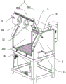
FIG. 1 is an isometric view of a sealed sander door of the present invention open;
FIG. 2 is an enlarged view of a portion of FIG. 1 at A;
FIG. 3 is an isometric view of a sealed sander door of the present invention closed;
FIG. 4 is a front view of a sealed sander door of the present invention closed;
FIG. 5 is a partial cross-sectional view taken at B-B of FIG. 4;
fig. 6 is a partially enlarged view at C in fig. 5.
In the figure: 1. a body; 101. opening the side; 2. a machine door; 201. a first door; 202. a second door; 3. a first baffle plate; 4. an annular air bag; 5. a second baffle; 6. sealing the space; 7. a containing groove; 8. a seal member; 9. Pulling a rope; 10. a through hole; 11. a spring; 12. mounting blocks; 13. a lift arm; 14. a nitrogen spring; 15. locking; 16. a buckle clamp; 17. a pull ring; 18. and a gas passing channel.
Detailed Description
The technical solution in the embodiments of the present invention will be clearly and completely described below with reference to the accompanying drawings in the embodiments of the present invention.
Examples
A sealed sand blasting machine, refer to fig. 1 to 6, including the organism 1 with side opening 101 and upside-down set up in the side opening 101 in order to open or close the door 2 of the side opening 101, the door 2 includes the first door 201 hinged with upper end of the side opening 101 and the second door 202 hinged with lower end of the first door 201, there are sealing mechanisms between door 2 and organism 1, the sealing mechanism includes the first blind 3 that extends and sets up outwards vertically around the circumference of the side opening 101 on the outer wall of the organism 1, the annular gasbag 4 that is set up fixedly on the sidewall of the first blind 3 and the second blind 5 that extends and sets up vertically around the circumference of the side opening 101 to the direction close to organism 1 on the inner wall of the door 2, there is sealed space 6 for the annular gasbag 4 to expand between first blind 3 and the second blind 5, the inflation or deflation of the annular gasbag 4 is controlled by a control mechanism, the control mechanism comprises a containing groove 7 which is communicated with the annular air bag 4 in the machine body 1 and a sealing element 8 which is in sealed activity in the containing groove 7 and can be far away from the annular air bag 4 to inflate or be close to the annular air bag 4 to deflate, the containing groove 7 and the annular air bag 4 are communicated through an air passage 18 which is arranged in the machine body 1, the sealing element 8 is close to or far away from the annular air bag 4 and is controlled by a driving mechanism, the driving mechanism comprises a drawing mechanism which drives the sealing element 8 to be close to the annular air bag 4 and a resetting mechanism which drives the sealing element 8 to be far away from the annular air bag 4, the drawing mechanism comprises a pull rope 9 of which two ends are respectively and fixedly connected with one side of the sealing element 8 close to the annular air bag 4 and the inner wall of the first door 201, one side of the containing groove 7 close to the annular air bag 4 is provided with a through hole 10 which is communicated with the outside of the machine body 1 and is used for the pull rope 9 to pass through, the resetting mechanism comprises a spring 11 which is fixedly arranged between one side of the containing groove 7 close to or far away from the annular air bag 4 and the sealing element 8, at least one spring 11 is uniformly arranged between the accommodating groove 7 and the sealing piece 8 at intervals.
The self-opening mechanism for driving the machine door 2 to be upturned and keeping the upturned state is arranged between the machine door 2 and the machine body 1 and comprises an installation block 12 extending horizontally from the second door 202 to the machine body 1, a lifting arm 13 with one end hinged to the installation block 12 and the other end hinged to the machine body 1 and a nitrogen spring 14 driving the lifting arm 13 to lift the machine door 2 upwards, one end of the nitrogen spring 14 is hinged to the side wall of the machine body 1, the other end of the nitrogen spring is hinged to one end, close to the lifting arm 13 and hinged to the machine body 1, of the lifting arm 13, a locking mechanism for preventing the machine door 2 from being opened automatically is arranged between the lower end of the second door 202 and the machine body 1 and is a door buckle type clamp which comprises a lock catch 15 fixed on the second door 202 and a clamp 16 fixed on the machine body 1, and a pull ring 17 convenient for pulling down the second door 202 is arranged on the outer wall of the lower end of the second door 202.
When the machine door 2 needs to be opened, the locking mechanism is unlocked, the nitrogen spring 14 resets and extends to drive the lifting arm 13 to turn upwards, at the moment, the first door 201 turns upwards, the pull rope 9 fixedly connected with the inner wall of the first door 201 is pulled out along with the upward turning, the sealing element 8 moves towards the direction close to the annular air bag 4 under the pulling action of the pull rope 9, the annular air bag 4 is deflated and contracted, the second baffle 5 is not in contact with the annular air bag 4 in the upward turning process, the abrasion of the annular air bag 4 is reduced, the lifting arm 13 is limited in length, the second door 202 is driven to turn downwards relative to the first door 201, the first door 201 and the second door 202 are folded, the occupied space of the machine door 2 is reduced after the machine door 2 is opened, and the feeding is convenient and the operator can close the machine door 2; when door 2 need be closed, pulling ring 17 downwards, door 2 overturns downwards gradually, pulling force on the sealing member 8 disappears gradually, sealing member 8 moves to the direction of keeping away from annular gasbag 4 under the spring 11 elastic force effect, make the gas sealed in sealing member 8 and storage tank 7 receive extrusion entering annular gasbag 4, annular gasbag 4 inflates the inflation, when door 2 closes completely, the atmospheric pressure balance in spring 11 elasticity and the annular gasbag 4, annular gasbag 4 expands to 5 elastic butt with the second baffle, with the locking mechanism locking, nitrogen spring 14 is in the contraction state all the time under the effect of locking force.
Finally, it should be noted that: although the present invention has been described in detail with reference to the foregoing embodiments, it will be apparent to those skilled in the art that changes may be made in the embodiments and/or equivalents thereof without departing from the spirit and scope of the utility model. Any modification, equivalent replacement, or improvement made within the spirit and principle of the present invention should be included in the protection scope of the present invention.
Claims (10)
1. The utility model provides a sealed sand blasting machine, includes organism (1) that has side opening (101) and upside-down upset setting in order to open or close quick-witted door (2) of side opening (101) on side opening (101), is provided with sealing mechanism, its characterized in that between quick-witted door (2) and organism (1): sealing mechanism includes on organism (1) outer wall around first baffle (3) that side opening (101) circumference outside perpendicular extension set up, fixed annular gasbag (4) that set up on first baffle (3) lateral wall and on door (2) inner wall around side opening (101) circumference to the perpendicular second baffle (5) that extend the setting of direction that is close to organism (1), there is sealed space (6) that supply annular gasbag (4) inflation between second baffle (5) and first baffle (3), the inflation or the gassing of annular gasbag (4) are controlled by a control mechanism.
2. A seal-type blasting machine according to claim 1, wherein: the control mechanism comprises a containing groove (7) which is communicated with the annular air bag (4) in the machine body (1) and a sealing element (8) which is in sealing movement in the containing groove (7) and can be far away from the annular air bag (4) to inflate or be close to the annular air bag (4) to deflate, and the sealing element (8) is controlled by a driving mechanism to be close to or far away from the annular air bag (4).
3. A seal sander according to claim 2, wherein: the driving mechanism comprises a traction mechanism for driving the sealing element (8) to be close to the annular air bag (4) and a reset mechanism for driving the sealing element (8) to be far away from the annular air bag (4).
4. A seal sander according to claim 3, wherein: the traction mechanism comprises a pull rope (9) with two ends fixedly connected with one side, close to the annular air bag (4), of the sealing element (8) and the inner wall of the machine door (2), and a through hole (10) communicated with the outside of the machine body (1) and used for the pull rope (9) to pass through is formed in one side, close to the annular air bag (4), of the accommodating groove (7).
5. A seal sander according to claim 3, wherein: the reset mechanism comprises a spring (11) which is fixedly arranged between one side of the containing groove (7) close to or far away from the annular air bag (4) and the sealing element (8).
6. A seal sander according to claim 5, wherein: at least one spring (11) is uniformly arranged between the accommodating groove (7) and the sealing element (8) at intervals.
7. A seal-type blasting machine according to claim 1, wherein: be provided with between quick-witted door (2) and organism (1) and order about quick-witted door (2) and turn over and keep turning over the self-opening mechanism of state on the top, self-opening mechanism includes from quick-witted door (2) to organism (1) horizontally extending's installation piece (12), one end and installation piece (12) articulated and the other end and organism (1) articulated lifting arm (13) and order about lifting arm (13) upwards to lift nitrogen gas spring (14) of quick-witted door (2), the one end and the organism (1) lateral wall of nitrogen gas spring (14) are articulated, and its other end and lifting arm (13) are close to its one end articulated with organism (1), be provided with the locking mechanism who avoids quick-witted door (2) automatic opening between quick-witted door (2) lower extreme and organism (1).
8. A seal sander according to claim 7, wherein: the machine door (2) comprises a first door (201) hinged to the upper end of the side opening (101) and a second door (202) hinged to the lower end of the first door (201), the locking mechanism is arranged between the second door (202) and the machine body (1), and the mounting block (12) is far away from one end hinged to the lifting arm (13) and is fixed to the second door (202).
9. A seal sander according to claim 8, wherein: the locking mechanism is a door buckle type clamp, and the door buckle type clamp comprises a lock catch (15) fixed on the second door (202) and a clamping clamp (16) fixed on the machine body (1).
10. A seal sander according to claim 8, wherein: and a pull ring (17) convenient for pulling down the second door (202) is arranged on the outer wall of the lower end of the second door (202).
Priority Applications (1)
| Application Number | Priority Date | Filing Date | Title |
|---|---|---|---|
| CN202121020972.9U CN215510601U (en) | 2021-05-13 | 2021-05-13 | Sealed sand blasting machine |
Applications Claiming Priority (1)
| Application Number | Priority Date | Filing Date | Title |
|---|---|---|---|
| CN202121020972.9U CN215510601U (en) | 2021-05-13 | 2021-05-13 | Sealed sand blasting machine |
Publications (1)
| Publication Number | Publication Date |
|---|---|
| CN215510601U true CN215510601U (en) | 2022-01-14 |
Family
ID=79804151
Family Applications (1)
| Application Number | Title | Priority Date | Filing Date |
|---|---|---|---|
| CN202121020972.9U Active CN215510601U (en) | 2021-05-13 | 2021-05-13 | Sealed sand blasting machine |
Country Status (1)
| Country | Link |
|---|---|
| CN (1) | CN215510601U (en) |
-
2021
- 2021-05-13 CN CN202121020972.9U patent/CN215510601U/en active Active
Similar Documents
| Publication | Publication Date | Title |
|---|---|---|
| EP1541255B1 (en) | A means of gripping for gripping and lifting an object | |
| US4821468A (en) | Dock seal | |
| US10023037B2 (en) | Vacuum blocker | |
| CA2916435C (en) | Weather barrier apparatuses for sealing or sheltering vehicles at loading docks | |
| CN116624443B (en) | Energy accumulator leather bag assembly and energy accumulator | |
| CN215510601U (en) | Sealed sand blasting machine | |
| US20170247207A1 (en) | Inflatable seal for door openings | |
| US5109639A (en) | Dock seal | |
| US7056109B2 (en) | Tire vulcanizing device | |
| CN109339641B (en) | Sealing door | |
| US5791532A (en) | Process for reversing and end-shaping inflatable bodies | |
| CN113976756A (en) | Automobile panel stamping die's pull-back mechanism | |
| EP1953099A1 (en) | Inflatable shelter | |
| EP3403955B1 (en) | Bottom seal assembly for dock ramp | |
| CN113002606A (en) | Consumable retail transportation device | |
| CN117124574A (en) | A long-life unloading rack for take-out box production | |
| CN214365669U (en) | Quick opening and closing door | |
| CN212304249U (en) | Self-locking type inflating cabinet | |
| GB2273960A (en) | Inflatable tube for sealing or actuating | |
| CN113236092A (en) | Zipper door with high sealing performance | |
| US6910733B2 (en) | Resilient wind deflector | |
| CN223311136U (en) | Cleaning device | |
| CN222921460U (en) | Grease recovery vehicle | |
| JP3083036U (en) | Dock shelter | |
| CN118293120B (en) | Quick lifting valve and lifting seat |
Legal Events
| Date | Code | Title | Description |
|---|---|---|---|
| GR01 | Patent grant | ||
| GR01 | Patent grant |