Detailed Description
Reference will now be made in detail to embodiments of the present invention, examples of which are illustrated in the accompanying drawings, wherein like or similar reference numerals refer to the same or similar elements or elements having the same or similar function throughout. The embodiments described below with reference to the accompanying drawings are illustrative only for the purpose of explaining the present invention, and are not to be construed as limiting the present invention.
The common food processer in the related art generally comprises a base assembly and a pot body assembly, wherein a power supply, a circuit board and a motor are arranged in the base assembly, and a heating plate is arranged in the pot body assembly. The base assembly extends out a transmission shaft to be matched with the pot body assembly to drive the cutter in the pot body assembly to rotate, so that the functions of crushing and stirring food materials are realized. The heating plate heats the pot body and transfers the heat to the bottom of the pot body.
However, the prior art has the following problems: firstly, the cutter of the existing food processor and the wall breaking machine cannot be disassembled, the connecting part of the cutter and the bottom has dead angles, and the cleaning is more difficult under the bottom pasting condition; secondly, the existing cooking mechanism is easy to be burnt; thirdly, the surface temperature is high, and the scald is easy to occur.
In order to solve the current problems, the invention provides a cooking appliance 100, wherein the cooking appliance 100 can be a household sauce manufacturing furnace or a sauce making machine and the like, and has the characteristics of stable temperature, easy disassembly and cleaning of a cutter, safety and scald prevention and the like.
A cooking appliance 100 according to an embodiment of the present invention is described below with reference to the accompanying drawings.
The cooking appliance 100 according to the embodiment of the first aspect of the present invention includes: the pot body assembly comprises a machine body 1, a pot body assembly 2, a cutter assembly 3 and a cover body assembly 4.
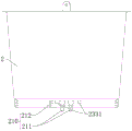
Specifically, the machine body 1 is provided with a first connector 110, the first connector 110 may be disposed in the machine body 1, and the first connector 110 may be disposed at the bottom of the machine body 1, and the machine body 1 defines the accommodating cavity 10 therein. The accommodation chamber 10 facilitates the placement of other components of the cooking appliance 100. The holding cavity 10 is a sheet metal part, a flanging is arranged on the sheet metal part, and the holding cavity 10 is connected with a shell screw of the machine body 1 through the flanging.
The pan body assembly 2 comprises: an outer pot body 21 and an inner pot body 22. Specifically, the outer pot 21 is disposed in the accommodating cavity 10, and the outer pot 21 can be connected with a second connector 210, and the second connector 210 is electrically connected with the first connector 110.
An accommodating space 23 is defined between the inner layer pan body 22 and the outer layer pan body 21, a heat conducting medium and a heating element 232 are arranged in the accommodating space 23, and the heating element 232 is connected with the second connector 210. The heat conducting medium can be heat conducting oil or molten salt and the like. The heating member 232 in the present application may be at least one of a heating tube, a heating sheet and a heating surface. Like this when first connector 110 external power source, because first connector 110 is connected with second connector 210 electricity, can make like this and generate heat a 232 production of heat, thereby can be right heat-conducting medium heats, and heat-conducting medium and inlayer pot body 22 heat transfer are with the edible material in the heating inlayer pot body 22, and can heat diapire and the perisporium of inlayer pot body 22 simultaneously, compare in the heating mode that adopts the heating plate, this application carries out the scheme that heats through heat-conducting medium indirect edible material in the inlayer pot body 22, be favorable to guaranteeing the homogeneity of heating, improve and stick with paste the end phenomenon.
The present application mainly uses a heat conducting medium as a heat conducting oil for illustration, however, this should not be construed as a limitation to the present invention. In some embodiments of the present invention, the heat conducting medium may also be a molten salt, and the present invention does not specifically limit the specific selection of the heat conducting medium, and the heat conducting medium may be adaptively selected according to the needs in practical applications.
A positioning shaft 20 is formed on the inner bottom surface of the inner layer pot body 22; the cutter member 3 is formed with a positioning hole 30 that matches the positioning shaft 20. Referring to fig. 1 and 10, in some embodiments, the positioning shaft 20 extends upward, the cutter assembly 3 is provided with a positioning hole 30, and the positioning hole 30 is matched with the positioning shaft 20, so that the cutter assembly 3 can be positioned in the cup body 2 by matching the positioning hole 30 with the positioning shaft 20, fixing and limiting of the cutter assembly 3 are achieved, positioning is accurate, and coaxiality is guaranteed.
The cover body assembly 4 is covered on the machine body 1, a through hole 40 communicated with the inner layer pot body 22 is formed on the cover body assembly 4, and the cover body assembly 4 comprises a driving motor 41 connected with the cutter assembly 3.
Through-hole 40 can be the array and arrange, and through-hole 40 and the inner chamber intercommunication of inlayer pot body 22, lid subassembly 4 includes driving motor 41, and driving motor 41 links to each other with the transmission of cutter unit 3, can drive cutter unit 3 through driving motor 41 and rotate to the realization is to eating the stirring of material and turning in the inlayer pot body 22, and moisture in the food can be discharged through-hole 40.
In some embodiments, the cover assembly 4 includes a cover body having a through hole formed therein for communicating with the inner pot 22, and a driving motor 41 connected to the cutter assembly 3 and the driving motor 41.
Wherein, can heat the high temperature heat-conducting medium in accommodation space 23 through piece 232 that generates heat, heat-conducting medium 231 takes place natural convection after being heated, with heat transfer to the inlayer pot body 22, food is transferred with the heat to the rethread inlayer pot body 22, and driving motor 41 can also drive cutter unit 3 low-speed stirring food simultaneously for food is heated more evenly, and the heating homogeneity effect is better.
According to the cooking appliance 100 of the embodiment of the invention, the heat-conducting medium in the accommodating space 23 can be heated by the heating member 232, natural convection occurs after the heat-conducting medium is heated, the heat is transferred to the inner pot 22, and then the heat is transferred to food by the inner pot 22, meanwhile, the driving motor 41 can drive the cutter assembly 3 to stir the food at a low speed, so that the food is heated more uniformly, the heating uniformity effect is better, and the technical problems that the food material is heated non-uniformly and is easy to stick to the bottom in the related art can be solved.
Referring to fig. 2 and 4, according to some embodiments of the present invention, the first connector 110 includes a socket body 111, and the second connector 210 includes electrical terminals 211, the electrical terminals 211 being electrically connected with the socket body 111. By electrically connecting the electric terminals 211 to the socket body 111, the heating member 232 can be heated, and the heat transfer medium can be heated, thereby further heating the food material in the inner pot 22.
Further, referring to fig. 3 and 4, the first connector 110 further includes a micro switch 112, the micro switch 112 is disposed in the socket body 111, and the second connector 210 further includes a trigger 212, and the trigger 212 is configured to trigger the micro switch 112. When the pot body assembly 2 is placed in the accommodating cavity 10, the electric connection terminal 211 is electrically connected with the socket body 111, and the trigger part 212 is convenient for triggering the micro switch 112, so that the corresponding control of heating food materials in the inner pot body 22 can be better realized.
Referring to fig. 2, 3 and 5, in some embodiments of the invention, the socket body 111 is provided with a through hole 1111 and a plug hole 1112, the micro switch 112 includes a micro switch body 1121 and a spring piece 1122, and the touching portion 212 is adapted to touch the spring piece 1122 through the through hole 1111 to trigger the micro switch 112. Thus, when the pot body assembly 2 is placed in the accommodating cavity 10, the electrical connection terminal 211 is electrically connected with the socket body 111 through the electrical insertion hole 1112, and the touch part 212 can pass through the through hole 1111 to touch the elastic sheet 1122, so that the micro switch 112 can be triggered, and the micro switch 112 works; when the pan body assembly 2 is taken out, the electric connection terminal 211 is disconnected from the socket body 111, and the touching portion 212 releases the elastic sheet 1122, so that the micro switch 112 can be reset.
The microswitch is a switch having a minute contact interval and a snap action mechanism, which performs a switching operation with a predetermined stroke and a predetermined force, covered with a case, and having a drive lever outside thereof, and is called a sensitive switch because the contact pitch of the switch is relatively small.
Referring to fig. 1 and 6, according to some embodiments of the present invention, the heating element 232 is adapted to be connected to the outer pot 21 through a heating element flange 233, the heating element flange 233 and the outer pot 21 can be connected by screws, the heating element flange 233 can be provided with a touch portion 212, and in some embodiments, the touch portion 212 is configured as a thimble structure provided on the heating element flange 233, but the present invention is not limited thereto.
In some embodiments, referring to fig. 2 and 6, a flange screw 2331 extending downward may be formed on the heat generating member flange 233, and a screw hole 1113 may be formed on the socket body 111 of the first connector 110, so that the flange screw 2331 is screwed into the screw hole 1113, thereby achieving the assembling connection between the pot assembly (outer pot 21) and the first connector 110.
Further, referring to fig. 1, a sealing member 234 (such as a sealing washer) is disposed between the inner surface of the outer pot 21 and the heating member flange 233. The sealing element 234 is convenient for realizing the sealing connection between the outer pot body 21 and the heating element flange 233, and is beneficial to ensuring the use reliability of the cooking appliance 100.
According to some embodiments of the invention, the inner bottom surface of the containing cavity 10 is formed with a positioning part, and the outer pot 21 is suitable for being positioned by the positioning part.
In some embodiments, the inner bottom surface of the accommodating cavity 10 is formed with a positioning step portion, and the outer pot body 21 is suitable for being positioned by the positioning step portion. When the pot body assembly 2 is placed in the accommodating cavity 10, the outer layer pot body 21 can be positioned through the positioning step part.
In some embodiments, a positioning protrusion may be disposed on the inner bottom surface of the accommodating cavity 10, and a positioning groove matched with the positioning protrusion is formed on the outer bottom surface of the outer pot body 21, so that the positioning of the pot body assembly 2 in the accommodating cavity 10 can also be realized through the matching of the positioning protrusion and the positioning groove.
Of course, in some embodiments, the positioning of pan body assembly 2 inside accommodation chamber 10 can also be achieved directly by the electrical connection of first connector 110 and second connector 210.
According to the cooking utensil 100 of the embodiment of the invention, the heating element 232 (such as a heating tube and the like) is matched with the outer pot body 21 through the sealing element 234 and the heating tube flange 233 to realize sealing. The containing space 23 is filled with heat conduction oil, the heating tube heats the heat conduction oil after being electrified, and the heat conduction oil naturally convects to heat the inner pot body 22 and heat and concentrate food.
The pot body assembly 2 is matched with the bottom wall of the accommodating cavity 10, and the pot body assembly 2 is limited through the positioning part. A first connector 110 (plug socket) is disposed in the machine body 1, the first connector 110 includes a socket body 111 and a micro switch 112, a via hole 1111 and a plug hole 1112 are disposed on the socket body 111, and the micro switch 112 is used for controlling on/off of a circuit. Thus, when the pot body assembly 2 is placed in the accommodating cavity 10, the electrical connection terminal 211 is electrically connected with the socket body 111 through the electrical insertion hole 1112, and the touch part 212 can pass through the through hole 1111 to touch the elastic sheet 1122, so that the micro switch 112 can be triggered, and the micro switch 112 works.
In some embodiments, the outer pot 21 and the inner pot 22 may be sheet metal parts, and they may be hermetically connected by welding.
In some embodiments, the inner pot 22 may also be a high borosilicate glass material or a 304 stainless steel material. Borosilicate glass is a glass that enhances fire resistance. The high borosilicate glass has good fire resistance and high physical strength, and compared with common glass, the high borosilicate glass has no toxic or side effect, and the mechanical property, the thermal stability, the water resistance, the alkali resistance, the acid resistance and other properties are greatly improved.
In some embodiments, the machine body 1 includes a casing and a liner, the casing is connected with the liner by screws, the inner portion of the liner can define the accommodating cavity 10, the casing includes an upper casing 101 and a lower casing 102 (refer to fig. 1), the upper casing 101 is connected with the liner, and a support (not shown in the figure) is further disposed in the machine body 1, and the support is respectively connected with the upper casing 101 and the lower casing 102 by screws.
In some embodiments of the present invention, the inner pot 22 is closed at the bottom and open at the top, the inner pot 22 comprises a bottom wall and a peripheral wall, a circular arc transition part is formed between the bottom wall and the peripheral wall, and at least part of the bottom wall is configured to be convex towards the inner pot 22.
In some embodiments of the present invention, the outer pot body 21 can be made of a high-reflectivity material, so that the heat penetration rate can be reduced, and the heat reflectivity can be improved, thereby facilitating the improvement of the energy utilization rate and the heating efficiency.
However, the present invention is not limited thereto, and in some embodiments, the inner surface of the outer pot 21 may be provided with a high-reflectivity coating (e.g., a mirror aluminum coating, a mirror silver coating, etc.). Therefore, the high-reflectivity coating can reduce the heat penetration rate and improve the heat reflectivity, thereby being beneficial to improving the energy utilization rate and improving the heating efficiency.
In some embodiments of the present invention, referring to fig. 7 and 8, the cutter member 3 includes a rotating shaft 31 and a plurality of blades 32, the bottom of the rotating shaft 31 is provided with the positioning hole 30, and the plurality of blades 32 are arranged in parallel and spaced apart outside the rotating shaft 31. In some embodiments, the cutting edge 32 is disposed obliquely downward relative to the plane of the axis of rotation 31. The cutter assembly 3 can realize pushing food to rotate around the rotating shaft 31 when rotating at a low speed, so that the stirring effect is realized, and the dual functions of crushing and stirring are realized.
According to the cooking utensil 100 of the embodiment of the invention, in the process of stirring food by rotating the cutter assembly 3, the cutting edge 32 can shear the food, so that the food is continuously deformed, and the sheared food is relatively moved, so that the food in a fluid state is more strongly rolled, and therefore, the heat convection effect can be improved, the heating uniformity is ensured, and the bottom burnt is prevented.
In some embodiments, referring to fig. 7 and 8, the blade 32 may be configured in an arc shape extending around the rotating shaft 31, the width of the blade 32 decreases from a fixed end to a free end, the fixed end of the blade 32 may refer to the end of the blade 32 connected to the rotating shaft 31, and the outer end of the blade 32 may be chamfered, so that the blade 32 is sharper and more beneficial to crush the food material.
In some embodiments, referring to fig. 9, the width of the blade 32 in the direction of its extension may also be constant.
In some embodiments of the present invention, the motor shaft 411 of the drive motor 41 is removably connected to the cutter assembly 3. The first motor shaft 411 extends downward, and further, referring to fig. 1, the cutter assembly 3 is spline-connected to the first motor shaft 411. Like this through making cutter unit 3 and first motor shaft 411 splined connection for whole cutter unit 3 can directly be pulled out, convenient to detach, and the washing of the cutter unit 3 of being convenient for.
In some embodiments, the top of the rotating shaft 31 is provided with a spline shaft, and the first motor shaft 411 is formed with a spline groove matching with the spline shaft. In some embodiments, the rotating shaft 31 includes a rotating shaft body, the spline shaft being formed at the top of the rotating shaft body, and a connecting portion through which the plurality of blades 32 are connected to the rotating shaft 31. The blade 32 and the connecting portion may be connected by a screw.
In some embodiments of the present invention, the cutter assembly 3 may be an integrated structure, and referring to fig. 8, the cutting edge 32 may be first placed in a mold, and then the cutter assembly 3 is formed by integrally forming in the mold, at this time, the cutter assembly 3 is an integrated structure.
The invention is not limited thereto, and in some embodiments, referring to fig. 7, the cutter assembly 3 may be a split structure, and the cutting edge 32 and the rotating shaft 31 may be connected by means of a screw connection.
The cutter assembly 3 in the invention can be quickly disassembled and replaced. Therefore, in addition to using the crushing and stirring two-in-one functional cutter assembly 3 of the present invention, it is also possible to use a stirring blade as shown in fig. 9 instead of a cutter after the crushing is completed, thereby realizing the stirring function required in the cooking, concentration and sauce making processes.
Referring to fig. 9, in some embodiments of the present invention, the blade 32 may be formed with a plurality of through holes 321, and the plurality of through holes 321 are spaced apart in a length direction of the blade 32. By providing the through hole 321, the disturbance of the fluid in the cup body 2 is made stronger, and the heat convection effect can be further improved.
According to the cutter assembly 3 of the embodiment of the invention, the cutter assembly 3 comprises a rotating shaft 31 and a plurality of blades 32, the bottom of the rotating shaft 31 is provided with a positioning hole 30, the blades 32 are arranged in parallel and at intervals outside the rotating shaft 31, and the top of the rotating shaft 31 is provided with a spline shaft.
According to the cooking utensil 100 provided by the embodiment of the invention, the cutter assembly 3 and the driving motor 41 are connected through the key slot, so that the cutter assembly can be quickly separated and is convenient to clean. Meanwhile, high temperature heat-conducting medium 231 in accommodation space 23 can be heated through heating element 232, natural convection takes place after heat-conducting medium 231 is heated, with heat transfer to inlayer pot body 22, food is transferred with heat to rethread inlayer pot body 22, meanwhile driving motor 41 can also drive 3 low-speed stirring food of cutter subassembly for food is heated more evenly, and heating homogeneity effect is better, has characteristics such as temperature stability, the easy dismouting of cutter is easily cleaned.
According to the cooking utensil 100 provided by the embodiment of the invention, the cutter can be quickly detached and replaced, and the cup body and the cutter are convenient to clean. By adopting the oil bath heating scheme, after the heat conduction oil is heated, the temperature uniformity is good, so that the food materials can be uniformly heated.
In some embodiments of the present invention, referring to fig. 11, the positioning shaft 20 is further sleeved with a support 6, and the lower end face of the rotating shaft 31 of the cutter assembly 3 is supported on the support 6. The lower end surface of the rotation shaft 31 may be spaced apart from the inner bottom surface of the cup body 2 by a support member 6, and in some embodiments, the support member 6 may be a support pad or the like. The upper end of cutter unit 3 links to each other with first motor shaft 531, and the lower extreme of cutter unit 3 links to each other with rotation axis 31 and supports through support piece 6, can all fix the upper and lower both ends of cutter unit 3 like this, is favorable to reducing the axial runout of cutter unit 3 in rotatory in-process.
Further, in connection with fig. 11, the projection of the support 6 onto the plane of the rotation axis 31 is located inside the projection of the rotation axis 31. The projection of the support 6 is located inside the projection of the rotation axis 31 in the plane of the rotation axis 31, and in some embodiments the area of the support 6 is no greater than the cross-sectional area of the rotation axis 31. Therefore, the cutter assembly 3 can be lifted through the support piece 6, and compared with the situation that the rotating shaft 31 is directly contacted with the inner bottom surface of the cup body 2, the contact area can be reduced, the friction force is reduced, and the power loss is reduced.
According to the cooking utensil 100 of the embodiment of the invention, the rotating shaft 31 of the whole cutter assembly 3 can be lifted through the support 6, the jump of the cutter assembly 3 in the axial direction during the rotation process can be reduced by fixing the upper end and the lower end of the rotating shaft 31, the contact area of the support 6 and the contact surface of the rotating shaft 31 can be reduced by limiting the size relation of the area of the support and the contact surface of the rotating shaft, the contact friction is reduced, and the power loss is reduced.
In some embodiments, the inner wall of the inner pot 22 may also be provided with turbulence ribs. The turbulence ribs can comprise one or more ribs, and the turbulence ribs can be arc-shaped or linear and the like. The turbulence ribs are favorable for realizing the disturbance of food materials, so that the uniformity of heating can be ensured, and bottom pasting and the like are prevented.
In some embodiments of the present invention, an electric control board may be disposed in the cover assembly 4, and the electric control board includes a motor speed regulation control board and a power board, so that the rotation speed of the driving motor 41 can be adjusted, and the food material can be stirred and turned at the actually required rotation speed.
In some embodiments of the invention, the cover assembly 4 includes a motor mount on which the drive motor 41 is supported. In some embodiments, a driving gear set is further disposed in the cover assembly 4, and the driving gear set is in transmission connection with the driving motor 41. The specific form of the specific driving gear set is not limited, and the driving gear set is preferably arranged to effectively drive the cutter assembly 3 to rotate so as to stir and turn the food materials.
According to the cooking apparatus 100 of the embodiment of the present invention, the lid assembly 4 contains a motor assembly (including the driving motor 41), a concentrated vent array (through holes), a top cover fixing plate, a silicone member, and the like. During the use, will place cutter unit spare 3 in pot body subassembly 2 earlier, realize the fixed of cutter and spacing through ejecting protruding package (location axle 20) in the inlayer pot body 22, will make sauce raw materials such as fruit, meat place in the inlayer pot body 22 again, cover lid subassembly 4 at last on the inlayer pot body 22, be connected top cap and cutter unit spare 3 through the keyway to realize the transmission.
Through the intraformational conduction oil of heating tube heating oil bath intermediate layer in the pot body subassembly 2, with heat transfer to the inlayer pot body 22 through the conduction oil, the food of the internal heat transfer of rethread inlayer pot body 22 with the heat transfer, realize culinary art function, heat food and concentration, moisture in the food, the vapor that produces among the heating process pass through the through-hole and discharge.
According to the cooking utensil 100 of the embodiment of the invention, compared with the traditional food processor with the sauce making function, the following advantages are provided: firstly, the cutter can be quickly detached and replaced, and the pot body assembly 2 and the cutter are convenient to clean. Secondly, after the sauce making process is finished, only the pot body assembly 2 needs to be taken out, and the pot body assembly 2 has no other accessories except sauce materials, so that the sauce making machine is small, exquisite and lighter in weight. Thirdly, adopt the heat-conducting medium heating, compare with traditional heating plate, the heat-conducting medium can heat pot body subassembly 2's bottom, can also heat around pot body subassembly 2, and its heating homogeneity is better, is more difficult to stick with paste the end.
Other constructions and operations of the cooking appliance 100 and the cutter assembly 3 according to the embodiment of the present invention are known to those skilled in the art and will not be described in detail herein.
In the description of the present invention, it is to be understood that the terms "central," "longitudinal," "lateral," "length," "width," "thickness," "upper," "lower," "front," "rear," "left," "right," "vertical," "horizontal," "top," "bottom," "inner," "outer," "clockwise," "counterclockwise," "axial," "radial," "circumferential," and the like are used in the orientations and positional relationships indicated in the drawings for convenience in describing the invention and to simplify the description, and are not intended to indicate or imply that the referenced device or element must have a particular orientation, be constructed and operated in a particular orientation, and are not to be considered limiting of the invention.
In the description of the present invention, "the first feature" and "the second feature" may include one or more of the features. In the description of the present invention, "a plurality" means two or more. In the description of the present invention, the first feature being "on" or "under" the second feature may include the first and second features being in direct contact, and may also include the first and second features being in contact with each other not directly but through another feature therebetween. In the description of the invention, "above", "over" and "above" a first feature in a second feature includes the first feature being directly above and obliquely above the second feature, or simply means that the first feature is higher in level than the second feature.
In the description herein, references to the description of the term "one embodiment," "some embodiments," "an illustrative embodiment," "an example," "a specific example," or "some examples" or the like mean that a particular feature, structure, material, or characteristic described in connection with the embodiment or example is included in at least one embodiment or example of the invention. In this specification, the schematic representations of the terms used above do not necessarily refer to the same embodiment or example. Furthermore, the particular features, structures, materials, or characteristics described may be combined in any suitable manner in any one or more embodiments or examples.
While embodiments of the invention have been shown and described, it will be understood by those of ordinary skill in the art that: various changes, modifications, substitutions and alterations can be made to the embodiments without departing from the principles and spirit of the invention, the scope of which is defined by the claims and their equivalents.