Automatic forming all-in-one machine for shielding component of electronic equipment
Technical Field
The utility model belongs to the processing field is found in the shielding, concretely relates to electronic equipment shielding component automatic molding all-in-one.
Background
The shielding component of the electronic equipment is mainly used for inhibiting electromagnetic field induction interference existing between circuit units of the electronic equipment and between the electronic equipment, such as communication electronic products like mobile phones and the like, and core components need to be protected. For some sensitive circuits and devices inside electronic equipment, in order to reduce the influence of electromagnetic interference, a shielding sheet or a shielding case is often used to independently shield the sensitive circuits and the devices or the interference source circuits.
A common shielding member is a metal sheet with an insulating film attached thereon, and at present, the production mainly includes the following steps:
1. cutting the insulating film by adopting a professional die cutting machine;
2. machining a metal element on a stamping press;
3. manually adhering the insulating film to the corresponding position on the metal element.
The current processing method has the following problems:
1. the method has the advantages of multiple working procedures, mainly manual operation, more required personnel, low manual film pasting speed, high bubble reject ratio, high labor intensity and low production efficiency;
2. the processing process is carried out among a plurality of devices, the requirement on the workshop space is put forward, and a certain time is consumed in the carrying process;
3. the shielding component has high requirements on the position of the film, and workers with certain proficiency and professional ability are needed, so that the product quality is difficult to ensure manually.
SUMMERY OF THE UTILITY MODEL
The aforesaid that exists to prior art is not enough, the utility model discloses the processing method manual operation of the present shield member of technical problem who solves is main, and intensity of labour is big, is difficult to the accuse to product quality, and turnover process consumption time, occupies the workshop place.
In order to solve the technical problem, the utility model provides an automatic molding integrated machine for an electronic equipment shielding component, which comprises a machine body, a control button, an upper template, a lower template, an insulating film conveying assembly and a conveying belt,
a control button and a hydraulic oil cylinder are arranged on the machine body, the control button controls the punching of the upper template and the operation of the insulating film conveying component and the conveying belt, a piston cylinder of the hydraulic oil cylinder is connected with the upper template,
the middle part of the machine body is provided with a workbench, a lower template is arranged on the workbench, and a non-stick separation plate, a female die and a waste material port are arranged on the lower template; a notch is formed in the non-stick isolation plate, and the insulating film is adhered to the metal blank tape from the notch; the metal blank belt is conveyed to the lower template from the material storage disc and is punched at the female die, the waste material port is arranged at the rear part of the female die and collects the waste material of the metal blank belt left after punching,
the upper template is provided with a film cutter, a relief groove, a positioning punch and a male die, the film cutter is of a rectangular frame structure, an insulating film is cut out at one time by a cutter edge, a spherical film pressing block is arranged in a central cavity of the film cutter, and the spherical film pressing block is made of a flexible material and is extruded and deformed under pressure; the abdicating groove is larger than the formed insulating film, two rows of positioning punches which are uniformly distributed can punch positioning holes on the metal blank belt, the edge of the male die is provided with positioning needles which are matched with the positioning holes,
the insulating film conveying assembly stretches across the workbench and comprises a driver, an unwinding wheel, a winding wheel, a guide roller wheel and a one-way rotating wheel photoelectric sensor; the insulating film material belt is arranged on the unwinding wheel, the guide roller wheel and the winding wheel and is horizontally conveyed under the action of the driver, the photoelectric sensor of the unidirectional rotating wheel detects and ensures the conveying speed,
the conveyer belt is located the workstation side, sends fashioned shield member to finished product collection box.
Furthermore, a visual detector, a pneumatic push rod and a defective box are mounted on the machine body on the side face of the conveying belt for finished product blanking, the visual detector is used for photographing, analyzing and judging the shielding component, the pneumatic push rod is used for compensating the conveying speed, and unqualified products can be pushed into the defective box on the side face of the conveying belt under the action of the air cylinder.
Further, the control buttons comprise a power key, a start key and a stop key.
Further, the lower bolster is provided with a plurality of stoppers of evenly, the symmetry is arranged all around, and each stopper is column and equal height, and the stopper corresponds the breach cooperation with the bedplate board of cope match-plate pattern, leads and places the excessive pressure.
Furthermore, a spray gun is arranged between the lower template and the conveying belt, and the finished shielding component is blown to the conveying belt.
Further, the non-stick separator plate is coated with silicone oil.
The utility model has the advantages that:
the utility model discloses an electronic equipment shielding component automatic molding all-in-one adopts automatic operation, makes and cuts membrane, pad pasting, stamping forming and goes on simultaneously, accomplishes material loading, shaping and the combination of metal embryo area, insulating zone on an equipment, and the product uniformity is good, and the accurate nature in pad pasting position is high to detect and classify through visual detector. The production period is shortened, the occupied workshop space is reduced, the labor intensity of workers is reduced, the production efficiency is improved, and the product quality reliability is ensured.
Drawings
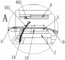
Fig. 1 is a schematic perspective view of the integrated machine for automatically forming shielding members of electronic equipment according to the present invention without an insulating film material tape;
fig. 2 is a schematic perspective view of the electronic device shielding member automatic molding integrated machine of the present invention with an insulating film material strip placed thereon;
FIG. 3 is an enlarged schematic view of portion A of FIG. 2;
fig. 4 is a schematic perspective view of the upper plate according to the present invention;
FIG. 5 is an enlarged schematic view of the film cutting knife and the spherical film pressing block of the present invention;
fig. 6 is a schematic top view of the metal blank of the present invention placed on the lower mold plate.
In the figure: 1. a body; 2. a material storage tray; 3. a metal green tape; 4. a control button; 5. a lower template; 501. non-stick insulation board; 502. a female die; 503. positioning holes; 504. a waste material port; 6. mounting a template; 601. a film cutter; 602. a yielding groove; 603. positioning the punch; 604. a male die; 605. a spherical surface film pressing block; 7. a work table; 8. an insulating film transfer member; 9. a conveyor belt; 10. a shielding member; 11. a defective cartridge; 12. a finished product collection box; 13. a vision detector; 14. an insulating film material band; 15. a limiting block; 16. and a pneumatic push rod.
Detailed Description
The following detailed description of the present invention will be made in conjunction with the accompanying drawings and specific embodiments.
As shown in FIG. 1, an automatic molding integrated machine for electronic device shielding components comprises a machine body 1, a control button 4, an upper template 6, a lower template 5, an insulating film conveying assembly 8 and a conveying belt 9,
a control button 4 and a hydraulic oil cylinder are installed on the machine body 1, the control button 4 controls the punching of the upper template 6 and the operation of the insulating film conveying component 8 and the conveying belt 9, and a piston cylinder of the hydraulic oil cylinder is connected with the upper template 6.
A workbench 7 is arranged in the middle of the machine body 1, as shown in fig. 6, a lower template 5 is mounted on the workbench 7, and a non-stick separation plate 501, a female die 502 and a waste opening 504 are arranged on the lower template 5; a notch is arranged on the non-stick isolation plate 501, and an insulating film is adhered to the metal green tape 3 from the notch; the metal blank 3 is conveyed from the storage tray 2 to the lower template 5 and is punched at the concave die 502, and the waste material port 504 is arranged at the rear part of the concave die 502 and collects the waste material of the metal blank 3 left after punching.
As shown in fig. 4, the upper die plate 6 is provided with a film cutter 601, a relief groove 602, a positioning punch 603, and a punch 604, wherein the film cutter 601 has a rectangular frame structure and cuts the insulating film at one time. The central cavity of the film cutting knife 601 is provided with a spherical film pressing block 605, as shown in fig. 5, the spherical film pressing block 605 is made of flexible material and is pressed, extruded and deformed; the receding groove 602 is larger than the formed insulating film, two rows of positioning punches 603 which are uniformly arranged can punch the positioning holes 503 on the metal green tape 3, and the edges of the punches 604 are provided with positioning pins which are matched with the positioning holes 503.
As shown in fig. 2 and 3, the insulating film conveying assembly 8 crosses the workbench 7 and comprises a driver, an unwinding wheel, a winding wheel, a guide roller wheel and a one-way rotating wheel photoelectric sensor; the insulating film material belt 14 is arranged on the unwinding wheel, the guide roller wheel and the winding wheel and is horizontally conveyed under the action of a driver, and the one-way rotating wheel photoelectric sensor detects and ensures the conveying speed.
The conveyor belt 9 is located at the side of the table 7 and feeds the shaped shielding elements 10 to a finished product collection box 12.
In practical application, a visual detector 13, a pneumatic push rod 16 and a defective box 11 are mounted on the machine body 1 on the side face of the conveying belt 9 for finished product blanking, the visual detector 13 is used for photographing, analyzing and judging the shielding component 10, the pneumatic push rod 16 is used for compensating the conveying speed, and unqualified products can be pushed into the defective box 11 on the side face of the conveying belt 9 under the action of an air cylinder.
In practical applications, the control buttons 4 include a power key, a start key, and a stop key.
In practical application, lower bolster 5 is provided with a plurality of stoppers 15 evenly, the symmetry is arranged all around, and each stopper 15 is column and equal height, and stopper 15 corresponds the breach cooperation with the bedplate board of cope match-plate pattern 6, leads and places the excessive pressure.
In practical application, a spray gun is arranged between the lower template 5 and the conveyer belt 9 to blow the finished shielding component 10 to the conveyer belt 9.
In practical applications, the non-stick separator plate 501 is coated with silicone oil.
The utility model discloses a theory of operation:
electronic equipment shielding member 10 automatic molding all-in-one, realize cutting of insulating film, paste with the stamping forming of metalwork, integrate three processes on an equipment, also can be alone to metalwork stamping forming when needs. The utility model discloses set up flexible sphere press mold piece 605 in cutting the sword, can reduce the bubble in the pad pasting after cutting, accomplish accurate pad pasting. The profiling silicone oil non-stick isolation plate 501 is added, so that the separation of redundant waste films and metal raw materials is facilitated. A fine adjustment mechanism is arranged at the position of the film cutting knife 601 to adjust the height of the opening of the film cutting knife 601; the linear speed of the insulating film material belt 14 is controlled by adopting the one-way rotating wheel photoelectric sensor, so that the waste of the insulating film material belt 14 is reduced. And an image detection system is additionally arranged to detect the quality of finished products and automatically eliminate unqualified products.
The utility model discloses a working process:
and (3) film cutting operation: when a starting button is pressed, the upper template 6 runs downwards from the highest point of the mould and carries the film cutting knife 601 to run, and when the upper template touches the supported and suspended insulating film material belt 14, the film cutting knife 601 presses the insulating raw material to continue to move downwards until the lowest point of the mould, and at the moment, the film cutting knife 601 just cuts through the insulating raw material.
Film pasting operation: the flexible spherical film pressing block 605 in the film cutting knife 601 uniformly presses the cut film on the metal raw material from the middle to the periphery, and the profiling silicone oil non-stick isolation plate 501 prevents the redundant waste film from being bonded with the metal raw material, thereby preventing the influence on conveying and damage to the insulating film material belt 14.
And (3) stamping operation: under the action of the positioning assembly, the punch and die 502 of the punch forming die upper template 6 and the lower template 5 complete the punching of metal parts to form the shielding component 10 with the insulating film, and the limiting block 15 prevents the overpressure.
Resetting operation: the upper template 6 moves upwards from the lowest point of the mold, the film cutting knife 601 does not press the insulating film any more, the waste film collecting wheel receives signals to operate at the moment, the insulating film material belt 14 is pulled, the one-way rotating wheel photoelectric sensor is driven to rotate for counting, when the counting is reached, the waste film collecting wheel stops operating, the insulating film is tensioned, supported and suspended, and the insulating film is accurately conveyed;
detection operation: the leveling conveyer belt 9 conveys the shielding component 10 pasted with the film forwards, and the mold reaches the highest point to complete one cycle; after several cycles, the electronic shielding component 10 with the film is conveyed out of the mold by the conveying belt, and the defective products are pushed into the defective product box after being photographed and detected by the vision detector 13, and the defective products flow into the defective product collecting box.
To sum up, the utility model discloses make and cut membrane, pad pasting, stamping forming and go on simultaneously, reduce production cycle, reduce workshop space and occupy, reduce workman intensity of labour, improve production efficiency, guarantee product quality reliability.
The foregoing illustrates and describes the principles, general features, and advantages of the present invention. It should be understood by those skilled in the art that the foregoing embodiments are merely illustrative of the technical concepts and features of the present invention, and the purpose of the present invention is to provide a person skilled in the art with the ability to understand the contents of the present invention and implement the same, and not to limit the scope of the present invention.