CN214625501U - Connector and connector assembly - Google Patents

Connector and connector assembly Download PDF

Info

Publication number
CN214625501U
CN214625501U CN202120566205.1U CN202120566205U CN214625501U CN 214625501 U CN214625501 U CN 214625501U CN 202120566205 U CN202120566205 U CN 202120566205U CN 214625501 U CN214625501 U CN 214625501U
Authority
CN
China
Prior art keywords
connector
housing
lock
guide
sliding plate
Prior art date
Legal status (The legal status is an assumption and is not a legal conclusion. Google has not performed a legal analysis and makes no representation as to the accuracy of the status listed.)
Active
Application number
CN202120566205.1U
Other languages
Chinese (zh)
Inventor
李健雄
杨昱辰
张萌羽
尹豪迈
Current Assignee (The listed assignees may be inaccurate. Google has not performed a legal analysis and makes no representation or warranty as to the accuracy of the list.)
Tyco Electronics Shanghai Co Ltd
Original Assignee
Tyco Electronics Shanghai Co Ltd
Priority date (The priority date is an assumption and is not a legal conclusion. Google has not performed a legal analysis and makes no representation as to the accuracy of the date listed.)
Filing date
Publication date
Application filed by Tyco Electronics Shanghai Co Ltd filed Critical Tyco Electronics Shanghai Co Ltd
Priority to CN202120566205.1U priority Critical patent/CN214625501U/en
Application granted granted Critical
Publication of CN214625501U publication Critical patent/CN214625501U/en
Priority to US17/696,205 priority patent/US12107366B2/en
Priority to DE102022106379.8A priority patent/DE102022106379A1/en
Active legal-status Critical Current
Anticipated expiration legal-status Critical

Links

Images

Classifications

    • HELECTRICITY
    • H01ELECTRIC ELEMENTS
    • H01RELECTRICALLY-CONDUCTIVE CONNECTIONS; STRUCTURAL ASSOCIATIONS OF A PLURALITY OF MUTUALLY-INSULATED ELECTRICAL CONNECTING ELEMENTS; COUPLING DEVICES; CURRENT COLLECTORS
    • H01R13/00Details of coupling devices of the kinds covered by groups H01R12/70 or H01R24/00 - H01R33/00
    • H01R13/62Means for facilitating engagement or disengagement of coupling parts or for holding them in engagement
    • H01R13/627Snap or like fastening
    • H01R13/6271Latching means integral with the housing
    • H01R13/6272Latching means integral with the housing comprising a single latching arm
    • HELECTRICITY
    • H01ELECTRIC ELEMENTS
    • H01RELECTRICALLY-CONDUCTIVE CONNECTIONS; STRUCTURAL ASSOCIATIONS OF A PLURALITY OF MUTUALLY-INSULATED ELECTRICAL CONNECTING ELEMENTS; COUPLING DEVICES; CURRENT COLLECTORS
    • H01R13/00Details of coupling devices of the kinds covered by groups H01R12/70 or H01R24/00 - H01R33/00
    • H01R13/46Bases; Cases
    • H01R13/502Bases; Cases composed of different pieces
    • HELECTRICITY
    • H01ELECTRIC ELEMENTS
    • H01RELECTRICALLY-CONDUCTIVE CONNECTIONS; STRUCTURAL ASSOCIATIONS OF A PLURALITY OF MUTUALLY-INSULATED ELECTRICAL CONNECTING ELEMENTS; COUPLING DEVICES; CURRENT COLLECTORS
    • H01R13/00Details of coupling devices of the kinds covered by groups H01R12/70 or H01R24/00 - H01R33/00
    • H01R13/62Means for facilitating engagement or disengagement of coupling parts or for holding them in engagement
    • H01R13/629Additional means for facilitating engagement or disengagement of coupling parts, e.g. aligning or guiding means, levers, gas pressure electrical locking indicators, manufacturing tolerances
    • HELECTRICITY
    • H01ELECTRIC ELEMENTS
    • H01RELECTRICALLY-CONDUCTIVE CONNECTIONS; STRUCTURAL ASSOCIATIONS OF A PLURALITY OF MUTUALLY-INSULATED ELECTRICAL CONNECTING ELEMENTS; COUPLING DEVICES; CURRENT COLLECTORS
    • H01R13/00Details of coupling devices of the kinds covered by groups H01R12/70 or H01R24/00 - H01R33/00
    • H01R13/62Means for facilitating engagement or disengagement of coupling parts or for holding them in engagement
    • H01R13/639Additional means for holding or locking coupling parts together, after engagement, e.g. separate keylock, retainer strap

Landscapes

  • Details Of Connecting Devices For Male And Female Coupling (AREA)

Abstract

本实用新型公开一种连接器和连接器组件。连接器包括:壳体;和锁扣保险,可滑动地安装在壳体上,并在阻止对配连接器解锁的保险位置和将对配连接器预装在壳体上的预锁位置之间移动,在连接器的外壁上形成有引导滑槽,引导滑槽由在壳体的周向相互间隔的第一和第二端壁以及在壳体的轴向相互间隔的两个侧壁围成;锁扣保险包括滑动地安装在引导滑槽中的滑动板,滑动板包括在周向相互间隔的第一和第二端以及在轴向相互间隔的前后两侧;当锁扣保险沿引导滑槽被移动到保险位置时,滑动板的第一端的端面贴靠在引导滑槽的第一端壁上,使得人手指无法接触到滑动板的第一端的端面,因此,能够避免锁扣保险因误操作被意外复位的风险,提高了使用安全性。

Figure 202120566205

The utility model discloses a connector and a connector assembly. The connector includes: a housing; and a latch safety, slidably mounted on the housing, between a safety position preventing the mating connector from being unlocked and a pre-locking position preloading the mating connector on the housing moving, a guide chute is formed on the outer wall of the connector, and the guide chute is enclosed by first and second end walls spaced from each other in the circumferential direction of the housing and two side walls spaced from each other in the axial direction of the housing ; The lock safety includes a sliding plate slidably installed in the guide chute, the sliding plate includes first and second ends spaced from each other in the circumferential direction and front and rear sides spaced from each other in the axial direction; when the lock safety is slid along the guide slide When the slot is moved to the safety position, the end face of the first end of the sliding plate abuts on the first end wall of the guide chute, so that human fingers cannot touch the end face of the first end of the sliding plate, so the lock can be avoided. The risk of accidental reset due to misoperation is insured, and the safety of use is improved.

Figure 202120566205

Description

Connector and connector assembly
Technical Field
The utility model relates to a connector and including connector assembly of this connector.
Background
In the prior art, in order to achieve a quick electrical connection between a cable and a cable or between a cable and an electrical device, a plug connector and a receptacle connector adapted to be quickly mated together are generally used. In the prior art, in order to prevent the plug connector and the receptacle connector which are mated together from being separated, a resilient latch is usually provided on the housing of the plug connector, which is adapted to latch onto the housing of the receptacle connector. Typically, the resilient latch is unlockable so that the plug and receptacle connectors are separable and reusable.
In the prior art, in order to prevent the resilient latch from being accidentally unlocked due to an erroneous operation, a latch safety mechanism is required to be disposed on the receptacle connector, and the latch safety mechanism is movable between a safety position and a pre-lock position (or referred to as an initial position). After the plug connector is inserted into the socket connector, the elastic latch can be kept at the locking position by moving the latch safety mechanism to the safety position, so that the elastic latch can be prevented from being accidentally unlocked due to wrong operation.
In the prior art, the catch safety can be pushed into the initial position by a finger, which leads to the risk of the catch safety being accidentally reset into the initial position by a malfunction. Once the latch safety mechanism is accidentally reset to the initial position, the resilient latch can be unlocked, which can reduce safety in use.
SUMMERY OF THE UTILITY MODEL
The object of the present invention is to solve at least one of the above problems and drawbacks existing in the prior art.
According to an aspect of the present invention, there is provided a connector adapted to mate with a mating connector. The connector includes: a housing; and a lock catch, slidably mounted on the housing and movable between a locking position preventing unlocking of the mating connector and a pre-locking position pre-mounting the mating connector on the housing, a guide slide groove being formed on an outer wall of the connector, the guide slide groove being defined by first and second end walls spaced from each other in a circumferential direction of the housing and two side walls spaced from each other in an axial direction of the housing; the lock catch fuse comprises a slide plate slidably mounted in the guide runner, the slide plate including first and second ends spaced apart from each other in the circumferential direction and front and rear sides spaced apart from each other in the axial direction; when the locking catch is moved along the guide runner into the locking position, the end face of the first end of the slide plate abuts against the first end wall of the guide runner, so that the end face of the first end of the slide plate is not accessible to a human finger.
According to an exemplary embodiment of the present invention, the outer surface of the sliding plate is a smooth surface, so that the friction between the human finger and the outer surface of the sliding plate is not sufficient to push the movement of the lock catch.
According to another exemplary embodiment of the present invention, a slot is formed on an end surface of the first end of the sliding plate or on an inner wall surface of the first end wall of the guide chute, the slot being configured such that a finger of a person cannot be inserted but a corresponding tool can be inserted, so that the lock catch safety can be shifted from the safety position to the pre-lock position by the tool inserted into the slot.
According to another exemplary embodiment of the present invention, the side surfaces of the front and rear sides of the sliding plate are respectively abutted against the two side walls of the guide chute, so that the human finger cannot contact the side surfaces of the front and rear sides of the sliding plate.
According to another exemplary embodiment of the present invention, a notch is formed on the second end wall of the guide chute and/or a top surface of the second end wall of the guide chute is lower than an outer surface of the slide plate to allow a human finger to contact an end surface of the second end of the slide plate, so that the slide plate can be pushed from the prelock position to the safety position by the finger.
According to another exemplary embodiment of the present invention, the second end of the sliding plate abuts against the second end wall of the guide chute when the lock catch safety is moved to the pre-lock position.
According to another exemplary embodiment of the present invention, the lock catch fuse further includes one or more limiting portions, the limiting portion is connected to the sliding plate, an opening is formed on the housing, the limiting portion extends into the housing through the opening, edges of the front and rear sides of the opening, which are opposite to each other in the axial direction, are respectively slidably held in a clamping groove between the limiting portion and the housing, so as to limit the movement of the lock catch fuse in the radial direction.
According to another exemplary embodiment of the present invention, an elastic latch adapted to be locked to the connector is formed on the mating connector, the latch lock includes a tongue insertion portion connected to a limiting portion, and the tongue insertion portion is adapted to be inserted into a gap between the elastic latch of the mating connector and the outer wall to prevent the elastic latch from moving to the unlocking position.
According to another exemplary embodiment of the present invention, two positioning grooves extending in the axial direction are formed on the bottom wall of the guide chute, and one positioning rib extending in the axial direction is formed on the inner surface of the sliding plate; when the lock catch is mounted in the guide runner and moved to the catch position, the positioning rib is positioned in a positioning groove; when the shackle breaker is installed in the guide runner and moved to the prelock position, the positioning rib is positioned in another positioning groove.
According to another exemplary embodiment of the present invention, an indication arrow is formed on an outer surface of the sliding plate, and a safety position mark and a pre-lock position mark are formed on an outer wall of the housing; when the lock catch safety is installed in the guide chute and moved to the safety position, the indication arrow points to the safety position indicator; when the shackle breaker is mounted in the guide runner and moved to the pre-lock position, the indicator arrow points to the pre-lock position indicator.
According to another exemplary embodiment of the present invention, the connector further comprises a conductive terminal disposed within the housing.
According to another exemplary embodiment of the present invention, a top surface of the first end wall of the guide chute is higher than an outer surface of the sliding plate.
According to another exemplary embodiment of the present invention, the top surfaces of the two side walls of the guide runner are higher than the outer surface of the sliding plate.
According to another aspect of the present invention, there is provided a connector assembly comprising a connector and a mating connector, the connector adapted to mate with the mating connector.
According to the utility model discloses an in the aforesaid each exemplary embodiment, operating personnel can not promote the hasp insurance to the prelock position through the finger to can avoid the hasp insurance risk that is reset because of the maloperation is unexpected, improved the safety in utilization.
Other objects and advantages of the present invention will become apparent from the following description of the invention, which is made with reference to the accompanying drawings, and can help to provide a thorough understanding of the present invention.
Drawings
Fig. 1 shows a schematic view of a connector assembly according to an exemplary embodiment of the present invention;
FIG. 2 shows a partial longitudinal cross-sectional view of the connector assembly shown in FIG. 1;
FIG. 3 shows a perspective view of the first connector of FIG. 1;
FIG. 3A is an enlarged view of a portion of the first connector of FIG. 1;
FIG. 4 is a perspective view of the second connector of FIG. 1 showing the guide runner on the second connector and the locking catch mounted in the guide runner;
FIG. 5A shows an enlarged partial view of FIG. 4 from the top, showing the guide channel on the second connector and the locking catch that has not yet been installed in the guide channel;
FIG. 5B shows an enlarged partial view of FIG. 4 from the bottom, showing the guide channel on the second connector and the locking catch that has not yet been installed in the guide channel;
FIG. 6 shows an assembled view of the second housing and the latch guard of FIGS. 5A and 5B;
FIG. 7 is an enlarged partial view of the connector assembly shown in FIG. 1, with the locking catch in the pre-lock position;
FIG. 8 shows a cross-sectional view of the connector assembly shown in FIG. 7;
FIG. 9 is an enlarged partial view of the connector assembly of FIG. 1 with the latch lock in the locked position;
fig. 10 shows a cross-sectional view of the connector assembly shown in fig. 9.
Detailed Description
The technical solution of the present invention is further specifically described below by way of examples and with reference to the accompanying drawings. In the specification, the same or similar reference numerals denote the same or similar components. The following description of the embodiments of the present invention with reference to the drawings is intended to explain the general inventive concept and should not be construed as limiting the invention.
Furthermore, in the following detailed description, for purposes of explanation, numerous specific details are set forth in order to provide a thorough understanding of the embodiments of the disclosure. It may be evident, however, that one or more embodiments may be practiced without these specific details. In other instances, well-known structures and devices are shown in schematic form in order to simplify the drawing.
According to a general technical concept of the present invention, there is provided a connector adapted to mate with a mating connector. The connector includes: a housing; and a lock catch, slidably mounted on the housing and movable between a locking position preventing unlocking of the mating connector and a pre-locking position pre-mounting the mating connector on the housing, a guide slide groove being formed on an outer wall of the connector, the guide slide groove being defined by first and second end walls spaced from each other in a circumferential direction of the housing and two side walls spaced from each other in an axial direction of the housing; the lock catch fuse comprises a slide plate slidably mounted in the guide runner, the slide plate including first and second ends spaced apart from each other in the circumferential direction and front and rear sides spaced apart from each other in the axial direction; when the locking catch is moved along the guide runner into the locking position, the end face of the first end of the slide plate abuts against the first end wall of the guide runner, so that the end face of the first end of the slide plate is not accessible to a human finger.
Fig. 1 shows a schematic view of a connector assembly according to an exemplary embodiment of the present invention. Fig. 2 shows a longitudinal cross-sectional view of the connector assembly shown in fig. 1.
As shown in fig. 1 and 2, in the illustrated embodiment, the connector assembly mainly includes a first connector 10 and a second connector 20. One of the first connector 10 and the second connector 20 is a plug connector, and the other is a receptacle connector adapted to mate with the plug connector. In the illustrated embodiment, the first connector 10 is a plug connector and is connected to one end of the cable 1. The second connector 20 is a receptacle connector and is mounted to an electrical apparatus (not shown). When the first connector 10 and the second connector 20 are mated together, electrical connection between the cable 1 and the electrical device can be achieved, so that power can be supplied to the electrical device through the cable 1.
Fig. 3 shows a perspective view of the first connector 10 of fig. 1. As shown in fig. 1-3, in the illustrated embodiment, the first connector 10 includes a first housing 110 and a first conductive terminal 101 disposed in the first housing 110, the first conductive terminal 101 being disposed in a first terminal aperture of the first housing 110. The second connector 20 includes a second housing 210 and a second conductive terminal 201 disposed in the second housing 210, the second conductive terminal 201 being seated in a second terminal hole of the second housing 210. In the illustrated embodiment, one end of the first conductive terminal 101 is pressed against the conductor of the cable 1, one end of the second conductive terminal 201 is electrically connectable to the electrical device, and the other end of the second conductive terminal 201 is inserted into the other end of the first conductive terminal 101, so that the electrical connection between the cable 1 and the electrical device is realized.
Fig. 3A shows a partially enlarged schematic view of the first connector 10 of fig. 1; fig. 4 shows a perspective view of the second connector 20 of fig. 1, in which the guide slide groove 211 of the second connector 20 and the locking catch 220 mounted in the guide slide groove 211 are shown.
As shown in fig. 1 to 4, in the illustrated embodiment, the first housing 110 is adapted to be partially inserted into the second housing 210 along an axial direction thereof, and a resilient catch 111 adapted to be locked to the second housing 210 is formed on the first housing 110. A locking fuse 220 is mounted on the second housing 210 so as to be movable in the circumferential direction thereof.
Fig. 7 is an enlarged partial view of the connector assembly shown in fig. 1, wherein the locking mechanism 220 is in a pre-locking position (or initial position); FIG. 8 shows a cross-sectional view of the connector assembly shown in FIG. 7; FIG. 9 shows an enlarged partial view of the connector assembly of FIG. 1 with the locking mechanism 220 in the locking position; fig. 10 shows a cross-sectional view of the connector assembly shown in fig. 9.
As shown in fig. 1-4-7-10, in the illustrated embodiment, the latch relief 220 is adapted to move between a relief position (the position shown in fig. 9-10) preventing the resilient latch 111 from unlatching and a pre-latch position (the position shown in fig. 7-8) pre-latching the first connector 10 to the second housing 210. In the illustrated embodiment, when the first connector 10 and the resilient latch 111 are pre-assembled on the second housing 210, the latch relief 220 is in the pre-lock position, which allows the resilient latch 111 to be unlocked.
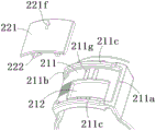
Fig. 5A shows a partially enlarged view of fig. 4 from the top, showing the guide slide groove 211 on the second connector 20 and the catch fuse 220 not yet installed in the guide slide groove 211; fig. 5B shows a partial enlarged view of fig. 4, viewed from the bottom, showing the guide runner 211 on the second connector 20 and the catch fuse 220 not yet installed in the guide runner 211; fig. 6 shows an assembly of the second housing 210 and the catch fuse 220 shown in fig. 5A and 5B.
As shown in fig. 1 to 10, in the illustrated embodiment, a pushing portion 112 is formed on the first housing 110, and the pushing portion 112 is adapted to push the locking fuse 220 from the locking position to a pre-locking position without interference with the elastic locking fuse 111 during the process of inserting the first housing 110 into the second housing 210, so that the plug connector 10 can be inserted smoothly without collision and interference between the elastic locking fuse 111 and the locking fuse 220.
As shown in fig. 3A and fig. 6 to 10, in the illustrated embodiment, a guide slope 112a inclined from the axial direction of the first connector is formed on the pushing portion 112, and the pushing portion 112 contacts and pushes the catch fuse 220 through the guide slope 112a to drive and guide the catch fuse 220 to move from the fuse position to the pre-lock position in the circumferential direction.
As shown in fig. 1 to 10, in the illustrated embodiment, a guide slide groove 211 extending in the circumferential direction is formed on the outer wall of the second housing 210, and the catch fuse 220 is slidably mounted in the guide slide groove 211, and the guide slide groove 211 is used to guide the catch fuse 220 to move between the fuse position and the pre-lock position in the circumferential direction.
As shown in fig. 1 to 10, in the illustrated embodiment, the locking fuse 220 mainly includes a sliding plate 221 and one or more limiting portions 222. The sliding plate 221 is an arc-shaped plate extending in the circumferential direction. The stopper 222 is coupled to the bottom surface of the sliding plate 221. An opening 212 is formed on the second housing 210, and the limiting portion 222 extends into the second housing 210 through the opening 212. In the illustrated embodiment, the opening 212 is located on the bottom wall of the guide chute 211 and is completely blocked by the sliding plate 221.
As shown in fig. 1 to 10, in the illustrated embodiment, the edges of the front and rear sides of the opening 212, which are opposite to each other in the axial direction, are slidably caught in catching grooves between the catching portions 222 and the second housing 210, respectively, to limit the movement of the catch fuse 220 in the radial direction. This allows the locking fuse 220 to move only in the circumferential direction in the guide groove 211.
As shown in fig. 1 to 10, in the illustrated embodiment, the resilient latch 111 mainly includes a resilient cantilever 111a and a latch portion 111 b. The resilient cantilever 111a is connected to the first housing 110 and is adapted to move between a locked position and an unlocked position. The locking portion 111b is formed on the elastic cantilever 111a and is adapted to be locked to the second housing 210. The locking catch 220 includes a tongue-in portion 223 connected to a stopper portion 222, the tongue-in portion 223 being adapted to be inserted into a gap between the resilient cantilever 111a and the outer wall of the first housing 110 to prevent the resilient cantilever 111a from moving to the unlocking position. Thus, the risk of accidental unlocking of the elastic latch 111 due to misoperation of an operator can be avoided.
As shown in fig. 1-10, in the illustrated embodiment, the lead-in ramp 112a of the pusher 112 is adapted to contact and push the tab portion 223 of the latch fuse 220 to move the latch fuse 220 from the fuse position to the prelock position.
As shown in fig. 1 to 10, in the illustrated embodiment, a fixed end of the elastic cantilever 111a is connected with the push part 112 and is fixedly connected to an outer wall of the first housing 110 through the push part 112. However, the present invention is not limited to the illustrated embodiment, and the pushing portion 112 may be separated from the elastic cantilever 111 a.
As shown in fig. 1 to 10, in the illustrated embodiment, the elastic latch 111 further includes a pressing part 111c connected to a free end of the elastic cantilever 111a, the pressing part 111c being exposed to the outside of the second housing 210 when the first housing 110 is inserted into the second housing 210 to allow a human finger to press the pressing part 111 c. Thus, after the latch lock 220 is moved to the pre-lock position, the elastic latch 111 can be unlocked by pressing the pressing portion 111c with a finger.
As shown in fig. 1 to 10, in the illustrated embodiment, two positioning grooves 211g extending in the axial direction are formed in the bottom wall of the guide chute 211, and one positioning rib 221g extending in the axial direction is formed on the inner surface of the slide plate 221. When the locker lock 220 is mounted in the guide slide 211 and moved to the locking position, the positioning rib 221g is positioned in one of the positioning grooves 211 g. When the locker lock 220 is mounted in the guide slide 211 and moved to the pre-lock position, the positioning rib 221g is positioned in the other positioning groove 211 g. The design of the positioning rib 221g and the positioning groove 211g can enhance the operation hand feeling of an operator, and can respectively position the lock catch fuse 220 at a fuse position and a pre-locking position.
As shown in fig. 1 to 10, in the illustrated embodiment, an indication arrow 221f is formed on an outer surface of the sliding plate 221, and a safety position indicator (e.g., a closed lock indicator indicating that the elastic locker 111 is not unlockable) and a pre-lock position indicator (e.g., an open lock indicator indicating that the elastic locker 111 is unlockable) are formed on an outer wall of the second housing 210. When the latch relief 220 is installed in the guide slide 211 and moved to the relief position, the indication arrow 221f points to the relief position indicator. When the latch lock 220 is installed in the guide slide 211 and moved to the pre-lock position, the indication arrow 221f points to the pre-lock position indicator. Therefore, when the indication arrow 221f points to the pre-lock position indicator, the elastic latch 111 can be unlocked by pressing the pressing portion 111c of the elastic latch 111 with a finger.
As shown in fig. 4 to 10, in the illustrated embodiment, the guide chute 211 is surrounded by first and second end walls 211a, 211b that are circumferentially opposite and two side walls 211c that are axially opposite. The catch fuse 220 is adapted to move circumferentially between the first end wall 211a and the second end wall 211b of the guide chute 211.
As shown in fig. 4 to 10, in the illustrated embodiment, the sliding plate 221 includes first and second ends opposite in the circumferential direction and front and rear sides opposite in the axial direction. The first and second ends of the sliding plate 221 correspond to the first and second end walls 211a and 211b of the guide slide groove 211, respectively, and the front and rear sides of the sliding plate 221 correspond to the two side walls 211c of the guide slide groove 211, respectively.
As shown in fig. 4 to 10, in the illustrated embodiment, when the locking fuse 220 is moved to the fuse position along the guide slide groove 211, the end surface of the first end of the sliding plate 221 abuts against the first end wall 211a of the guide slide groove 211, and the top surface of the first end wall 211a of the guide slide groove 211 is higher than the outer surface of the sliding plate 221, so that the end surface of the first end of the sliding plate 221 cannot be touched by human fingers. Thus, the operator cannot push the end surface of the first end of the sliding plate 221 with a finger to reset the locking fuse 220, so that the locking fuse 220 can be prevented from being reset by mistake or accident, and the safety in use is improved.
As shown in fig. 4 to 10, in the illustrated embodiment, the outer surface of the sliding plate 221 is a smooth surface, and in the illustrated embodiment, is a smooth arc surface, so that the friction between the human finger and the outer surface of the sliding plate 221 is not enough to push the catch fuse 220 to move. In this way, the latch guard 220 can be further prevented from being reset erroneously or accidentally, thereby further improving safety in use.
As shown in fig. 4 to 10, in the illustrated embodiment, an insertion groove 221a is formed on an end surface of the first end of the sliding plate 221 or on an inner wall surface of the first end wall 211a of the guide chute 211, and the insertion groove 221a is configured to be inserted by a tool (not shown, for example, a flat-head screwdriver) into which an adult finger cannot be inserted, so that the lock catch 220 can be shifted from the safety position to the pre-lock position by the tool inserted into the insertion groove 221 a. Therefore, in the present invention, to realize the reset operation of the locking device 220 from the safety position to the pre-locking position, a tool must be used, and the user cannot use his finger to realize the reset operation. Therefore, the utility model discloses can effectively avoid hasp insurance 220 to reset by mistake or accident because of operating personnel maloperation, improve the safety in utilization.
As shown in fig. 4 to 10, in the illustrated embodiment, the front and rear side surfaces of the sliding plate 221 respectively abut against the two side walls 211c of the guide chute 211, and the top surfaces of the two side walls 211c of the guide chute 211 are higher than the outer surface of the sliding plate 221, so that the front and rear side surfaces of the sliding plate 221 cannot be touched by a human finger. In this way, the user cannot grasp the front and rear sides of the sliding plate 221 to reset the locking fuse 220, and the locking fuse 220 can be further prevented from being reset by mistake or accident, thereby further improving the safety of use.
As shown in fig. 4 to 10, in the illustrated embodiment, a gap 2110 is formed on the second end wall 211b of the guide chute 211 and/or the top surface of the second end wall 211b of the guide chute 211 is lower than the outer surface of the sliding plate 221 to allow a human finger to touch the end surface of the second end of the sliding plate 221, so that the sliding plate 221 can be pushed by the finger from the pre-lock position to the safety position.
As shown in fig. 4 to 10, in the illustrated embodiment, when the latch lock 220 is moved to the pre-lock position, the second end of the sliding plate 221 abuts against the second end wall 211b of the guide chute 211. In this manner, the latch relief 220 may be defined in a pre-lock position.
It will be appreciated by those skilled in the art that the embodiments described above are exemplary and can be modified by those skilled in the art, and that the structures described in the various embodiments can be freely combined without conflict in structure or principle.
Although the present invention has been described in connection with the accompanying drawings, the embodiments disclosed in the drawings are intended to exemplify preferred embodiments of the present invention, and should not be construed as limiting the present invention.
Although a few embodiments of the present general inventive concept have been shown and described, it would be appreciated by those skilled in the art that changes may be made in these embodiments without departing from the principles and spirit of the general inventive concept, the scope of which is defined in the claims and their equivalents.
It should be noted that the word "comprising" does not exclude other elements or steps, and the words "a" or "an" do not exclude a plurality. Additionally, any element numbers of the claims should not be construed as limiting the scope of the invention.

Claims (14)

1. A connector adapted to mate with a mating connector, the connector comprising:
a housing; and
a locking catch slidably mounted on the housing and movable between a locking position preventing unlocking of the mating connector and a pre-locking position pre-mounting the mating connector on the housing,
a guide chute is formed on an outer wall of the connector, the guide chute being surrounded by first and second end walls spaced from each other in a circumferential direction of the housing and two side walls spaced from each other in an axial direction of the housing;
the lock catch fuse comprises a slide plate slidably mounted in the guide runner, the slide plate including first and second ends spaced apart from each other in the circumferential direction and front and rear sides spaced apart from each other in the axial direction;
when the locking catch is moved along the guide runner into the locking position, the end face of the first end of the slide plate abuts against the first end wall of the guide runner, so that the end face of the first end of the slide plate is not accessible to a human finger.
2. The connector of claim 1, wherein:
the outer surface of the sliding plate is a smooth surface, so that the friction between the fingers of a person and the outer surface of the sliding plate is not enough to push the lock catch to move safely.
3. The connector according to claim 1 or 2, wherein:
a slot is formed on the end face of the first end of the slide plate or on the inner wall face of the first end wall of the guide runner, the slot being configured such that a finger of a person cannot be inserted but a corresponding tool can be inserted, so that the lock catch lock can be moved from the lock position to the pre-lock position by the tool inserted into the slot.
4. The connector of claim 1, wherein:
the side surfaces of the front side and the rear side of the sliding plate are respectively attached to the two side walls of the guide sliding chute, so that the fingers of a person can not contact the side surfaces of the front side and the rear side of the sliding plate.
5. The connector of claim 1, wherein:
a notch is formed in the second end wall of the guide chute and/or the top surface of the second end wall of the guide chute is lower than the outer surface of the slide plate to allow a person's finger to contact the end surface of the second end of the slide plate so that the slide plate can be pushed by the finger from the prelock position to the safety position.
6. The connector of claim 1, wherein:
when the lock catch safety is moved to the pre-lock position, the second end of the slide plate abuts against the second end wall of the guide chute.
7. The connector of claim 1, wherein:
the lock catch fuse also comprises one or more limiting parts which are connected to the sliding plate,
an opening is formed on the shell, the limiting part extends into the shell through the opening,
edges of front and rear sides of the opening, which are opposite in the axial direction, are respectively and slidably clamped in the clamping groove between the limiting part and the shell so as to limit the movement of the lock catch in the radial direction.
8. The connector of claim 7, wherein:
a resilient latch adapted to latch onto the connector is formed on the mating connector,
the latch cutout includes a tongue-in-groove portion connected to the stopper portion, the tongue-in-groove portion being adapted to be inserted into a gap between the resilient latch and the outer wall of the mating connector to prevent the resilient latch from moving to the unlocked position.
9. The connector of claim 1, wherein:
two positioning grooves extending along the axial direction are formed in the bottom wall of the guide sliding chute, and one positioning rib extending along the axial direction is formed on the inner surface of the sliding plate;
when the lock catch is mounted in the guide runner and moved to the catch position, the positioning rib is positioned in a positioning groove;
when the shackle breaker is installed in the guide runner and moved to the prelock position, the positioning rib is positioned in another positioning groove.
10. The connector of claim 1, wherein:
forming an indication arrow on the outer surface of the sliding plate, and forming a safety position mark and a pre-locking position mark on the outer wall of the shell;
when the lock catch safety is installed in the guide chute and moved to the safety position, the indication arrow points to the safety position indicator;
when the shackle breaker is mounted in the guide runner and moved to the pre-lock position, the indicator arrow points to the pre-lock position indicator.
11. The connector of claim 1, further comprising:
and the conductive terminal is arranged in the shell.
12. The connector according to any one of claims 1-2, 4-11, wherein:
the top surface of the first end wall of the guide chute is higher than the outer surface of the slide plate.
13. The connector of claim 12, wherein:
the top surfaces of both side walls of the guide chute are higher than the outer surface of the slide plate.
14. A connector assembly comprising:
a mating connector; and
a connector adapted to mate with the mating connector,
the method is characterized in that:
the connector is according to any one of claims 1-13.
CN202120566205.1U 2021-03-19 2021-03-19 Connector and connector assembly Active CN214625501U (en)

Priority Applications (3)

Application Number Priority Date Filing Date Title
CN202120566205.1U CN214625501U (en) 2021-03-19 2021-03-19 Connector and connector assembly
US17/696,205 US12107366B2 (en) 2021-03-19 2022-03-16 Connector and connector assembly
DE102022106379.8A DE102022106379A1 (en) 2021-03-19 2022-03-18 connector and connector assembly

Applications Claiming Priority (1)

Application Number Priority Date Filing Date Title
CN202120566205.1U CN214625501U (en) 2021-03-19 2021-03-19 Connector and connector assembly

Publications (1)

Publication Number Publication Date
CN214625501U true CN214625501U (en) 2021-11-05

Family

ID=78395692

Family Applications (1)

Application Number Title Priority Date Filing Date
CN202120566205.1U Active CN214625501U (en) 2021-03-19 2021-03-19 Connector and connector assembly

Country Status (3)

Country Link
US (1) US12107366B2 (en)
CN (1) CN214625501U (en)
DE (1) DE102022106379A1 (en)

Families Citing this family (3)

* Cited by examiner, † Cited by third party
Publication number Priority date Publication date Assignee Title
USD1042358S1 (en) * 2021-06-18 2024-09-17 Tyco Electronics (Shanghai) Co., Ltd. Connector housing
CA215847S (en) * 2022-03-25 2024-03-15 Connec Ltd Connector for a power transmission and communications system
CA215848S (en) * 2022-03-25 2024-03-15 Connec Ltd Connector for a power transmission and communications system

Family Cites Families (80)

* Cited by examiner, † Cited by third party
Publication number Priority date Publication date Assignee Title
US4229064A (en) 1978-10-25 1980-10-21 Trw Inc. Polarizing adapter sleeves for electrical connectors
US4542952A (en) 1984-04-27 1985-09-24 Allied Corporation Electrical connector assembly having locking means
US4764129A (en) 1984-09-27 1988-08-16 British Telecommunications Plc Electrical connector assemblies
JPH084705Y2 (en) 1990-11-27 1996-02-07 矢崎総業株式会社 connector
FR2694053B1 (en) 1992-07-24 1994-09-02 Souriau & Cie Bayonet type locking connection assembly.
US5729644A (en) 1996-02-26 1998-03-17 Alcoa Fujikura Limited Receptacle for multi-fiber connector
US5662488A (en) 1996-10-31 1997-09-02 Alden; Peter H. Quick connect coupling system for rapidly joining connectors and/or other elongated bodies
US5984705A (en) 1996-12-02 1999-11-16 Sumitomo Wiring Systems, Ltd. Connector
US5902155A (en) 1997-08-28 1999-05-11 Molex Incorporated Electrical connector assembly
DE19932243A1 (en) 1999-07-06 2001-01-11 Wago Verwaltungs Gmbh Electrical connector
FR2808570B1 (en) 2000-05-04 2002-07-26 Fci France BAYONET TYPE LOCKING CONNECTION ASSEMBLY
JP2002231375A (en) 2001-01-30 2002-08-16 Yazaki Corp Auxiliary module sealing structure
US6852386B2 (en) 2001-03-08 2005-02-08 Norbord Inc. Composite board with OSB faces
US6769813B2 (en) 2001-10-22 2004-08-03 Yu-Feng Cheng Universal optical fiber plug
US6811424B2 (en) * 2003-03-26 2004-11-02 Fci Americas Technology, Inc. Electrical connector having connector position assurance member
US7674046B2 (en) 2003-09-22 2010-03-09 Belden Cdt (Canada) Inc. Fibre optic connector keying system
JP2005267930A (en) 2004-03-17 2005-09-29 Yazaki Corp Rotating mating connector
US7267570B2 (en) * 2005-07-22 2007-09-11 Tyco Electronics Corporation Double beam latch connector
US7347742B2 (en) * 2005-09-02 2008-03-25 Tyco Electronics Corporation Connector assembly including provision for body clip
JP4581947B2 (en) 2005-09-30 2010-11-17 オムロン株式会社 connector
JP4558619B2 (en) 2005-09-30 2010-10-06 矢崎総業株式会社 connector
US7322846B2 (en) 2005-11-04 2008-01-29 Winchester Electronics Corporation Quick connect connector
US7347745B1 (en) * 2007-01-19 2008-03-25 Tyco Electronics Corporation Three position electrical connector assembly
JP4767923B2 (en) 2007-07-27 2011-09-07 タイコエレクトロニクスジャパン合同会社 Electrical connector and connector assembly
DE102007060573B4 (en) 2007-12-15 2010-02-25 Lumberg Connect Gmbh Connector for photovoltaic connection cables
US7645162B2 (en) * 2008-01-24 2010-01-12 Tyco Electronics Corporation Connector assembly having a slider element
JP4820421B2 (en) 2009-01-13 2011-11-24 ホシデン株式会社 connector
US8529288B2 (en) 2010-04-14 2013-09-10 John Mezzalingua Associates, LLC Cover for cable connectors
DE102010021303B4 (en) 2010-04-28 2019-01-17 Amphenol-Tuchel Electronics Gmbh Electrical connector, in particular round connector
US7980894B1 (en) * 2010-08-23 2011-07-19 Tyco Electronics Corporation Coaxial connector with a cable receptor with an outer contact
US8597043B2 (en) * 2011-03-15 2013-12-03 Tyco Electronics Corporation High voltage connector assembly
US9057845B2 (en) 2011-12-31 2015-06-16 Molex Incorporated Multi-ferrule optical fiber cable assembly
DE102012104857B4 (en) 2012-06-05 2016-03-24 Wago Verwaltungsgesellschaft Mbh Electrical plug connection
DE102013018160B3 (en) 2013-12-05 2015-02-12 Wieland Electric Gmbh Electrical plug connection
US8968021B1 (en) * 2013-12-11 2015-03-03 JAE Oregon, Inc. Self-rejecting automotive harness connector
DE202014105733U1 (en) * 2014-11-27 2015-05-28 Erich Jaeger Gmbh & Co. Kg Plug for plugging into a socket
JP6311937B2 (en) 2015-02-12 2018-04-18 株式会社オートネットワーク技術研究所 Connector and shield shell
GB201502871D0 (en) 2015-02-20 2015-04-08 Trolex Ltd Explosion proof connector
DE102015105832B4 (en) 2015-04-16 2017-03-30 Wago Verwaltungsgesellschaft Mbh Electrical connector and method for releasing an electrical connector
US9437961B1 (en) 2015-10-02 2016-09-06 Westinghouse Air Brake Technologies Corporation Two mating electrical power connector assemblies having identical configurations
US9595789B1 (en) * 2016-02-10 2017-03-14 I.D. Systems, Inc. Connector locking mechanism having a sliding connection retention component
EP3420614A4 (en) 2016-02-25 2019-10-16 Molex, LLC Electrical connector
US10153581B2 (en) 2016-03-02 2018-12-11 Vincent Mitchell System and method for connecting to marine shore power
US10038278B2 (en) * 2016-03-17 2018-07-31 Te Connectivity Corporation Electrical connector having a connector position assurance element
US9680256B1 (en) * 2016-03-17 2017-06-13 Te Connectivity Corporation Connector system with connector position assurance
JP6464126B2 (en) 2016-09-15 2019-02-06 矢崎総業株式会社 Packing and shield connector
US9882317B1 (en) * 2016-09-15 2018-01-30 Te Connectivity Corporation Connector system with hybrid electrical connectors
US9929519B1 (en) * 2016-09-22 2018-03-27 Te Connectivity Corporation Electrical cable connector and method of assembling the same
US9837761B1 (en) * 2016-09-22 2017-12-05 Te Connectivity Corporation Electrical cable connector with rotatable housing
JP6819903B2 (en) 2017-01-30 2021-01-27 株式会社オートネットワーク技術研究所 Connector connection structure
CN108511984B (en) * 2017-02-21 2021-07-20 富士康(昆山)电脑接插件有限公司 Electrical connector assembly
DE102017112160A1 (en) 2017-06-01 2018-12-06 R.Stahl Schaltgeräte GmbH Explosion-proof connector
CN207021444U (en) 2017-06-12 2018-02-16 深圳龙友科技股份有限公司 High-tension connector
JP6386138B1 (en) * 2017-07-14 2018-09-05 日本航空電子工業株式会社 connector
JP2019040729A (en) 2017-08-24 2019-03-14 モレックス エルエルシー connector
US10847927B2 (en) 2017-10-05 2020-11-24 Fci Usa Llc Ruggedized connector system
US11383606B2 (en) * 2017-10-10 2022-07-12 Murakami Corporation Port locking actuator device for vehicle inlet
GB2568079A (en) 2017-11-03 2019-05-08 Trolex Ltd Connector coding system
CN109950746B (en) * 2017-12-20 2020-12-22 番禺得意精密电子工业有限公司 Electric connector combination
JP6930467B2 (en) 2018-03-14 2021-09-01 オムロン株式会社 connector
EP3794686B1 (en) 2018-05-16 2023-03-01 Signify Holding B.V. Kit of parts of track and plug
DE102018113365A1 (en) 2018-06-05 2019-12-05 Rosenberger Hochfrequenztechnik Gmbh & Co. Kg Modular connector system
DE102018004589B3 (en) 2018-06-08 2019-10-02 Blv Licht- Und Vakuumtechnik Gmbh Base assembly for receiving a lamp with pinch
JP2020043024A (en) * 2018-09-13 2020-03-19 矢崎総業株式会社 Board connector
JP6981388B2 (en) 2018-10-04 2021-12-15 株式会社オートネットワーク技術研究所 Male connector and connector device
JP6781231B2 (en) 2018-10-24 2020-11-04 矢崎総業株式会社 connector
KR102676844B1 (en) 2018-11-06 2024-06-21 삼성전자주식회사 Adapter and electronic system having the same
DE202018106428U1 (en) * 2018-11-13 2019-05-24 Odu Gmbh & Co. Kg Coupling connector with a slider part
CN111384642A (en) * 2018-12-29 2020-07-07 李尔公司 Electrical connector with connector position assurance member
US10649152B1 (en) * 2019-02-20 2020-05-12 Muh-Chen Yang Connector system
DE102019205050A1 (en) 2019-04-09 2020-10-15 Audi Ag Socket device for safe electrical contact with a corresponding plug device, plug device and battery module for a high-voltage battery
JP6916238B2 (en) 2019-04-15 2021-08-11 矢崎総業株式会社 Rotary connector
JP7159971B2 (en) 2019-05-13 2022-10-25 株式会社オートネットワーク技術研究所 Connector and coupling structure
FR3098031B1 (en) * 2019-06-26 2024-05-31 Radiall Sa Power connection assembly comprising a connection module and electrical cable terminations to be locked/unlocked in the module according to a desired insertion position, Terminal block comprising a plurality of independent connection modules.
CN112217042A (en) 2019-07-12 2021-01-12 康普技术有限责任公司 Bayonet type bundling radio frequency connector assembly
US11070013B2 (en) 2019-09-17 2021-07-20 Te Connectivity Corporation Over-molded coaxial connector assembly
CN110581391A (en) 2019-09-19 2019-12-17 上海航天科工电器研究院有限公司 Quick-locking piston type floating power connector
US11594838B2 (en) 2020-04-28 2023-02-28 Foxconn (Kunshan) Computer Connector Co., Ltd. Connector assembly with connector position assurance
US11381033B2 (en) 2020-08-06 2022-07-05 Onanon, Inc. Self-locking connector
US11715908B2 (en) 2020-12-22 2023-08-01 Zinniatek Limited Electrical connector for a photovoltaic module

Also Published As

Publication number Publication date
US20220302644A1 (en) 2022-09-22
DE102022106379A1 (en) 2022-09-22
US12107366B2 (en) 2024-10-01

Similar Documents

Publication Publication Date Title
CN214625501U (en) Connector and connector assembly
US5984705A (en) Connector
CN102017319B (en) Lever-type connector
US6234826B1 (en) Connector position assurance device
US6261116B1 (en) Connector position assurance element with lock protection feature
CN115548731B (en) Connector device
US6846191B2 (en) Electrical connector assembly
US10910764B2 (en) Coupling connector comprising a slider part
CN115939860B (en) Connector device
KR101797249B1 (en) Connector terminal position assurance device
US7201591B2 (en) Lever-type connector
CN112152018A (en) Connector set with locking device
CN115693224B (en) Socket connectors for connector systems
US3368182A (en) Axially operated coupling device
JP7275275B2 (en) connector
JP2022532689A (en) Female terminal position guarantee (TPA) device for connectors and how to assemble it
CN214589380U (en) Connectors and Connector Components
US12224524B2 (en) Connector assembly with plug, having locking features which are operatively arranged between plug housing and socket housing and are adapted to release portion of insertion path of plug housing and socket housing in rotational position
EP1739795A1 (en) A connector, a connector assembly and assembling method therefor
JP3457172B2 (en) Connector mating structure
EP4092843B1 (en) An anti-electric shock mechanism for a power converter
CN113241557B (en) Unlocking connector and unlocking method thereof
JP2025016992A (en) Lever Type Connector
JP7453087B2 (en) connector
JP5970596B2 (en) Electric connector, electric connector unit, and charger for electric vehicle

Legal Events

Date Code Title Description
GR01 Patent grant
GR01 Patent grant