SUMMERY OF THE UTILITY MODEL
To the above situation, for overcoming prior art's defect, the utility model provides a gastrointestinal fluid pressure relief device for gastrointestinal surgery, the utility model discloses novel structure, think about ingeniously, easy operation is convenient, the effectual problem that negative pressure size can not be regulated and control of having solved has reached the purpose of being convenient for dredge the stomach tube, the defect of unable used repeatedly has been avoided, the function of patient's drainage thing observation of being convenient for has been optimized, the purpose that can calculate the drainage volume has been reached, the problem of inside unable cleaning and disinfection has been solved, the defect of the unable observation of pressure size has been avoided, patient's uncomfortable sense has been alleviateed, the purpose of being convenient for to remove has been reached, medical personnel's nurse pressure has been reduced.
In order to achieve the above object, the utility model provides a following technical scheme: the utility model discloses a box, the front end of box is equipped with a crank, and the crank internal rotation is connected with a screw rod, and the outside screw-thread fit of screw rod has a slider, and the slider is arranged in the crank and can slide around the crank, the crank internal rotation is connected with a drive bevel gear, and drive bevel gear's front end is equipped with an adjusting disk, and drive bevel gear meshing has a driven bevel gear, and driven bevel gear and screw rod fixed connection, the front end of box rotates and is connected with a rocker, and the middle part of rocker has seted up the sliding tray, and the slider is arranged in the sliding tray and can slide around the sliding tray, the lower extreme of rocker rotates and is connected with a connecting rod, the front end of box is equipped with an air pump mechanism, is equipped with a stay cord between air pump mechanism and the connecting rod;
be equipped with a catch basin in the box, be equipped with one in the catch basin and follow the gliding piston plate from top to bottom of catch basin, the upper end left side of catch basin is equipped with an intake pipe, an outlet duct and a decompression shell, is equipped with one in the decompression shell and can follows the rubber buffer of decompression shell horizontal slip, and the left end of rubber buffer is equipped with a supporting spring, it has a plurality of pressure release grooves to open in the decompression shell, the lower extreme intercommunication of decompression shell has an blast pipe, and the other end of blast pipe runs through the left side of box.
Preferably, the upper end is equipped with the collecting tank in the box, and the front end of collecting tank is equipped with the glass board, and the position that the box corresponds the glass board is equipped with the scale, and the left side of glass board is equipped with a manometer, the top of collecting tank is equipped with the scavenge pipe, and the collecting tank is run through to one side of scavenge pipe, the scavenge pipe tip is equipped with a toper stopper, the left end screw-thread fit of collecting tank has a tube cap, and the below of collecting tank is equipped with an air cleaner, air cleaner and intake pipe intercommunication.
Preferably, the air pump mechanism is including an air pump shell, is equipped with a backup pad that can follow air pump shell gliding from top to bottom in the air pump shell, and a plurality of gas pockets have been seted up to the upper end of backup pad, and the lower extreme of backup pad is equipped with a rubber membrane, backup pad and stay cord fixed connection, be equipped with an air pump extension spring between the upper end of air pump shell and the backup pad, the upper end and the collecting tank intercommunication of support shell, the lower extreme and the air cleaner intercommunication of support shell.
Preferably, the right side of box rotates and is connected with a V-arrangement frame, and the front end of V-arrangement frame is equipped with the back flow, and the other end of back flow and the lower extreme intercommunication of catch basin, the rear end of V-arrangement frame is equipped with the collector tube, the other end and the collector basin UNICOM of collector tube, be equipped with one between the lower extreme of V-arrangement frame and the box and tighten up the extension spring, the top of box is equipped with a drainage tube, and collector tube and back flow all communicate with the one end of drainage tube.
Preferably, the left side intercommunication of catch basin has a moisturizing pipe, and the other end of moisturizing pipe runs through the upper end of box, the tip screw-thread fit of moisturizing pipe has a closing cap, and the lower extreme of closing cap is equipped with a rubber gasket, the upper end of moisturizing pipe is equipped with a groove of giving vent to anger, goes out the groove and communicates with the outlet duct.
Preferably, be equipped with a motor in the box, the tip and the crank of motor are connected, the front end of box rotates and is connected with a band pulley, and the outside of band pulley is arranged in to the stay cord, and the upper end of box is equipped with a plurality of thing grooves of putting, and the lower extreme of box is equipped with a plurality of universal wheels that can lock.
The utility model discloses novel structure, think about ingeniously, easy operation is convenient, through the effectual problem of negative pressure size uncontrollable of having solved of this design, the purpose of being convenient for dredge the stomach tube has been reached, the defect of unable used repeatedly has been avoided, the function of being convenient for observe of patient's drainage thing has been optimized, the purpose that can calculate the drainage volume has been reached, the problem of inside unable cleaning and disinfecting has been solved, the defect of the unable observation of pressure size has been avoided, the uncomfortable sense of patient has been alleviateed, the purpose of being convenient for remove has been reached, medical personnel's nurse pressure has been reduced.
Drawings
The accompanying drawings are included to provide a further understanding of the invention, and are incorporated in and constitute a part of this specification, illustrate embodiments of the invention, and together with the description serve to explain the invention and not to limit the invention. In the drawings:
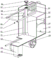
fig. 1 is a schematic view of the overall structure of the present invention.
Fig. 2 is a schematic structural view of the middle crank of the present invention.
Fig. 3 is a schematic structural diagram of the interior of the middle box body of the present invention.
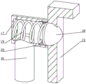
Fig. 4 is an internal schematic view of the middle pressure reducing housing of the present invention.
Fig. 5 is a schematic structural diagram of the gas pump mechanism of the present invention.
Fig. 6 is a partially enlarged schematic view of the area a in fig. 5 according to the present invention.
Fig. 7 is a schematic structural view of the V-shaped frame of the present invention.
In the figure: 1-box body, 2-crank, 3-screw rod, 4-slide block, 5-driving bevel gear, 6-adjusting disc, 7-driven bevel gear, 8-rocker, 9-sliding groove, 10-connecting rod, 11-air pump mechanism, 12-pull rope, 13-water storage tank, 14-piston plate, 15-air inlet pipe, 16-air outlet pipe, 17-decompression shell, 18-rubber plug, 19-supporting spring, 20-pressure release groove, 21-air outlet pipe, 22-liquid collection groove, 23-glass plate, 24-scale, 25-pressure gauge, 26-cleaning pipe, 27-conical plug, 28-pipe cover, 29-air filter, 30-V-shaped frame, 31-return pipe, 32-liquid collection pipe, 33-tension spring, 34-drainage tube, 35-liquid supplement tube, 36-sealing cover, 37-rubber gasket, 38-air outlet groove, 39-motor, 40-belt wheel, 41-storage groove, 42-universal wheel, 43-air pump shell, 44-support plate, 45-air hole, 46-rubber membrane and 47-air pump tension spring.
Detailed Description
The following describes the present invention in further detail with reference to fig. 1-7.
Embodiment one, from fig. 1-4, the utility model comprises a box body 1, in order to achieve the purpose of negative pressure regulation, the front end of the box body 1 is provided with a crank 2, a screw rod 3 is connected in the crank 2 in a rotating way, the outer side of the screw rod 3 is provided with a slide block 4 in a screw-thread fit way, the slide block 4 is arranged in the crank 2 and can slide back and forth along the crank 2, the left and right sides of the slide block 4 are provided with trapezoidal protrusions which can prevent the slide block 4 from sliding out of the crank 2 when sliding back and forth, a driving bevel gear 5 is connected in the crank 2 in a rotating way, the front end of the driving bevel gear 5 is provided with an adjusting disc 6, in order to facilitate the adjustment, the front side of the adjusting disc 6 is frosted, the driving bevel gear 5 is engaged with a driven bevel gear 7, the driven bevel gear 7 is fixedly connected with the screw rod 3, the adjusting disc 6 can be pressed by fingers when adjusting, the driving bevel gear 5 drives the driven bevel gear 7 to rotate, the screw rod 3 is rotated by the driven bevel gear 7 to achieve the purpose of adjusting the position of the sliding block 4, when the driving bevel gear 5 is not rotated, the screw rod 3 and the sliding block 4 complete self-locking through threads, the front end of the box body 1 is rotatably connected with a rocker 8, the middle part of the rocker 8 is provided with a sliding groove 9, the sliding block 4 is arranged in the sliding groove 9 and can slide back and forth along the sliding groove 9, the lower end of the rocker 8 is rotatably connected with a connecting rod 10, the crank 2, the sliding block 4 and the rocker 8 are mutually matched to form a limiting structure of the connecting rod 10, the sliding block 4 and the screw rod 3 are mutually matched to form a limiting structure of the rocker 8, the connecting rod 10 has different time for moving left and right due to the quick return characteristic when the rocker 8 and the crank 2 are mutually matched, the front end of the box body 1 is provided with an air pump mechanism 11, a pull rope 12 is arranged between the air pump mechanism 11 and the connecting rod 10, and the pull rope 12 is made of flexible steel wire rope, when the device is used, the crank 2 rotates to drive the sliding block 4 to synchronously rotate, the sliding block 4 slides along the sliding groove 9 to enable the rocker 8 to swing, the rocker 8 swings to drive the connecting rod 10 and the pull rope 12 to move, and the swinging range of the rocker 8 is controlled by adjusting the position of the sliding block 4, so that the purpose of controlling the traveling distance of the pull rope 12 is achieved;
in order to achieve the purpose of avoiding blockage, a water storage tank 13 is arranged in the box body 1, a piston plate 14 capable of sliding up and down along the water storage tank 13 is arranged in the water storage tank 13, the upper end of the piston plate 14 is a cavity, the lower end of the piston plate 14 is normal saline, waterproof rubber is used on the surface of the piston plate 14, a plastic plate is used inside the piston plate, elongated protruding rod-shaped structures are arranged at each edge angle of the piston plate 14, the piston plate 14 is prevented from overturning when sliding in the water storage tank 13, an air inlet pipe 15 is arranged on the left side of the upper end of the water storage tank 13, an air outlet pipe 16 and a pressure reducing shell 17 are arranged, the pressure reducing shell 17 is fixedly connected with the water storage tank 13, a rubber plug 18 capable of sliding left and right along the pressure reducing shell 17 is arranged in the pressure reducing shell 17, the rubber plug 18 penetrates through one side of the water storage tank 13, the right end of the rubber plug 18 is conical, and the problem that the rubber plug 18 cannot normally reset is effectively avoided, rubber buffer 18's left end is equipped with a supporting spring 19, it has a plurality of pressure release grooves 20 to open in the decompression shell 17, the lower extreme intercommunication of decompression shell 17 has an exhaust pipe 21, the other end of exhaust pipe 21 runs through the left side of box 1, the air enters into catch basin 13 through intake pipe 15 during the use, make the air form the atmospheric pressure district in the upper end of piston plate 14, after atmospheric pressure reaches the certain degree, air promotion rubber buffer 18 removes left, the air gets into the rear end of rubber buffer 18 through pressure release groove 20 this moment, discharge in the exhaust pipe 21 afterwards, supporting spring 19 resets rubber buffer 18 after piston plate 14 upper end atmospheric pressure reduces.
In the second embodiment, on the basis of the first embodiment, as shown in fig. 3 and 5, in order to observe the body fluid discharge amount of the patient, a liquid collecting tank 22 is disposed at the upper end in the box body 1, a glass plate 23 is disposed at the front end of the liquid collecting tank 22, a scale 24 is disposed at the position of the box body 1 corresponding to the glass plate 23, in order to observe the pressure condition in the liquid collecting tank 22 and facilitate adjustment at any time, a pressure gauge 25 is disposed at the left side of the glass plate 23, in order to achieve the purpose of cleaning and disinfecting the inside, a cleaning pipe 26 is disposed above the liquid collecting tank 22, a plurality of water spraying holes are disposed on the cleaning pipe 26 to make the inside cleaning more comprehensive and reduce the cleaning dead angle, one side of the cleaning pipe 26 penetrates through the liquid collecting tank 22, a tapered plug 27 is disposed at the end of the cleaning pipe 26, the tapered plug 27 is made of rubber material, the diameter of the left end of the tapered plug 27 is increased, so as to prevent the tapered plug 27 from being sucked into the cleaning pipe 26 by negative pressure, in order to facilitate the operation, the left end of toper stopper 27 is equipped with the pull ring, the left end screw-thread fit of collecting tank 22 has a tube cap 28, for avoiding the weeping, the right-hand member of tube cap 28 is equipped with waterproof gasket, the below of collecting tank 22 is equipped with an air cleaner 29, air cleaner 29 is prior art, do not do too much description here, air cleaner 29 and intake pipe 15 intercommunication, when disinfecting to inside washing, pull down tube cap 28 earlier, make the interior liquid discharge of collecting tank 22, extract toper stopper 27 afterwards, insert the water pipe on scavenge pipe 26, use rivers to wash inside, can add the antiseptic solution in abluent rivers and disinfect inside.
In the third embodiment, based on the second embodiment, as shown in fig. 3, 5 and 6, in order to achieve the purpose of generating negative pressure in the liquid collecting tank 22, the air pump mechanism 11 includes an air pump housing 43, the air pump housing 43 is fixedly connected with the tank body 1, a supporting plate 44 capable of sliding up and down along the air pump housing 43 is disposed in the air pump housing 43, a plurality of air holes 45 are disposed at the upper end of the supporting plate 44, a rubber membrane 46 is disposed at the lower end of the supporting plate 44, the rubber membrane 46 has certain flexibility, the supporting plate 44 is fixedly connected with the pull rope 12, an air pump tension spring 47 is disposed between the upper end of the air pump housing 43 and the supporting plate 44, the upper end of the supporting housing is communicated with the liquid collecting tank 22, the lower end of the supporting housing is communicated with the air filter 29, when in use, the supporting plate 44 is pulled by the air pump spring 47 to move upward, and the air flows downward from above the supporting plate 44, the air pushes up the rubber membrane 46 by a gap through the air hole 45, then the air flows to the lower part of the support plate 44 from the gap, then the support plate 44 is pulled to move downwards through the pull rope 12, the air hole 45 is sealed by the rubber membrane 46, the air cannot flow to the upper part of the support plate 44, the air can be discharged into the air filter 29 only from the lower end of the air pump shell 43, the purpose of controlling the formation of the support plate 44 is achieved by adjusting the travel distance of the pull rope 12, the negative pressure in the liquid collecting tank 22 is smaller when the stroke of the support plate 44 is shorter, and the negative pressure in the liquid collecting tank 22 is larger when the stroke of the support plate 44 is longer.
In the fourth embodiment, on the basis of the first embodiment, as shown in fig. 7, in order to prevent the liquid in the water storage tank 13 from entering the liquid collection tank 22, a V-shaped frame 30 is rotatably connected to the right side of the box body 1, a return pipe 31 is arranged at the front end of the V-shaped frame 30, the portion of the return pipe 31 corresponding to the V-shaped frame 30 is made of soft rubber, the other end of the return pipe 31 is communicated with the lower end of the water storage tank 13, a liquid collection pipe 32 is arranged at the rear end of the V-shaped frame 30, the other end of the liquid collection pipe 32 is communicated with the liquid collection tank 22, in order to observe the color condition of the patient drainage, the liquid collection pipe 32 is made of transparent silica gel, in order to prevent the V-shaped frame 30 from shifting when not affected by external force, a tension spring 33 is arranged between the lower end of the V-shaped frame 30 and the box body 1, in order to facilitate operation, a handle is arranged at the right end of the V-shaped frame 30, a drainage pipe 34 is arranged above the box body 1, the liquid collecting pipe 32 and the return pipe 31 are both communicated with one end of the drainage pipe 34, the drainage pipe 34 is made of silica gel, the drainage pipe 34 can be trimmed and replaced, when the device is used, one end of the drainage pipe 34 is inserted into the stomach of a patient to reduce the pressure of the stomach and intestine of the patient, when the drainage pipe 34 needs to be dredged, the handle of the V-shaped frame 30 is pressed to enable the return pipe 31 to be communicated with the drainage pipe 34, the piston plate 14 in the water storage tank 13 moves downwards under the pressure of air pressure, liquid at the lower end of the piston plate 14 is extruded out, the liquid enters the stomach of the patient through the return pipe 31 and the drainage pipe 34, when the handle of the V-shaped frame 30 is loosened, the tension spring 33 is tightened to pull the V-shaped frame 30 back, the liquid collecting pipe 32 is communicated with the drainage pipe 34, and the return pipe 31 is extruded and sealed by the V-shaped frame 30.
Fifth embodiment, on the basis of the fourth embodiment, as shown in fig. 3, in order to achieve the purpose of replenishing liquid in the cistern 13, the left side of the cistern 13 is communicated with a liquid replenishing pipe 35, the other end of the liquid replenishing pipe 35 penetrates through the upper end of the tank body 1, the end of the liquid replenishing pipe 35 is in threaded fit with a sealing cover 36, in order to ensure the sealing property, the lower end of the sealing cover 36 is provided with a rubber gasket 37, in order to avoid that the piston plate 14 cannot rise normally under the air pressure during liquid replenishing so that liquid cannot smoothly enter the cistern 13, the upper end of the liquid replenishing pipe 35 is provided with an air outlet groove 38, the air outlet groove 38 is communicated with the air outlet pipe 16, and the rubber gasket 37 is slightly larger than the air outlet groove 38, so that air is prevented from flowing out when the cistern is closed.
Sixth embodiment, on the basis of the second embodiment, as shown in fig. 1, 2 and 5, in order to achieve a better purpose, a motor 39 is disposed in the box body 1, an end portion of the motor 39 is connected with the crank 2, a pulley 40 is rotatably connected to a front end of the box body 1, the pull rope 12 is disposed outside the pulley 40, in order to achieve a purpose of placing medical tools during use, a plurality of storage slots 41 are disposed at an upper end of the box body 1, in order to achieve a purpose of facilitating movement, a plurality of lockable universal wheels 42 are disposed at a lower end of the box body 1, and the universal wheels 42 are prior art and will not be described herein.
When the utility model is used, firstly, the length of the drainage tube 34 at the proper position is measured, then the drainage tube 34 is trimmed, lubricating oil is smeared at the front end of the drainage tube 34, the drainage tube 34 is slowly inserted into the stomach of a patient from the nasal cavity of the patient, then the adjusting disc 6 is pressed by fingers to rotate the adjusting slider 4 to the proper position, then the motor 39 is started, the crank 2 rotates to drive the slider 4 to synchronously rotate, the slider 4 slides along the sliding groove 9 to enable the rocker 8 to swing, the rocker 8 swings to drive the connecting rod 10 and the pull rope 12 to move, when the rocker swings leftwards, the pull rope 12 moves leftwards, the air pump tension spring 47 pulls the supporting plate 44 to move upwards, the air flows downwards from the upper part of the supporting plate 44, the air pushes up the rubber membrane 46 to form a gap through the air hole 45, then the air flows from the gap to the lower part of the supporting plate 44, when the rocker swings rightwards, the pull rope 12 pulls the supporting plate 44 to move downwards, the rubber membrane 46 seals the air hole 45, air can not flow to the upper part of the supporting plate 44, so that the air can only be discharged into the air filter 29 from the lower end of the air pump shell 43, the pressure gauge 25 is observed, the motor 39 is closed when the pressure needs to be adjusted, then the air in the air filter 29 enters the upper end of the piston plate 14 in the water storage tank 13 through the air inlet pipe 15 at the position of the adjusting slide block 4, the air forms an air pressure area at the upper end of the piston plate 14, when the air pressure reaches a certain degree, the air pushes the rubber plug 18 to move leftwards, at the same time, the air enters the rear end of the rubber plug 18 through the pressure release tank 20 and then is discharged from the air outlet pipe 21, when the air pressure at the upper end of the piston plate 14 is reduced, the supporting spring 19 resets the rubber plug 18, when the drainage pipe 34 needs to be dredged, the handle of the V-shaped frame 30 is pressed to enable the return pipe 31 to be communicated with the drainage pipe 34, the piston plate 14 in the water storage tank 13 moves downwards under the air pressure, so as to extrude the liquid at the lower end of the piston plate 14, liquid enters the stomach of a patient through the return pipe 31 and the drainage pipe 34 to achieve the purpose of dredging the drainage pipe 34, then the handle of the V-shaped frame 30 is loosened, the tension spring 33 is tightened to pull the V-shaped frame 30 back, the liquid collecting pipe 32 is communicated with the drainage pipe 34, the return pipe 31 is squeezed and sealed by the V-shaped frame 30, after the patient receives reduced pressure, the device is moved to a proper position, then the pipe cover 28 is detached, liquid in the liquid collecting tank 22 is discharged, then the conical plug 27 is pulled out, the water pipe is connected to the cleaning pipe 26, the interior is cleaned through water flow, disinfectant can be added into the cleaned water flow to disinfect the interior, and the device is convenient to use next time.
The utility model discloses novel structure, think about ingeniously, easy operation is convenient, through the effectual problem of negative pressure size uncontrollable of having solved of this design, the purpose of being convenient for dredge the stomach tube has been reached, the defect of unable used repeatedly has been avoided, the function of being convenient for observe of patient's drainage thing has been optimized, the purpose that can calculate the drainage volume has been reached, the problem of inside unable cleaning and disinfecting has been solved, the defect of the unable observation of pressure size has been avoided, the uncomfortable sense of patient has been alleviateed, the purpose of being convenient for remove has been reached, medical personnel's nurse pressure has been reduced.
Finally, it should be noted that: although the present invention has been described in detail with reference to the foregoing embodiments, it will be apparent to those skilled in the art that modifications may be made to the embodiments described in the foregoing embodiments, or equivalents may be substituted for elements thereof. Any modification, equivalent replacement, or improvement made within the spirit and principle of the present invention should be included in the protection scope of the present invention.