Box transformer substation folding door convenient to operate
Technical Field
The utility model belongs to the technical field of the case becomes the frame, concretely relates to case becomes folding door convenient to operation.
Background
A box-type substation, also called a pre-installed substation or a pre-installed substation, is factory prefabricated indoor and outdoor compact distribution equipment which is composed of high-voltage switch equipment, a distribution transformer and a low-voltage distribution device which are arranged into a whole according to a certain wiring scheme. The box becomes the frame and is the cabinet style, and box becomes the cabinet door and has various styles such as push-and-pull door, vertical hinged door, folding door, is convenient for overhaul internal fault.
The cabinet door that current case becomes adopts the folding door, has a plurality of door plants of folding door to rotate to connect, and when opening a door plant, the effort that other door plant received is big inadequately, leads to the opening that the folding door is smooth and easy inadequately, and the operation is convenient inadequately, nimble problem, we provide the case that is convenient for operate for this reason and become the folding door.
SUMMERY OF THE UTILITY MODEL
An object of the utility model is to provide a case becomes folding door convenient to operation to the case that proposes in solving above-mentioned background art becomes the cabinet door and adopts the folding door, has a plurality of door plants of folding door to rotate to connect, and when opening a door plant, the effort that other door plant received is big inadequately, leads to the not smooth and easy opening of folding door inadequately, and the operation is convenient, nimble problem inadequately.
In order to achieve the above object, the utility model provides a following technical scheme: the utility model provides a case becomes folding door convenient to operation, includes door frame, folding door plant is including rotating door plant, well door plant, limit door plant, be equipped with the holding rod on the well door plant intermediate position, be equipped with the slide bar that runs through on the holding rod, the outside of slide bar is equipped with spring, swivel becket, the slide bar is close to the intermediate position and is equipped with the gag lever post, the tip of slide bar is equipped with the dead lever, be equipped with the connecting rod on the swivel becket, the tip of connecting rod is equipped with spacing ball, spacing hole has been seted up on the surface of holding rod, be equipped with the connecting plate on the rotating door plant, be equipped with the location hemisphere on the connecting plate.
Preferably, the holding rod comprises a connecting portion and a holding portion, the connecting portion is arc-shaped and is located on the middle door plate, the holding portion is in an inclined state, and an anti-slip pad made of plastic and provided with inclined grains is arranged on the outer side of the holding portion.
Preferably, the holding rod is provided with a sliding groove, the bottom end of the sliding rod is of a T-shaped structure, a ring plate is sleeved on the outer side of the sliding rod, the bottom end of the spring is connected with the sliding rod, the top end of the spring is connected with the ring plate, and the sliding rod is connected with the holding rod in a sliding mode.
Preferably, the end part of the limiting rod connected with the sliding rod is arc-shaped, and the end part of the limiting rod far away from the sliding rod is matched with the limiting hole.
Preferably, the connecting plate includes vertical board, hang plate, and the vertical board of connecting plate closes the connection on rotating the door plant through the screw soon, the location hemisphere is connected with the hang plate, the ball groove has been seted up on the location hemisphere, spacing ball and ball groove cooperation.
Preferably, the rotating ring is sleeved outside the arc-shaped end of the holding rod, the connecting rod is arc-shaped, and a moving groove for the connecting rod to slide is formed in the positioning hemisphere.
Preferably, be equipped with the fixed block on the door plant in the folding door plant, be equipped with the slide between the fixed block, the slide is connected with fixed block sliding block, the slide avris is equipped with the handle, rotate the door plant and pass through hinge connection with well door plant, well door plant and limit door plant, the slide is located hinge side position.
Compared with the prior art, the beneficial effects of the utility model are that:
1. through holding rod, connecting plate, location hemisphere, connecting rod, the spacing ball that sets up, hold the handle on the folding door plant on the one hand and hold the holding rod on the other hand, open the board of limit and slide toward the position that rotates the door plant, the holding rod receives the effort and outwards opens and rotate the door plant and outwards open along with well door plant, the operation of being convenient for easily opens folding door plant.
2. Through the slide that sets up, the slide covers the connection hinge on the folding door plant, avoids accumulating dust impurity on the hinge and reduces hinge sensitivity of rotation.
Drawings
Fig. 1 is a schematic structural view of the present invention;
FIG. 2 is a schematic top view of the grip of the present invention;
FIG. 3 is a schematic top view of the connection plate of the present invention;
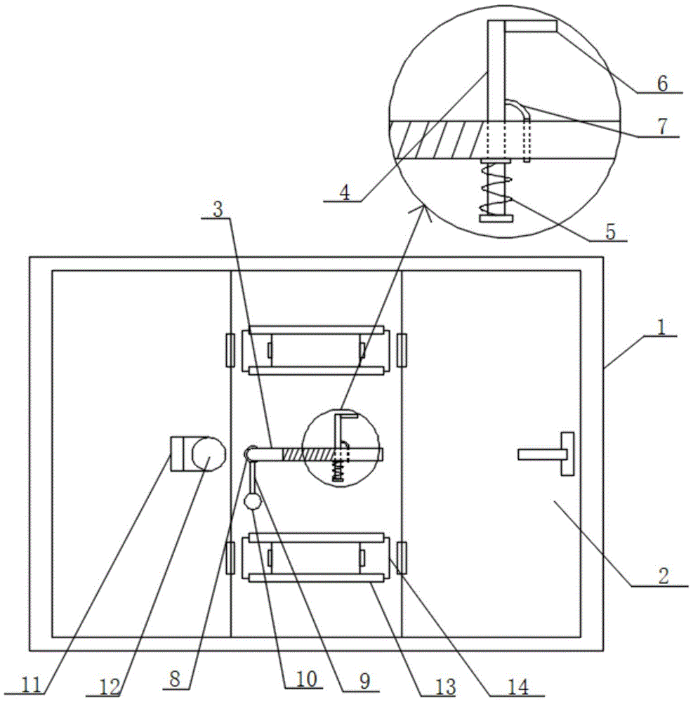
in the figure: 1. a door frame; 2. folding the door panel; 3. a holding rod; 4. a slide bar; 5. a spring; 6. fixing the rod; 7. a limiting rod; 8. a rotating ring; 9. a connecting rod; 10. a limiting ball; 11. a connecting plate; 12. positioning a hemisphere; 13. a fixed block; 14. a slide plate; 15. and a limiting hole.
Detailed Description
The technical solutions in the embodiments of the present invention will be described clearly and completely with reference to the accompanying drawings in the embodiments of the present invention, and it is obvious that the described embodiments are only some embodiments of the present invention, not all embodiments. Based on the embodiments in the present invention, all other embodiments obtained by a person skilled in the art without creative work belong to the protection scope of the present invention.
Examples
Referring to fig. 1 to 3, the present invention provides a technical solution: a box transformer substation folding door convenient to operate comprises a door frame 1 and a folding door plate 2, wherein the folding door plate 2 comprises a rotating door plate, a middle door plate and a side door plate, a holding rod 3 is arranged at the middle position of the middle door plate, a through sliding rod 4 is arranged on the holding rod 3, a spring 5 and a rotating ring 8 are arranged on the outer side of the sliding rod 4, a limiting rod 7 is arranged at the position, close to the middle position, of the sliding rod 4, a fixing rod 6 is arranged at the end part of the sliding rod 4, a connecting rod 9 is arranged on the rotating ring 8, a limiting ball 10 is arranged at the end part of the connecting rod 9, a limiting hole 15 is formed in the surface of the holding rod 3, a connecting plate 11 is arranged on the rotating door plate 11, a positioning hemisphere 12 is arranged on the connecting plate 11, a handle on the upper door plate of the folding door plate 2 is held by one hand, the holding rod 3 is held by the other hand, the side door plate is opened and slides towards the position of the rotating door plate, the holding rod 3 is opened outwards under the action force, the connecting plate 9 drives the connecting plate 11 and the positioning hemisphere 12, the rotating door plate is opened outwards along with the middle door plate, so that the operation is convenient, and the folding door plate 2 is easy to open.
In this embodiment, the holding rod 3 includes connecting portion, the portion of gripping, and connecting portion are arc and connecting portion are located well door plant, and the portion of gripping is in the tilt state, and the portion of gripping outside is equipped with the slipmat of taking the plastics manufacture of oblique line, is convenient for hold the holding rod 3.
In this embodiment, the handle 3 is provided with a sliding groove, the bottom end of the sliding rod 4 is of a T-shaped structure, the outer side of the sliding rod 4 is sleeved with a ring plate, the bottom end of the spring 5 is connected with the sliding rod 4, the top end of the spring is connected with the ring plate, the sliding rod 4 is connected with the handle 3 in a sliding manner, the end part of the limiting rod 7 connected with the sliding rod 4 is in an arc shape, the end part of the limiting rod 7 far away from the sliding rod 4 is matched with the limiting hole 15, the position of the sliding rod 4 can be conveniently adjusted, the limiting rod 7 penetrates through the limiting hole 15, and the sliding rod 4 is limited and fixed.
In this embodiment, connecting plate 11 includes vertical board, the hang plate, 11 vertical boards of connecting plate close the connection on rotating the door plant through the screw soon, location hemisphere 12 is connected with the hang plate, the ball groove has been seted up on the location hemisphere 12, spacing ball 10 and ball groove cooperation, 8 covers of swivel becket are established in the 3 arc ends outsides of holding rod, connecting rod 9 is the arc shape, set up on the location hemisphere 12 and supply the gliding shifting chute of connecting rod 9, on spacing ball 10 embedding location hemisphere 12, when folding door plant 2 is opened outward, hold holding rod 3 and be used in on well door plant, make well door plant move outward, rotating the door plant and receiving the effort and move outward, and the operation of being convenient for, easily open folding door plant 2.
In this embodiment, be equipped with fixed block 13 on the door plant in folding door plant 2, be equipped with slide 14 between the fixed block 13, slide 14 is connected with 13 sliding block of fixed block, and 14 avris of slide are equipped with the handle, rotate door plant and well door plant, well door plant and limit door plant and pass through hinge connection, and slide 14 is located hinge lateral position, and slide 14 slides, and slide 14 covers the connection hinge, avoids accumulating dust impurity on the hinge and reduces hinge sensitivity of rotation.
The utility model discloses a theory of operation and use flow:
when a folding door is installed on a box transformer substation, a door frame 1 is connected in a screwed manner through screws, when a folding door panel 2 is opened, a sliding rod 4 is pinched and moves upwards, a spring 5 is in a contraction state, the sliding rod 4 is moved to a proper position, the sliding rod 4 is loosened, the spring 5 extends from the contraction state, a limiting rod 7 penetrates through a holding rod 3, the sliding rod 4 is limited and fixed, a connecting rod 9 is rotated, a limiting ball 10 is placed on a positioning hemisphere 12, a handle on the upper door panel of the folding door panel 2 is held by one hand, the holding rod 3 is held by the other hand, the side door panel is opened and slides towards the position of the rotating door panel, the holding rod 3 is opened outwards under acting force, the connecting rod 9 drives a connecting plate 11 and the positioning hemisphere 12, the rotating door panel is opened outwards along with a middle door panel, the operation is convenient, and the folding door panel 2 is easy to open;
the rotating door plate is connected with the middle door plate and the side door plate through hinges, the sliding plate 14 is located at the side position of the hinge, the sliding plate 14 slides, the sliding plate 14 covers the connecting hinge on the folding door plate 2, and dust and impurities are prevented from accumulating on the hinge to reduce the rotating sensitivity of the hinge.
Although embodiments of the present invention have been shown and described, it will be appreciated by those skilled in the art that changes, modifications, substitutions and alterations can be made in these embodiments without departing from the principles and spirit of the invention, the scope of which is defined in the appended claims and their equivalents.