CN212282439U - An all-glass atomizer - Google Patents
An all-glass atomizer Download PDFInfo
- Publication number
- CN212282439U CN212282439U CN202020730938.XU CN202020730938U CN212282439U CN 212282439 U CN212282439 U CN 212282439U CN 202020730938 U CN202020730938 U CN 202020730938U CN 212282439 U CN212282439 U CN 212282439U
- Authority
- CN
- China
- Prior art keywords
- base
- oil
- glass
- pressing piece
- suction nozzle
- Prior art date
- Legal status (The legal status is an assumption and is not a legal conclusion. Google has not performed a legal analysis and makes no representation as to the accuracy of the status listed.)
- Withdrawn - After Issue
Links
Images




Classifications
-
- A—HUMAN NECESSITIES
- A24—TOBACCO; CIGARS; CIGARETTES; SIMULATED SMOKING DEVICES; SMOKERS' REQUISITES
- A24F—SMOKERS' REQUISITES; MATCH BOXES; SIMULATED SMOKING DEVICES
- A24F40/00—Electrically operated smoking devices; Component parts thereof; Manufacture thereof; Maintenance or testing thereof; Charging means specially adapted therefor
- A24F40/10—Devices using liquid inhalable precursors
-
- A—HUMAN NECESSITIES
- A24—TOBACCO; CIGARS; CIGARETTES; SIMULATED SMOKING DEVICES; SMOKERS' REQUISITES
- A24F—SMOKERS' REQUISITES; MATCH BOXES; SIMULATED SMOKING DEVICES
- A24F40/00—Electrically operated smoking devices; Component parts thereof; Manufacture thereof; Maintenance or testing thereof; Charging means specially adapted therefor
- A24F40/40—Constructional details, e.g. connection of cartridges and battery parts
- A24F40/42—Cartridges or containers for inhalable precursors
-
- A—HUMAN NECESSITIES
- A24—TOBACCO; CIGARS; CIGARETTES; SIMULATED SMOKING DEVICES; SMOKERS' REQUISITES
- A24F—SMOKERS' REQUISITES; MATCH BOXES; SIMULATED SMOKING DEVICES
- A24F40/00—Electrically operated smoking devices; Component parts thereof; Manufacture thereof; Maintenance or testing thereof; Charging means specially adapted therefor
- A24F40/40—Constructional details, e.g. connection of cartridges and battery parts
- A24F40/44—Wicks
-
- A—HUMAN NECESSITIES
- A24—TOBACCO; CIGARS; CIGARETTES; SIMULATED SMOKING DEVICES; SMOKERS' REQUISITES
- A24F—SMOKERS' REQUISITES; MATCH BOXES; SIMULATED SMOKING DEVICES
- A24F40/00—Electrically operated smoking devices; Component parts thereof; Manufacture thereof; Maintenance or testing thereof; Charging means specially adapted therefor
- A24F40/40—Constructional details, e.g. connection of cartridges and battery parts
- A24F40/46—Shape or structure of electric heating means
-
- A—HUMAN NECESSITIES
- A24—TOBACCO; CIGARS; CIGARETTES; SIMULATED SMOKING DEVICES; SMOKERS' REQUISITES
- A24F—SMOKERS' REQUISITES; MATCH BOXES; SIMULATED SMOKING DEVICES
- A24F40/00—Electrically operated smoking devices; Component parts thereof; Manufacture thereof; Maintenance or testing thereof; Charging means specially adapted therefor
- A24F40/40—Constructional details, e.g. connection of cartridges and battery parts
- A24F40/48—Fluid transfer means, e.g. pumps
- A24F40/485—Valves; Apertures
Landscapes
- Catching Or Destruction (AREA)
Abstract
Description
技术领域technical field
本实用新型涉及医疗辅助和电子雾化领域,更具体地说,涉及一种全玻璃雾化器。The utility model relates to the fields of medical assistance and electronic atomization, in particular to an all-glass atomizer.
背景技术Background technique
雾化器一般是指用于雾化疗法的装置,常用于医疗设备作为治疗咳嗽、气喘等呼吸道疾病或其它可通过雾化治疗的疾病。近年来随着雾化器市场在国内外的掀起,雾化器逐渐作为医疗装置和戒烟的设备广泛应用于医疗和电子烟行业,随着雾化器市场需求的不断增大,雾化器被越来越多的人所使用,因此,各国市场对雾化器的卫生环保和安全性提出了更高的要求。目前,市场上常见的雾化器大多数油杯内部、雾化部分构造为金属结构,易造成重金属超标,污染雾化使用的油,而且,油和金属直接接触,也容易使油产生质变,缩短产品的使用周期,吸食后影响口感,同时也危及人们的健康。另一方面,市面上的雾化器一般采用螺纹旋转装配到电池上,易出现底部螺纹取不出来、拧出后吸嘴与底部螺纹分离的现象,不方便客户装配使用;不可重复注油循环使用,造成一定的资源浪费;注油后需立即装配密封,否则易造成漏油现象,存在注油不便、易在存放期间漏油而导致的存放不便的问题。另外,现有产品使用时存在通气管积油、堵油、漏油等现象,使得用户体验值欠佳。Nebulizer generally refers to a device used for atomization therapy, and is often used in medical equipment to treat respiratory diseases such as cough and asthma or other diseases that can be treated by atomization. In recent years, with the rise of the nebulizer market at home and abroad, nebulizers have gradually been widely used in the medical and electronic cigarette industries as medical devices and smoking cessation equipment. More and more people use it, therefore, the market of various countries has put forward higher requirements for the sanitation, environmental protection and safety of the atomizer. At present, most of the oil cups and atomization parts of the common atomizers on the market are constructed of metal structures, which are easy to cause heavy metals to exceed the standard and pollute the oil used for atomization. Moreover, the direct contact between the oil and the metal also easily causes the oil to change in quality. Shorten the life cycle of the product, affect the taste after smoking, and also endanger people's health. On the other hand, the atomizers on the market are generally screwed to the battery, which is prone to the phenomenon that the bottom thread cannot be taken out, and the suction nozzle is separated from the bottom thread after being unscrewed, which is not convenient for customers to assemble and use; it cannot be used for repeated oil injection and recycling. , resulting in a certain waste of resources; the seal must be assembled immediately after oil filling, otherwise it is easy to cause oil leakage, and there are problems of inconvenient oil filling and easy storage during storage. In addition, when the existing products are used, there are phenomena such as oil accumulation, oil blockage, and oil leakage in the ventilation pipe, which makes the user experience value not good.
实用新型内容Utility model content
本实用新型所要解决的技术问题是提供一种注油方便、无重金属污染、装配操作便捷、产品安全可靠的全玻璃雾化器,可解决现有技术中存在的重金属超标、拆装注油不便、存放漏油、使用时积油漏油等问题。The technical problem to be solved by the utility model is to provide an all-glass atomizer with convenient oil filling, no heavy metal pollution, convenient assembly and operation, and safe and reliable product, which can solve the problems existing in the prior art such as excessive heavy metals, inconvenient disassembly and oil filling, and storage. Problems such as oil leakage, oil accumulation and oil leakage during use.
为了解决上述技术问题,本实用新型采用了以下技术方案:In order to solve the above-mentioned technical problems, the utility model adopts the following technical solutions:
一种全玻璃雾化器,包括玻璃吸嘴和雾化芯,所述玻璃吸嘴包括油杯部和基座部;所述雾化芯包括装饰圈、螺纹底座、底座压件、硅胶座、陶瓷发热丝、吸油棉、绝缘圈和电极;所述油杯部顶端设有吸嘴,所述油杯部的中间设有通气管,所述通气管与油杯部一体成型,二者之间形成的空腔组成油杯,所述油杯部底部设有基座部,所述基座部一端与油杯部固定连接,另一端螺纹与装饰圈螺纹连接;所述螺纹底座设于雾化芯底部,所述底座压件设于螺纹底座上,所述装饰圈3设于螺纹底座4与底座压件5中间,所述硅胶座设于底座压件上,所述硅胶座顶部与所述油杯部连接,所述陶瓷发热丝包裹于吸油棉内并安装于硅胶座内,所述绝缘圈设于螺纹底座内,所述电极设于绝缘圈内,所述玻璃吸嘴、硅胶座、底座压件和螺纹底座为中空结构,所述螺纹底座和硅胶座上分别设有通孔。An all-glass atomizer includes a glass suction nozzle and an atomizing core, the glass suction nozzle includes an oil cup part and a base part; the atomizing core includes a decorative ring, a threaded base, a base pressing piece, a silicone seat, ceramic heating wire, oil-absorbing cotton, insulating ring and electrode; the top of the oil cup is provided with a suction nozzle, the middle of the oil cup is provided with a ventilation pipe, the ventilation pipe and the oil cup are integrally formed, and the space between the two is The formed cavity constitutes an oil cup, the bottom of the oil cup is provided with a base part, one end of the base part is fixedly connected with the oil cup part, and the other end is threadedly connected with the decorative ring; the threaded base is set on the atomizer At the bottom of the core, the base pressing piece is arranged on the threaded base, the
进一步地,所述雾化芯还包括一装饰圈,所述装饰圈为内螺纹结构,一端与基座部螺纹连接,另一端套设于螺纹底座上通过底座压件夹装形成活动环。Further, the atomizing core further includes a decorative ring, the decorative ring is an internal thread structure, one end is threadedly connected to the base portion, and the other end is sleeved on the threaded base to form a movable ring by clamping the base pressing piece.
进一步地,所述基座部为外螺纹结构,所述基座部与装饰圈连接的一端底部外侧设有外螺纹、内侧设有定位凸槽。Further, the base portion is an external thread structure, and the bottom of one end of the base portion connected to the decorative ring is provided with an external thread on the outside and a positioning convex groove on the inside.
进一步地,所述底座压件上端外侧设有对称定位部,所述定位部两侧设有凹槽,所述定位部与基座部内侧定位凸槽错位对接。Further, a symmetrical positioning portion is provided on the outer side of the upper end of the base pressing piece, grooves are provided on both sides of the positioning portion, and the positioning portion is staggered and abutted with the positioning convex groove inside the base portion.
进一步地,所述定位部为凸起三角形,所述基座部与底座压件对接部分可活动旋转小于180度。Further, the positioning portion is a convex triangle, and the abutting portion of the base portion and the base pressing piece can be movably rotated less than 180 degrees.
进一步地,所述硅胶座外侧中间部分设有对称凸台,所述凸台装入底座压件凹槽内。Further, the outer middle part of the silicone seat is provided with a symmetrical boss, and the boss is installed in the groove of the base pressing piece.
进一步地,所述硅胶座7外侧上方对称设有V形进油槽,所述V形进油槽上分别设有进油孔,所述进油槽与凸台中间设有环形密封圈,所述硅胶座通过环形密封圈与油杯部密封。Further, a V-shaped oil inlet groove is symmetrically arranged above the outer side of the
进一步地,所述基座部与油杯部连接的一端设有胶槽,所述油杯部底部外侧设有一台阶,所述基座部与台阶用胶水固定连接。Further, a glue groove is provided at one end of the base portion connected to the oil cup portion, a step is provided on the outer side of the bottom of the oil cup portion, and the base portion and the step are fixedly connected with glue.
进一步地,所述吸嘴、油杯和通气管为一体式玻璃成型结构。Further, the suction nozzle, the oil cup and the ventilation pipe are an integral glass forming structure.
本实用新型由于采用了上述结构,具有以下有益效果:The utility model has the following beneficial effects due to the adoption of the above-mentioned structure:
1、本实用新型油仓为全玻璃结构,底部用硅胶密封,无金属接触,可杜绝金属污染,环保健康;玻璃吸嘴和油仓采用玻璃制作,整体呈透明状,外观美观新颖,具有强烈的视觉冲击效果。1. The oil tank of the present utility model has an all-glass structure, the bottom is sealed with silica gel, and there is no metal contact, which can prevent metal pollution, environmental protection and health; visual impact.
2、本实用新型采用自主创新的硅胶V形下油结构,解决常规雾化器油仓及内部导油发热部分需用金属结构问题,导致重金属污染。2. The utility model adopts the self-innovated silica gel V-shaped oil lowering structure, which solves the problem that the conventional atomizer oil tank and the internal oil-conducting heating part need to use a metal structure, which leads to heavy metal pollution.
3、本实用新型的吸嘴、油杯、通气管一体玻璃成形,其中通气管内壁直通到吸油棉、陶瓷发热丝顶部,雾化时通气管内壁形成的冷凝液自动回流到吸油棉、陶瓷发热丝上循环利用,可有效解决现有技术中存在的通气管积油、堵油、漏油现象。3. The suction nozzle, oil cup, and ventilation pipe of the present invention are formed in one piece of glass, wherein the inner wall of the ventilation pipe is directly connected to the top of the oil-absorbing cotton and the ceramic heating wire, and the condensate formed on the inner wall of the ventilation pipe automatically returns to the oil-absorbing cotton and the ceramic heating wire during atomization. Recycling on the wire can effectively solve the problems of oil accumulation, oil blocking and oil leakage in the ventilation pipe existing in the prior art.
4、本实用新型注油方便,油仓内部360度可注油,注油后无需立即组装密封,不会出现因结构密封问题而导致的漏油现象。4. The utility model is convenient for oil filling, and the oil tank can be filled with oil at 360 degrees. After oil filling, there is no need to assemble and seal immediately, and there will be no oil leakage caused by structural sealing problems.
5、本实用新型采用创新定位螺纹结构,通过吸嘴基座内侧定位凸槽和底座压件上端两侧边的凸起定位三角形错位对接,使玻璃吸嘴与雾化芯底座不会打转,装上电池后雾化器成一体,解决雾化器装到电池上出现底部螺纹取不出来、拧出后吸嘴与底部螺纹分离现象。5. The utility model adopts an innovative positioning thread structure, and the positioning convex grooves on the inner side of the suction nozzle base and the convex positioning triangles on both sides of the upper end of the base pressing piece are dislocated and connected, so that the glass suction nozzle and the base of the atomizing core will not rotate and install. After the battery is installed, the atomizer is integrated, which solves the phenomenon that the bottom thread cannot be taken out when the atomizer is installed on the battery, and the suction nozzle is separated from the bottom thread after being unscrewed.
在结合附图阅读本实用新型的实施方式的详细描述后,本实用新型的特点和优点将变得更加清楚。The features and advantages of the present invention will become more apparent after reading the detailed description of the embodiments of the present invention in conjunction with the accompanying drawings.
附图说明Description of drawings
图1是本实用新型实施例的结构示意图;Fig. 1 is the structural representation of the embodiment of the present utility model;
图2是图1的内部结构图;Fig. 2 is the internal structure diagram of Fig. 1;
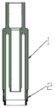
图3是本实用新型实施例玻璃吸嘴的结构示意图;3 is a schematic structural diagram of a glass suction nozzle according to an embodiment of the present invention;
图4是图3的内部结构图;Fig. 4 is the internal structure diagram of Fig. 3;
图5是本实用新型实施例雾化芯结构示意图;5 is a schematic structural diagram of an atomizing core according to an embodiment of the present invention;
图6是本图5的内部结构图;Fig. 6 is the internal structure diagram of this Fig. 5;
图7是本实用新型实施例的组装示意图;Fig. 7 is the assembly schematic diagram of the embodiment of the present invention;
图8是本实用新型实施例的基座部结构示意图;8 is a schematic structural diagram of a base portion of an embodiment of the present invention;
图9是本实用新型实施例的螺纹底座结构示意图;9 is a schematic view of the structure of a threaded base according to an embodiment of the present invention;
图10是本实用新型实施例的底座压件结构示意图;10 is a schematic structural diagram of a base pressing piece according to an embodiment of the present invention;
图11是本实用新型实施例的硅胶座结构示意图一;FIG. 11 is a first structural schematic diagram of a silicone seat according to an embodiment of the present invention;
图12是本实用新型实施例的硅胶座结构示意图二;Fig. 12 is the second structural schematic diagram of the silica gel seat according to the embodiment of the present invention;
图13是本实用新型实施例的硅胶座结构示意图三。FIG. 13 is a schematic diagram 3 of the structure of the silica gel seat according to the embodiment of the present invention.
图中:1、油杯部;101、吸嘴;102、油杯;103、通气管;104、外侧台阶;2、基座部;201、外螺纹;202、胶槽;203、定位凸槽;3、装饰圈;301、内螺纹;4、螺纹底座;401、进气孔;402、底座外螺纹;403、内孔台阶;404、侧壁;405、底座内孔;5、底座压件;501、三角形定位部;502、凹槽;503、中心内孔;6、电极;601、电极小头;7、硅胶座;701、环形密封圈;702、凸台;703、V形进油槽;704、进油孔;705、中间孔;8、绝缘圈;801、绝缘圈小头;9、陶瓷发热丝;901、多孔陶瓷;902、发热丝;903、引脚;10、吸油棉。In the figure: 1. Oil cup part; 101, suction nozzle; 102, oil cup; 103, ventilation pipe; 104, outer step; 2, base part; 201, external thread; 202, glue groove; 203, positioning convex groove ;3, decorative ring; 301, internal thread; 4, threaded base; 401, air inlet; 402, base external thread; 403, inner hole step; 404, side wall; 405, base inner hole; 5, base press ;501, triangular positioning part; 502, groove; 503, central inner hole; 6, electrode; 601, small electrode head; 7, silicone seat; 701, annular sealing ring; 702, boss; 703, V-shaped oil inlet ; 704, oil inlet; 705, middle hole; 8, insulating ring; 801, small end of insulating ring; 9, ceramic heating wire; 901, porous ceramic; 902, heating wire; 903, pin; 10, oil-absorbing cotton.
具体实施方式Detailed ways
下面以一个实施方式对本实用新型作进一步详细的说明,但应当说明,本实用新型的保护范围不仅仅限于此。The present utility model will be described in further detail below with an embodiment, but it should be noted that the protection scope of the present utility model is not limited to this.
如图1-13所示,本实用新型涉及医疗辅助和电子雾化领域,具体为一种全玻璃雾化器,包括玻璃吸嘴和雾化芯,所述玻璃吸嘴组件包括油杯部1和基座部2,所述油杯部1顶端设有吸嘴101,所述油杯部1的中间设有通气管103,所述通气管103与油杯部1一体成型,二者之间形成的空腔组成油杯102,所述吸嘴101、油杯102和通气管103为一体式玻璃结构。所述油杯部1底部外侧有一台阶104,所述油杯部1底部设有基座部2,所述基座部2设有外螺纹201,所述基座部2一端与油杯部1外侧台阶104用胶水固定连接,另一端与装饰圈3螺纹连接,所述基座部2与油杯部1连接的一端设有胶槽202,与装饰圈3连接的一端底部外侧设有外螺纹201、内侧设有定位凸槽203。As shown in Figures 1-13, the present utility model relates to the fields of medical assistance and electronic atomization, and in particular is an all-glass atomizer, comprising a glass suction nozzle and an atomizing core, and the glass suction nozzle assembly includes an oil cup portion 1 And the base part 2, the top of the oil cup part 1 is provided with a
所述雾化芯包括装饰圈3、螺纹底座4、底座压件5、硅胶座7、陶瓷发热丝9、吸油棉10、绝缘圈8和电极6;所述装饰圈3为内螺纹结构,所述装饰圈3与基座部2连接的一端设有内螺纹301;所述螺纹底座4为中空外螺纹结构,其中间设有底座内孔405,底部外侧设有底座外螺纹402,用于与外接电池连接,所述外螺纹402上方侧壁上设有对称进气孔401,螺纹底座内孔405下方设有内孔台阶403;所述底座压件5具有一中心内孔503,底座压件5上端外侧设有对称凸起三角形定位部501,所述凸起三角形定位部501两侧设有凹槽502,所述凸起三角形定位部501与基座部2内侧定位凸槽203错位对接,所述基座部2与底座压件5对接部分可活动旋转小于180度。The atomizing core includes a
所述装饰圈3套在螺纹底座4上用底座压件5夹装压住成活动环。The
所述硅胶座7采用中间通孔结构,其中间为中间孔705,外侧上方对称设有V形进油槽703,所述V形进油槽703上分别设有进油孔704直通中间孔705,所述硅胶座7外侧中间部分设有对称凸台702,所述V形进油槽703与凸台702中间设有环形密封圈701,所述硅胶座7装在底座压件5上,所述硅胶座7中间对称凸台702装入底座压件凹槽502内,所述硅胶座7装配后环形密封圈701与油杯部1呈密封状态,实现油杯内腔无金属接触。The
所述陶瓷发热丝9由多孔陶瓷901、发热丝902、引脚903构成,所述陶瓷发热丝9中间内置发热丝902,外露两根引脚903作为正负极,所述吸油棉10为长方形,所述陶瓷发热丝9外侧用吸油棉10包裹后装入硅胶座7中间孔705内,注入油杯102内腔的雾化烟油经进油孔704、吸油棉10导入陶瓷发热丝9内加热雾化。The
所述绝缘圈8装在螺纹底座4下方内孔台阶403上,所述电极6装入绝缘圈8内,所述发热丝引脚903一根与螺纹底座4导通,另一根引脚夹在绝缘圈8与电极6中间,与电池装配后形成电子回路工作时产生烟雾。The insulating
所述吸嘴101、通气管103、硅胶座7、底座压件5和螺纹底座4中间的中空部分形成进气雾化通道,使用吸食时雾化形成的烟雾从通道吸入口中。The
本实用新型在组装时,包括以下步骤:When the utility model is assembled, it comprises the following steps:
步骤1:将油杯部1安装于基座部2上,在基座部2的胶槽202内打胶,将油杯部1与基座部2固定;Step 1: Install the oil cup part 1 on the base part 2, apply glue in the
步骤2:先把硅胶座7装入底座压件5内,将硅胶座7外侧对称凸台702装入底座压件5的凹槽502内,装好后将V形进油槽703露在外面;Step 2: First, put the
步骤3:将长方形吸油棉10居中紧包在陶瓷发热丝9外侧,再将包好棉的陶瓷发热丝定位一体塞入硅胶座7中间通孔705内,安装时发热丝引脚903向底座压件5方向拉直;Step 3: Center the rectangular oil-absorbing
步骤4:螺纹底座4的外螺纹402朝下放入治具内,装饰圈3内螺纹301向下套入螺纹底座4中,将步骤3加工好组件的发热丝引脚903端向下穿过螺纹底座内孔405,将底座压件5内孔503压入螺纹底座4的侧壁404上压紧,压装完成后装饰圈3是活动的,螺纹底座4与步骤3组装后部件成紧配状态;Step 4: Put the
步骤5:将陶瓷发热丝9其中一根引脚903与螺纹底座4内孔403贴合,绝缘圈8小头801装入螺纹底座4内孔403处,陶瓷发热丝9另一根引脚903穿过绝缘圈8与内壁贴合,最后将电极6小头601装入绝缘圈8内孔中,陶瓷发热丝9的两根引脚903外露部分用剪钳剪平于产品上,不外露,陶瓷发热丝9的两根引脚903分别夹在绝缘圈8的内外壁绝缘,至此雾化芯组装完成;Step 5: Fit one of the
步骤6:将吸嘴101向下,基座部2向上放置注油,然后把雾化芯硅胶座7推入油杯102内,硅胶座7中孔套在通气管103外壁上密封,装饰圈3内螺纹301与吸嘴基座2上的外螺纹201对接顺时针旋紧,此时硅胶座7侧边的环形密封圈与吸嘴油仓内壁贴合密封,油从硅胶座7侧边的进油孔704流入吸油棉10上,最后导入陶瓷发热丝9中,产品装配后与电池形成电子回路,工作时产生烟雾即可吸食。Step 6: Put the
本实用新型油腔内部全玻璃加硅胶结构,无金属接触,注油装配后无重金属污染,注油方便,不漏油,不会因为注油后未及时装配密封产生漏油现象,自主创新的硅胶进油结构,确保不会因供油不畅导致雾化芯干烧或出现漏油,烟嘴与雾化芯定位防装卸锁死结构,装配到电池上易装易取,不会出现取不出来或油杯取出后底座卡在电池上的现象,可循环使用,具有外形美观、使用安全便捷、环保、注油方便、无重金属污染、口感纯正还原度高等优点。The oil cavity of the utility model has an all-glass and silica gel structure, no metal contact, no heavy metal pollution after oil injection and assembly, convenient oil injection, no oil leakage, and no oil leakage due to the failure to assemble and seal after oil injection. The structure ensures that the atomizing core will not dry out or leak oil due to poor oil supply. The cigarette holder and the atomizing core are positioned to prevent installation and removal. The phenomenon that the base is stuck on the battery after the cup is taken out can be recycled, and has the advantages of beautiful appearance, safe and convenient use, environmental protection, convenient oil filling, no heavy metal pollution, and high degree of pure reduction in taste.
虽然结合附图描述了本实用新型的实施方式,但是本领域的技术人员可以在所附权利要求的范围之内作出各种变形或修改,只要不超过本实用新型的权利要求所描述的保护范围,都应当在本实用新型的保护范围之内。Although the embodiments of the present invention are described in conjunction with the accompanying drawings, those skilled in the art can make various changes or modifications within the scope of the appended claims, as long as the protection scope described in the claims of the present invention is not exceeded , should be within the scope of protection of the present invention.
Claims (9)
Priority Applications (2)
| Application Number | Priority Date | Filing Date | Title |
|---|---|---|---|
| CN202020730938.XU CN212282439U (en) | 2020-05-06 | 2020-05-06 | An all-glass atomizer |
| US17/117,614 US10945455B1 (en) | 2020-05-06 | 2020-12-10 | Full glass atomizer |
Applications Claiming Priority (1)
| Application Number | Priority Date | Filing Date | Title |
|---|---|---|---|
| CN202020730938.XU CN212282439U (en) | 2020-05-06 | 2020-05-06 | An all-glass atomizer |
Publications (1)
| Publication Number | Publication Date |
|---|---|
| CN212282439U true CN212282439U (en) | 2021-01-05 |
Family
ID=73965725
Family Applications (1)
| Application Number | Title | Priority Date | Filing Date |
|---|---|---|---|
| CN202020730938.XU Withdrawn - After Issue CN212282439U (en) | 2020-05-06 | 2020-05-06 | An all-glass atomizer |
Country Status (2)
| Country | Link |
|---|---|
| US (1) | US10945455B1 (en) |
| CN (1) | CN212282439U (en) |
Cited By (2)
| Publication number | Priority date | Publication date | Assignee | Title |
|---|---|---|---|---|
| CN111544714A (en) * | 2020-05-06 | 2020-08-18 | 深圳市石开科技有限公司 | All-glass atomizer and manufacturing method thereof |
| CN115005500A (en) * | 2021-03-04 | 2022-09-06 | 布林克集团公司 | Vaporizer cartridge with removable ring |
Families Citing this family (7)
| Publication number | Priority date | Publication date | Assignee | Title |
|---|---|---|---|---|
| CN209449671U (en) * | 2018-12-03 | 2019-10-01 | 深圳市源格林科技有限公司 | A kind of new electronic cigarette |
| US11839239B2 (en) | 2020-08-12 | 2023-12-12 | DES Products Ltd. | Adjustable airflow cartridge for electronic vaporizer |
| CN113666763B (en) * | 2021-08-23 | 2023-06-23 | 深圳市安芯精密组件有限公司 | Atomizing core structural member and preparation method thereof |
| CN114948670B (en) * | 2022-04-28 | 2025-09-19 | 成都捷芯科技有限公司 | Atomizing device and handheld beauty instrument |
| WO2024119032A2 (en) * | 2022-12-02 | 2024-06-06 | Warehouse Goods LLC | Double filter vaporizer |
| CN222031475U (en) * | 2024-02-04 | 2024-11-22 | 派克斯创新(深圳)科技有限公司 | Electronic cigarette component |
| US20250120443A1 (en) * | 2023-10-11 | 2025-04-17 | Yibla (Usa) Technology Co., Ltd | Atomizing core with double heating structure and aerosol generating device |
Family Cites Families (81)
| Publication number | Priority date | Publication date | Assignee | Title |
|---|---|---|---|---|
| USD413002S (en) | 1997-11-03 | 1999-08-17 | Richard Melograno | Combined tobacco smoking pipe bowl and receiving stem |
| CN201830900U (en) | 2010-06-09 | 2011-05-18 | 李永海 | Tobacco juice atomization device for electronic cigarette |
| CN102326869B (en) | 2011-05-12 | 2013-04-03 | 陈志平 | Atomization nozzle of electronic atomization inhaler |
| CN202262413U (en) | 2011-09-05 | 2012-06-06 | 李永海 | Disposable electronic cigarette |
| USD688415S1 (en) | 2011-12-22 | 2013-08-20 | Needs Co., Ltd. | E-cigarette |
| CN102894485B (en) | 2012-10-23 | 2015-04-01 | 深圳市合元科技有限公司 | Atomization device for electronic cigarette as well as atomizer and electronic cigarette |
| CN102920028B (en) | 2012-11-15 | 2016-01-27 | 深圳市合元科技有限公司 | Atomizers for electronic cigarettes and electronic cigarettes |
| US9538788B2 (en) | 2013-03-15 | 2017-01-10 | Vapor Corp. | Electronic cigarette |
| USD724779S1 (en) | 2013-03-21 | 2015-03-17 | Kimree Hi-Tech Inc. | Electronic cigarette |
| WO2014146297A1 (en) | 2013-03-22 | 2014-09-25 | Liu Qiuming | Electronic cigarette |
| CN204579885U (en) | 2013-03-29 | 2015-08-26 | 惠州市吉瑞科技有限公司 | Electronic cigarette |
| CN203329913U (en) | 2013-05-07 | 2013-12-11 | 深圳市合元科技有限公司 | Electronic cigarette and atomizer with cotton |
| US20140376895A1 (en) * | 2013-06-19 | 2014-12-25 | Sihui Han | Dual-tube electronic cigarette atomizer |
| USD747545S1 (en) | 2013-07-12 | 2016-01-12 | Kimree Hi-Tech Inc | Atomizer |
| CN203555161U (en) | 2013-08-07 | 2014-04-23 | 深圳市合元科技有限公司 | Atomizer and electronic cigarette provided therewith |
| USD730571S1 (en) | 2013-10-14 | 2015-05-26 | Shenzhen Smoore Technology Limited | Electronic cigarette |
| US9345269B2 (en) | 2013-11-19 | 2016-05-24 | Tuanfang Liu | Electronic cigarette |
| US9497998B2 (en) * | 2013-12-03 | 2016-11-22 | Shenzhen Smoore Technology Limited | Electronic cigarette |
| CN203952431U (en) | 2014-05-23 | 2014-11-26 | 深圳市合元科技有限公司 | Atomizer and electronic cigarette for electronic cigarette |
| US9380811B2 (en) | 2014-03-11 | 2016-07-05 | Henry Chung | Wet scrubbing electronic cigarette |
| US20150272218A1 (en) | 2014-03-27 | 2015-10-01 | Shenzhen Smoore Technology Limited | Electronic cigarette |
| USD724264S1 (en) | 2014-04-02 | 2015-03-10 | Michael Chen | Electronic cigarette |
| CN203986095U (en) | 2014-04-03 | 2014-12-10 | 惠州市吉瑞科技有限公司 | A kind of atomizer and electronic cigarette |
| USD752279S1 (en) | 2014-07-02 | 2016-03-22 | Huizhou Kimree Technology Co., Ltd. | Electronic cigarette |
| US9661878B2 (en) | 2014-07-03 | 2017-05-30 | Tuanfang Liu | Electronic cigarette |
| CN204070542U (en) | 2014-07-11 | 2015-01-07 | 深圳市合元科技有限公司 | Atomising device and electronic cigarette |
| WO2016011574A1 (en) * | 2014-07-21 | 2016-01-28 | 惠州市吉瑞科技有限公司 | Electronic cigarette |
| USD778492S1 (en) | 2014-08-20 | 2017-02-07 | Huizhou Kimree Technology Co., Ltd | Atomizer |
| USD769519S1 (en) | 2014-09-25 | 2016-10-18 | Shenzhen Smoore Technology Limited | Electronic cigarette cartridge |
| USD774247S1 (en) | 2014-09-25 | 2016-12-13 | Shenzhen Smoore Technology Limited | Electronic cigarette |
| USD749261S1 (en) | 2014-10-14 | 2016-02-09 | Shenzhen Smoore Technology Limited | Electronic cigarette atomizer |
| CA162242S (en) | 2014-11-28 | 2016-05-27 | Huizhou Kimree Technology Co Ltd | Electronic cigarette atomizer |
| CN204499488U (en) | 2015-04-07 | 2015-07-29 | 刘团芳 | The adjustable atomizer of a kind of cigarette holder air-flow |
| US10383368B2 (en) | 2015-07-06 | 2019-08-20 | Michael Raymond Larson | Atypical vaporizing apparatus |
| US10869502B2 (en) | 2015-07-31 | 2020-12-22 | 14Th Round Inc. | Disposable assembly for vaporizing e-liquid and a method of using the same |
| EP3127441B1 (en) | 2015-08-06 | 2018-12-05 | Fontem Holdings 1 B.V. | Electronic smoking device with a glass capillary tube |
| DE102015113124A1 (en) | 2015-08-10 | 2017-02-16 | Schott Ag | Open-pore sintered glasses for use in electronic cigarettes |
| USD828623S1 (en) | 2015-09-25 | 2018-09-11 | Avanzato Technology Corp. | Foil tank |
| EP3162227B1 (en) | 2015-10-28 | 2023-07-12 | Fontem Ventures B.V. | Electronic smoking device, cartomizer and liquid reservoir |
| USD827152S1 (en) | 2016-01-21 | 2018-08-28 | R.Y.L. Inc. | Disposable vial |
| USD897840S1 (en) | 2016-01-21 | 2020-10-06 | Pacific Vial Mfg., Inc. | Glass tip |
| US10512281B2 (en) * | 2016-01-21 | 2019-12-24 | R.Y.L. Inc. | Method of making a disposable vial for packing tobacco to be smoked |
| KR20170102415A (en) | 2016-01-26 | 2017-09-11 | 시아오춘 주 | Ceramic vaporizer with replaceable e-liquid storage medium and electronic cigarettes having the same |
| USD800381S1 (en) | 2016-01-28 | 2017-10-17 | Shenzhen Smoore Technology Limited | Atomizer for electronic cigarettes |
| WO2017139762A1 (en) | 2016-02-12 | 2017-08-17 | Alexander Gadas | Modular vaporizer |
| US9801418B1 (en) | 2016-04-27 | 2017-10-31 | Tuanfang Liu | Electronic cigarette |
| USD817543S1 (en) | 2016-08-01 | 2018-05-08 | Tuanfang Liu | Atomizer of electronic cigarette |
| CN107752129B (en) | 2016-08-19 | 2024-04-23 | 湖南中烟工业有限责任公司 | Ultrasonic atomization sheet and manufacturing method thereof, ultrasonic atomizer and electronic cigarette |
| CN106490686B (en) | 2016-11-23 | 2024-06-18 | 深圳市合元科技有限公司 | Smoke generator, electronic cigarette and detachable atomizing device |
| USD849318S1 (en) | 2016-12-29 | 2019-05-21 | Shenzhen First Union Technology Co., Ltd. | Atomizer for electronic cigarette |
| USD853635S1 (en) | 2017-02-23 | 2019-07-09 | Shenzhen Smoore Technology Limited | Atomizer for electronic cigarette |
| USD825834S1 (en) | 2017-03-13 | 2018-08-14 | Shenzhen Smoore Technology Limited | Electronic cigarette |
| USD849317S1 (en) | 2017-05-31 | 2019-05-21 | Joyetech Europe Holding Gmbh | Smoking device |
| CN107167239B (en) * | 2017-07-01 | 2018-11-30 | 北京曙光明电子光源仪器有限公司 | A kind of glass atomizer and its manufacturing method |
| CN207185908U (en) | 2017-08-02 | 2018-04-06 | 刘团芳 | A kind of vertical more heating coil atomizers |
| USD836243S1 (en) | 2017-08-15 | 2018-12-18 | Tuanfang Liu | E-cigarette atomizer |
| USD826471S1 (en) | 2017-08-18 | 2018-08-21 | Shenzhen Smoore Technology Limited | Electronic atomizer |
| USD877975S1 (en) | 2017-10-28 | 2020-03-10 | Vuber Technologies, Inc. | Atomizer |
| USD863666S1 (en) | 2017-11-10 | 2019-10-15 | Boulder (Shenzhen) Technologies, Inc | Electronic cigarette |
| USD861978S1 (en) | 2018-01-02 | 2019-10-01 | Shenzhen Smoore Technology Limited | Electronic cigarette atomizer |
| USD875306S1 (en) | 2018-01-19 | 2020-02-11 | Shenzhen Smoore Technology Limited | Electronic cigarette |
| CN208080545U (en) | 2018-04-10 | 2018-11-13 | 深圳市源格林科技有限公司 | A kind of new electronic cigarette |
| CA182663S (en) | 2018-04-23 | 2020-03-02 | Shenzhen Ivps Tech Co Ltd | Electronic cigarette |
| USD869753S1 (en) | 2018-05-02 | 2019-12-10 | Li Yang | Telescopic tobacco pipe |
| WO2019222498A1 (en) | 2018-05-16 | 2019-11-21 | Intrepid Brands, LLC | High temperature resistant glass coatings for metallic coils |
| CN208875406U (en) | 2018-07-17 | 2019-05-21 | 深圳市合元科技有限公司 | Atomizer and electronic cigarette |
| USD883567S1 (en) | 2018-08-15 | 2020-05-05 | Shenzhen Smoore Technology Limited | Atomizer for electronic cigarette |
| USD894478S1 (en) | 2018-09-07 | 2020-08-25 | 14Th Round Inc. | Vaporizer |
| USD885653S1 (en) | 2018-11-21 | 2020-05-26 | Ald Group Limited | Electronic cigarette |
| CN209449671U (en) | 2018-12-03 | 2019-10-01 | 深圳市源格林科技有限公司 | A kind of new electronic cigarette |
| US11076643B2 (en) | 2018-12-10 | 2021-08-03 | Tuanfang Liu | Electronic cigarette having reliably sealed e-liquid inlet |
| US11071328B2 (en) | 2018-12-18 | 2021-07-27 | Tuanfang Liu | Electronic cigarette |
| USD899677S1 (en) | 2018-12-19 | 2020-10-20 | Tuanfang Liu | Electronic cigarette |
| USD898993S1 (en) | 2018-12-30 | 2020-10-13 | Shenzhen Smoore Technology Limited | Atomizer of electronic cigarette |
| USD893798S1 (en) | 2019-01-22 | 2020-08-18 | Tuanfang Liu | Electronic cigarette |
| USD892398S1 (en) | 2019-03-07 | 2020-08-04 | Ygreen Inc. | Electronic cigarette |
| CN210017878U (en) | 2019-03-20 | 2020-02-07 | 深圳市启慕德科技有限公司 | Glass atomizing core for electronic cigarette |
| CN209983524U (en) | 2019-04-02 | 2020-01-24 | 深圳市绿烟科技有限公司 | Double-layer quartz glass heating device |
| US11298474B2 (en) | 2019-04-02 | 2022-04-12 | Tuanfang Liu | Electronic cigarette |
| US20200315258A1 (en) | 2019-04-05 | 2020-10-08 | Ygreen Inc. | Electronic cigarette and method for manufacturing component thereof |
| USD900387S1 (en) | 2019-05-24 | 2020-10-27 | Tuanfang Liu | Electronic cigarette |
-
2020
- 2020-05-06 CN CN202020730938.XU patent/CN212282439U/en not_active Withdrawn - After Issue
- 2020-12-10 US US17/117,614 patent/US10945455B1/en active Active - Reinstated
Cited By (4)
| Publication number | Priority date | Publication date | Assignee | Title |
|---|---|---|---|---|
| CN111544714A (en) * | 2020-05-06 | 2020-08-18 | 深圳市石开科技有限公司 | All-glass atomizer and manufacturing method thereof |
| CN111544714B (en) * | 2020-05-06 | 2025-03-14 | 东莞市石开科技有限公司 | All-glass atomizer and manufacturing method thereof |
| CN115005500A (en) * | 2021-03-04 | 2022-09-06 | 布林克集团公司 | Vaporizer cartridge with removable ring |
| CN115005500B (en) * | 2021-03-04 | 2023-12-08 | 布林克集团公司 | Vaporizer cartridge with removable ring |
Also Published As
| Publication number | Publication date |
|---|---|
| US20210084979A1 (en) | 2021-03-25 |
| US10945455B1 (en) | 2021-03-16 |
Similar Documents
| Publication | Publication Date | Title |
|---|---|---|
| CN212282439U (en) | An all-glass atomizer | |
| CN111544714B (en) | All-glass atomizer and manufacturing method thereof | |
| CN211746949U (en) | Nebulizer and aerosol generating device | |
| CN205196997U (en) | A reservoir and atomizer and electron cigarette for electron cigarette | |
| CN102920028B (en) | Atomizers for electronic cigarettes and electronic cigarettes | |
| US20110303231A1 (en) | Tobacco Solution Atomizing Device For Electronic Cigarette | |
| CN204579895U (en) | Light heating secondary-atomizing Nebulizer for electronic cigarette and electronic cigarette | |
| CN205757214U (en) | A kind of atomization core and nebulizer thereof | |
| WO2016119273A1 (en) | Packaging structure of electronic cigarette oil | |
| WO2018000469A1 (en) | Combination-type ultrasonic atomizer and atomizing method therefor, electronic cigarette | |
| CN105996134A (en) | Upwards-outlet core electronic cigarette atomizer with pressure screw cap | |
| CN206866632U (en) | Atomising device and electronic cigarette | |
| CN111567882B (en) | Electronic cigarette atomizer and electronic cigarette | |
| CN211672447U (en) | Electronic cigarette atomizer and electronic cigarette | |
| CN215303014U (en) | An electronic cigarette oil leakage prevention structure | |
| CN212212696U (en) | Atomizer and electronic atomization device | |
| CN204796753U (en) | Electronic smoke device | |
| CN218126965U (en) | Electronic cigarette atomizer for solid e-juice | |
| CN210114048U (en) | Electronic cigarette atomizing core and atomizer | |
| CN215873448U (en) | Disposable two oil storehouse electronic atomization wares | |
| CN108260854B (en) | Electronic cigarette and atomization device thereof | |
| CN205962843U (en) | A rump electron smog spinning disk atomiser of going up of spiral cover is pressed in area | |
| CN111436660A (en) | Child lock atomizer and electronic cigarette | |
| CN209403573U (en) | Oil-leakage-proof electronic cigarette atomizer and electronic cigarette | |
| CN215684877U (en) | Atomizer easy to inject liquid |
Legal Events
| Date | Code | Title | Description |
|---|---|---|---|
| GR01 | Patent grant | ||
| GR01 | Patent grant | ||
| CB03 | Change of inventor or designer information |
Inventor after: Wang Shenyi Inventor after: Zhong Ning Inventor before: Wang Shenyi |
|
| CB03 | Change of inventor or designer information | ||
| AV01 | Patent right actively abandoned |
Granted publication date: 20210105 Effective date of abandoning: 20250314 |
|
| AV01 | Patent right actively abandoned |
Granted publication date: 20210105 Effective date of abandoning: 20250314 |
|
| AV01 | Patent right actively abandoned | ||
| AV01 | Patent right actively abandoned |