CN211856397U - Label detection and positioning device and its label manufacturing equipment - Google Patents
Label detection and positioning device and its label manufacturing equipment Download PDFInfo
- Publication number
- CN211856397U CN211856397U CN201922010061.7U CN201922010061U CN211856397U CN 211856397 U CN211856397 U CN 211856397U CN 201922010061 U CN201922010061 U CN 201922010061U CN 211856397 U CN211856397 U CN 211856397U
- Authority
- CN
- China
- Prior art keywords
- label
- label detection
- detection
- positioning
- plate
- Prior art date
- Legal status (The legal status is an assumption and is not a legal conclusion. Google has not performed a legal analysis and makes no representation as to the accuracy of the status listed.)
- Expired - Fee Related
Links
- 238000001514 detection method Methods 0.000 title claims abstract description 261
- 238000004519 manufacturing process Methods 0.000 title claims abstract description 42
- 238000006073 displacement reaction Methods 0.000 claims abstract description 41
- 238000003384 imaging method Methods 0.000 claims abstract description 13
- 238000005520 cutting process Methods 0.000 claims description 146
- 239000000463 material Substances 0.000 claims description 38
- 238000012546 transfer Methods 0.000 claims description 13
- 229920001296 polysiloxane Polymers 0.000 claims description 7
- 230000007246 mechanism Effects 0.000 claims description 3
- 238000007711 solidification Methods 0.000 claims 2
- 230000008023 solidification Effects 0.000 claims 2
- 238000003848 UV Light-Curing Methods 0.000 description 107
- 239000003292 glue Substances 0.000 description 52
- 239000010410 layer Substances 0.000 description 34
- 238000001179 sorption measurement Methods 0.000 description 32
- 238000012545 processing Methods 0.000 description 31
- 230000005540 biological transmission Effects 0.000 description 24
- 238000002360 preparation method Methods 0.000 description 21
- 238000003825 pressing Methods 0.000 description 20
- 238000000034 method Methods 0.000 description 19
- 238000009434 installation Methods 0.000 description 17
- 230000008569 process Effects 0.000 description 14
- 238000003860 storage Methods 0.000 description 14
- 230000017525 heat dissipation Effects 0.000 description 13
- 238000010586 diagram Methods 0.000 description 11
- 238000001723 curing Methods 0.000 description 4
- 230000000694 effects Effects 0.000 description 4
- 238000002955 isolation Methods 0.000 description 4
- 239000011241 protective layer Substances 0.000 description 3
- 230000001360 synchronised effect Effects 0.000 description 3
- VYPSYNLAJGMNEJ-UHFFFAOYSA-N Silicium dioxide Chemical group O=[Si]=O VYPSYNLAJGMNEJ-UHFFFAOYSA-N 0.000 description 2
- 230000003139 buffering effect Effects 0.000 description 2
- 238000011161 development Methods 0.000 description 2
- 230000014509 gene expression Effects 0.000 description 2
- 238000002372 labelling Methods 0.000 description 2
- 238000003754 machining Methods 0.000 description 2
- 238000005192 partition Methods 0.000 description 2
- 239000000741 silica gel Substances 0.000 description 2
- 229910002027 silica gel Inorganic materials 0.000 description 2
- NIXOWILDQLNWCW-UHFFFAOYSA-N acrylic acid group Chemical group C(C=C)(=O)O NIXOWILDQLNWCW-UHFFFAOYSA-N 0.000 description 1
- 239000012790 adhesive layer Substances 0.000 description 1
- 208000003464 asthenopia Diseases 0.000 description 1
- 239000011324 bead Substances 0.000 description 1
- 230000007812 deficiency Effects 0.000 description 1
- 230000002950 deficient Effects 0.000 description 1
- 238000007599 discharging Methods 0.000 description 1
- 238000009826 distribution Methods 0.000 description 1
- 238000005516 engineering process Methods 0.000 description 1
- 239000012530 fluid Substances 0.000 description 1
- 238000010330 laser marking Methods 0.000 description 1
- 230000007774 longterm Effects 0.000 description 1
- 239000003550 marker Substances 0.000 description 1
- 239000012528 membrane Substances 0.000 description 1
- 238000012986 modification Methods 0.000 description 1
- 230000004048 modification Effects 0.000 description 1
- 239000002245 particle Substances 0.000 description 1
- 238000007639 printing Methods 0.000 description 1
- 238000006748 scratching Methods 0.000 description 1
- 230000002393 scratching effect Effects 0.000 description 1
Images




Landscapes
- Labeling Devices (AREA)
Abstract
一种标签检测定位装置及其标签制造设备,标签检测定位装置,包括:标签检测调节组件、标签检测横向位移组件、标签检测升降定位组件及标签检测组件,标签检测调节组件包括标签检测调节底座、标签检测调节滑板及标签检测调节驱动件,标签检测横向位移组件包括标签检测横向定位杆、标签检测横向位移滑板及标签检测横向驱动件,标签检测升降定位组件包括标签检测升降驱动件、标签检测升降板及标签检测定位板,标签检测组件包括标签检测安装板及多标签检测成像件。本实用新型的标签检测定位装置通过设置标签检测调节组件、标签检测横向位移组件、标签检测升降定位组件及标签检测组件,从而能够对标签结构进行快速定位及检测。

A label detection and positioning device and its label manufacturing equipment, the label detection and positioning device, comprising: a label detection adjustment component, a label detection lateral displacement component, a label detection lift positioning component and a label detection component, the label detection adjustment component includes a label detection adjustment base, Label detection adjustment slide and label detection adjustment drive, label detection lateral displacement assembly includes label detection lateral positioning rod, label detection lateral displacement slide and label detection lateral drive, label detection lift positioning assembly includes label detection lift drive, label detection lift Plate and label detection positioning plate, label detection components include label detection mounting plate and multi-label detection imaging parts. The label detection and positioning device of the utility model is provided with a label detection adjustment component, a label detection lateral displacement component, a label detection lift positioning component and a label detection component, so that the label structure can be quickly positioned and detected.
Description
技术领域technical field
本发明涉及标签加工技术领域,特别是涉及一种标签检测定位装置。The invention relates to the technical field of label processing, in particular to a label detection and positioning device.
背景技术Background technique
随着经济的发展,标签在商品上应用广泛,带动了标签印刷业的飞速发展。在一些电子产品应用中,往往会将防爆膜制作成标签贴附在对应的电子产品上,这样不但能够对电子产品进行保护,还能够起到对品牌的宣传及推广的作用。With the development of economy, labels are widely used in commodities, which has led to the rapid development of label printing industry. In some electronic product applications, the explosion-proof film is often made into a label and attached to the corresponding electronic product, which can not only protect the electronic product, but also play a role in brand promotion and promotion.
在标签结构的加工工艺中,需要对标签结构的表面进行检测,从而将具有裂缝、颗粒物或者刮痕等不良品挑选出来。现有的检测方式一般采用人工肉眼的方式进行检测挑选,显然,人工的检测方式不但生产效率不高,而且容易在长时间工作后出现视觉疲劳,由此出现漏检或错检的情况,从而导致检测精度不高。In the processing technology of the label structure, the surface of the label structure needs to be inspected, so as to select defective products such as cracks, particles or scratches. The existing detection methods generally use artificial eyes for detection and selection. Obviously, the manual detection method not only has low production efficiency, but also is prone to visual fatigue after long-term work, resulting in missed or wrong detection. The detection accuracy is not high.
发明内容SUMMARY OF THE INVENTION
本发明的目的是克服现有技术中的不足之处,提供一种能够对标签结构进行快速定位及检测,且能够提高生产效率及加工质量的标签检测定位装置。The purpose of the present invention is to overcome the deficiencies in the prior art, and to provide a label detection and positioning device that can quickly locate and detect the label structure, and can improve production efficiency and processing quality.
本发明的目的是通过以下技术方案来实现的:The purpose of this invention is to realize through the following technical solutions:
一种标签检测定位装置,包括:A label detection and positioning device, comprising:
标签检测调节组件,标签检测调节组件包括标签检测调节底座、标签检测调节滑板及标签检测调节驱动件,所述标签检测调节底座上开设有标签检测调节滑槽,所述标签检测调节滑板上设置有标签检测调节滑动卡块,所述标签检测调节滑板滑动设置于所述标签检测调节底座上,且所述标签检测调节滑动卡块与所述标签检测调节滑槽连接,所述标签检测调节驱动件与所述标签检测调节滑板连接;The label detection and adjustment assembly includes a label detection and adjustment base, a label detection and adjustment slide and a label detection and adjustment drive. The label detection and adjustment base is provided with a label detection and adjustment chute, and the label detection and adjustment slide is provided with a Label detection and adjustment sliding block, the label detection and adjustment sliding plate is slidably arranged on the label detection and adjustment base, and the label detection and adjustment sliding block is connected with the label detection and adjustment chute, and the label detection and adjustment driver is connected with the label detection and adjustment slide plate;
标签检测横向位移组件,所述标签检测横向位移组件包括标签检测横向定位杆、标签检测横向位移滑板及标签检测横向驱动件,所述标签检测横向定位杆设置于所述标签检测调节滑板上,所述标签检测横向位移滑板滑动设置于所述标签检测横向定位杆上,所述标签检测横向驱动件与所述标签检测横向位移滑板连接;Label detection lateral displacement assembly, the label detection lateral displacement assembly includes a label detection lateral positioning rod, a label detection lateral displacement slide plate and a label detection lateral drive member, the label detection lateral positioning rod is arranged on the label detection adjustment slide, so The label detection lateral displacement slide plate is slidably arranged on the label detection lateral positioning rod, and the label detection lateral drive member is connected with the label detection lateral displacement slide plate;
标签检测升降定位组件,所述标签检测升降定位组件包括标签检测升降驱动件、标签检测升降板及标签检测定位板,所述标签检测升降驱动件设置于所述标签检测横向位移滑板上,所述标签检测升降板与所述标签检测升降驱动件连接,所述标签检测定位板设置于所述标签检测升降板上,所述标签检测定位板上开设有矩形定位孔,所述矩形定位孔的内侧壁上设置有定位缓冲层;及Label detection lift positioning assembly, the label detection lift positioning assembly includes a label detection lift drive, a label detection lift plate and a label detection positioning plate, the label detection lift drive is arranged on the label detection lateral displacement slide plate, the label detection lift The label detection lifting plate is connected with the label detection lifting driving member, the label detection positioning plate is arranged on the label detection lifting plate, the label detection positioning plate is provided with a rectangular positioning hole, and the inner side of the rectangular positioning hole is a positioning buffer layer is provided on the wall; and
标签检测组件,所述标签检测组件包括标签检测安装板及多个标签检测成像件,所述签检测安装板设置于所述标签检测升降板远离所述标签检测定位板的一端,各所述标签检测成像件间隔设置于所述标签检测安装板上,且各所述标签检测成像件分别位于所述矩形定位孔的上方。Label detection assembly, the label detection assembly includes a label detection mounting plate and a plurality of label detection imaging parts, the label detection mounting plate is arranged at the end of the label detection lifting plate away from the label detection positioning plate, and each label The detection imaging members are arranged on the label detection mounting plate at intervals, and each of the label detection imaging members is respectively located above the rectangular positioning hole.
在其中一个实施例中,所述标签检测调节滑槽的横截面为长方体结构。In one embodiment, the cross section of the label detection adjusting chute is a rectangular parallelepiped structure.
在其中一个实施例中,所述标签检测调节滑槽设置有两个。In one of the embodiments, the label detection and adjustment chute is provided with two.
在其中一个实施例中,两个所述标签检测调节滑槽相平行设置。In one of the embodiments, two of the label detection and adjustment chute are arranged in parallel.
在其中一个实施例中,所述标签检测调节驱动件为电机丝杆调节结构。In one of the embodiments, the label detection and adjustment drive member is a motor screw adjustment structure.
在其中一个实施例中,所述标签检测横向驱动件为伺服电机丝杆调节结构。In one of the embodiments, the label detection transverse drive member is a servo motor screw adjustment structure.
在其中一个实施例中,所述标签检测升降驱动件为升降气缸。In one of the embodiments, the label detection lift driving member is a lift cylinder.
在其中一个实施例中,所述定位缓冲层为硅胶缓冲层。In one embodiment, the positioning buffer layer is a silicone buffer layer.
在其中一个实施例中,所述标签检测安装板为长方体结构。In one of the embodiments, the label detection mounting plate has a rectangular parallelepiped structure.
一种标签制造设备,包括上述的标签检测定位装置,所述标签制造设备还包括工作台、上料传送装置、UV固化装置、标签打标装置、标签检测定位装置、标签切割装置及标签下料装置,所述上料传送装置设置于所述工作台上,所述 UV固化装置与所述上料传送装置连接,所述标签打标装置、所述标签检测定位装置、所述标签切割装置及所述标签下料装置沿所述上料传送装置的传送方向顺序设置于所述工作台上。A label manufacturing equipment, including the above-mentioned label detection and positioning device, the label manufacturing equipment also includes a workbench, a feeding and conveying device, a UV curing device, a label marking device, a label detection and positioning device, a label cutting device and a label blanking device The feeding and conveying device is arranged on the worktable, the UV curing device is connected to the feeding and conveying device, the label marking device, the label detection and positioning device, the label cutting device and the The label unloading device is sequentially arranged on the worktable along the conveying direction of the feeding conveying device.
与现有技术相比,本发明至少具有以下优点:Compared with the prior art, the present invention has at least the following advantages:
本发明的标签检测定位装置通过设置标签检测调节组件、标签检测横向位移组件、标签检测升降定位组件及标签检测组件,从而能够对标签结构进行快速定位及检测,由此代替人工的检测方式,使得生产效率及加工质量得到提高。The label detection and positioning device of the present invention can quickly locate and detect the label structure by setting a label detection adjustment component, a label detection lateral displacement component, a label detection lift positioning component and a label detection component, thereby replacing the manual detection method, so that Production efficiency and processing quality are improved.
附图说明Description of drawings
为了更清楚地说明本发明实施例的技术方案,下面将对实施例中所需要使用的附图作简单地介绍,应当理解,以下附图仅示出了本发明的某些实施例,因此不应被看作是对范围的限定,对于本领域普通技术人员来讲,在不付出创造性劳动的前提下,还可以根据这些附图获得其他相关的附图。In order to illustrate the technical solutions of the embodiments of the present invention more clearly, the following briefly introduces the accompanying drawings used in the embodiments. It should be understood that the following drawings only show some embodiments of the present invention, and therefore do not It should be regarded as a limitation of the scope, and for those of ordinary skill in the art, other related drawings can also be obtained according to these drawings without any creative effort.
图1为一种防爆膜标签的结构示意图;Fig. 1 is the structural representation of a kind of explosion-proof membrane label;
图2为本发明一实施方式的标签制造设备的结构示意图;2 is a schematic structural diagram of a label manufacturing apparatus according to an embodiment of the present invention;
图3为图1中的标签制造设备的上料传送装置的结构示意图;Fig. 3 is the structural representation of the feeding conveying device of the label manufacturing equipment in Fig. 1;
图4为图3中的上料传送装置的另一视角的结构示意图;FIG. 4 is a schematic structural diagram of the feeding and conveying device in FIG. 3 from another perspective;
图5为图1中的标签制造设备的UV固化装置的结构示意图;Fig. 5 is the structural representation of the UV curing device of the label manufacturing equipment in Fig. 1;
图6为图5中的UV固化装置的另一视角的结构示意图;6 is a schematic structural diagram of the UV curing device in FIG. 5 from another perspective;
图7为图1中的标签制造设备的标签打标装置的结构示意图;Fig. 7 is the structural representation of the label marking device of the label manufacturing equipment in Fig. 1;
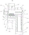
图8为图1中的标签制造设备的标签检测定位装置的结构示意图;8 is a schematic structural diagram of a label detection and positioning device of the label manufacturing equipment in FIG. 1;
图9为图1中的标签制造设备的标签切割装置的结构示意图;9 is a schematic structural diagram of a label cutting device of the label manufacturing equipment in FIG. 1;
图10为图9的标签切割装置的另一视角的结构示意图;10 is a schematic structural diagram of the label cutting device of FIG. 9 from another perspective;
图11为图1中的标签制造设备的标签点胶装置的结构示意图;11 is a schematic structural diagram of a label dispensing device of the label manufacturing equipment in FIG. 1;
图12为图11中的标签点胶装置的标点胶组件的结构示意图;12 is a schematic structural diagram of a punctuation glue assembly of the label glue dispensing device in FIG. 11;
图13为图1中的标签制造设备的标签圆环安装装置的结构示意图;13 is a schematic structural diagram of a label ring mounting device of the label manufacturing equipment in FIG. 1;
图14为图1中的标签制造设备的标签下料装置的结构示意图;14 is a schematic structural diagram of a label blanking device of the label manufacturing equipment in FIG. 1;
图15为图1中的标签下料装置的搬运安装组件、搬运夹紧件及搬运吸附组件的结构示意图。FIG. 15 is a schematic structural diagram of the transport installation component, the transport clamp and the transport adsorption component of the label cutting device in FIG. 1 .
具体实施方式Detailed ways
为了便于理解本发明,下面将参照相关附图对本发明进行更全面的描述。附图中给出了本发明的较佳实施方式。但是,本发明可以以许多不同的形式来实现,并不限于本文所描述的实施方式。相反地,提供这些实施方式的目的是使对本发明的公开内容理解的更加透彻全面。In order to facilitate understanding of the present invention, the present invention will be described more fully hereinafter with reference to the related drawings. The preferred embodiments of the invention are shown in the accompanying drawings. However, the present invention may be embodied in many different forms and is not limited to the embodiments described herein. Rather, these embodiments are provided so that a thorough and complete understanding of the present disclosure is provided.
需要说明的是,当元件被称为“固定于”另一个元件,它可以直接在另一个元件上或者也可以存在居中的元件。当一个元件被认为是“连接”另一个元件,它可以是直接连接到另一个元件或者可能同时存在居中元件。本文所使用的术语“垂直的”、“水平的”、“左”、“右”以及类似的表述只是为了说明的目的,并不表示是唯一的实施方式。It should be noted that when an element is referred to as being "fixed to" another element, it can be directly on the other element or intervening elements may also be present. When an element is referred to as being "connected" to another element, it can be directly connected to the other element or intervening elements may also be present. The terms "vertical", "horizontal", "left", "right" and similar expressions used herein are for the purpose of illustration only and do not represent the only embodiment.
除非另有定义,本文所使用的所有的技术和科学术语与属于本发明的技术领域的技术人员通常理解的含义相同。本文中在本发明的说明书中所使用的术语只是为了描述具体的实施方式的目的,不是旨在于限制本发明。本文所使用的术语“及/或”包括一个或多个相关的所列项目的任意的和所有的组合。Unless otherwise defined, all technical and scientific terms used herein have the same meaning as commonly understood by one of ordinary skill in the art to which this invention belongs. The terms used herein in the description of the present invention are for the purpose of describing specific embodiments only, and are not intended to limit the present invention. As used herein, the term "and/or" includes any and all combinations of one or more of the associated listed items.
需要说明的是,本文所使用关于元件与另一个元件“连接”的相关表述,也表示元件与另一个元件“连通”,流体可以在两者之间进行交换连通。It should be noted that, the relevant expressions about an element being "connected" with another element used herein also mean that an element is "communicating" with another element, and fluid can be exchanged and communicated between the two elements.
为了更好地对上述标签检测定位装置进行说明,将上述标签检测定位装置应用在如图1所示的种防爆膜标签及标签制造设备中进行说明,以更好地理解上述标签检测定位装置的构思。如图1所示,防爆膜标签10包括承载底板11、设置在所述承载底板11上的隔离层12及设置在所述隔离层12上的标签膜组13。为了便于防爆膜标签10的生产输送及加强其结构强度,承载底板11内部设置有多个磁性柱11a,如此,不但能够提高结构强度,而且能够通过磁性力使得防爆膜标签10在加工过程中不会轻易发生位置偏移;为了进一步提高防爆膜标签 10的结构强度及加工稳定性,承载底板11的两侧面上设置有配置卡块11b,两个配置卡块11b的底部延伸至承载底板11的底面,从而能够在加工时起到定位的作用。In order to better describe the above-mentioned label detection and positioning device, the above-mentioned label detection and positioning device is applied to the explosion-proof film label and label manufacturing equipment as shown in FIG. idea. As shown in FIG. 1 , the explosion-
请参阅图2,一种标签制造设备20,包括:工作台100、上料传送装置200、 UV固化装置300、标签打标装置400、标签检测定位装置500、标签切割装置 600、标签点胶装置700、标签圆环安装装置800及标签下料装置900,上料传送装置200设置于工作台100上,UV固化装置300与上料传送装置200连接,标签打标装置400、标签检测定位装置500、标签切割装置600、标签点胶装置 700、标签圆环安装装置800及标签下料装置900沿上料传送装置200的传送方向顺序设置于工作台100上。Referring to FIG. 2, a
需要说明的是,上料传送装置200用于将标签顺序传送至UV固化装置300、标签打标装置400、标签检测定位装置500、标签切割装置600、标签点胶装置 700、标签圆环安装装置800及标签下料装置900上;UV固化装置300用于对标签进行UV固化操作;标签打标装置400用于对标签进行打标操作;标签检测定位装置500用于对标签进行成像检测;标签切割装置600用于对标签进行切割操作;标签点胶装置700用于对标签进行点胶操作;标签圆环安装装置800 用于对标签进行圆环安装操作;标签下料装置900用于对标签进行下料操作;具体的,防爆膜标签10通过人工或对应的机械手放置在上料传送装置200上,通过上料传送装置200的传送操作,使得防爆膜标签10能够顺序经过UV固化装置300、标签打标装置400、标签检测定位装置500、标签切割装置600及标签下料装置900处进行相对应的加工操作;当上料传送装置200将防爆膜标签 10传送至UV固化装置300处时,UV固化装置300对上料传送装置200上的防爆膜标签10进行UV固化操作;当上料传送装置200将防爆膜标签10传送至标签打标装置400处时,标签打标装置400对上料传送装置200上的防爆膜标签10进行标签打标操作;当料传送装置200将防爆膜标签10传送至标签检测定位装置500处时,标签检测定位装置500对上料传送装置200上的防爆膜标签10进行CCD成像检测;当料传送装置200将防爆膜标签10传送至标签切割装置600处时,标签切割装置600对上料传送装置200上的防爆膜标签10进行标签切割操作;当料传送装置200将防爆膜标签10传送至标签下料装置900处时,标签下料装置900对上料传送装置200上的防爆膜标签10进行下料操作。It should be noted that the feeding and conveying
请再次参阅图2,工作台100包括机箱110及承载面板120,承载面板120 设置于机箱110的顶部,承载面板120上设置有传送区,承载面板120的表面设置有缓冲胶层。Referring to FIG. 2 again, the
需要说明的是,机箱110的底部设置有多个移动轮,如此,能够便于标签制造设备20的移动放置;承载面板120用于承载固定上料传送装置200、UV固化装置300、标签打标装置400、标签检测定位装置500、标签切割装置600及标签下料装置900,且承载面板120的表面设置有缓冲胶层,如此,能够对标签加工时产生的压力进行缓冲,从而能够提高整体设备的使用寿命。It should be noted that the bottom of the
一实施方式中,承载面板为长方体结构,如此,能够提高整体的结构强度,使得整体结构更加紧凑;又如,缓冲胶层为硅胶缓冲层,如此,能够对标签加工时产生的压力进行缓冲,从而能够提高整体设备的使用寿命。In one embodiment, the bearing panel has a rectangular parallelepiped structure, which can improve the overall structural strength and make the overall structure more compact; in another example, the buffer adhesive layer is a silicone buffer layer, so that the pressure generated during label processing can be buffered, Thus, the service life of the overall equipment can be improved.
请参阅图3,上料传送装置200包括传送流水线210及传送驱动部220,传送流水线210设置于传送区上,传送驱动部220与传送流水线210连接,传送驱动部220用于带动传送流水线210相对承载面板120进行转动。在本实施例中,传送驱动部为电机,从而能够通过电机带动传送流水线210Referring to FIG. 3 , the feeding and conveying
需要说明的是,传送流水线210设置于承载面板120上,通过传送驱动部 220带动传送流水线210进行转动,从而能够对传送流水线210上的防爆膜标签 10进行传送操作。It should be noted that the conveying
一实施方式中,传送流水线为直线式流水线,如此,采用直线传送方式能够提高上料传送的效率,且能够使得整体结构更加紧凑。In one embodiment, the conveying assembly line is a linear assembly line. In this way, the linear conveying method can improve the efficiency of feeding and conveying, and can make the overall structure more compact.
结合图3与图4所示,以下对上料传送装置200的具体结构进行说明:With reference to FIG. 3 and FIG. 4 , the specific structure of the feeding and conveying
上料传送装置200还包括输送支撑组件230及传送吸附组件240。输送支撑组件230包括输送承载件231、第一输送连接转轴232及第二输送连接转轴,第一输送连接转轴232转动设置于输送承载件231的一端,第二输送连接转轴转动设置于输送承载件231的另一端。The feeding and conveying
进一步地,输送承载件231包括第一输送限位侧板231a及第二输送限位侧板231b,第一输送连接转轴232分别与第一输送限位侧板231a及第二输送限位侧板231b连接,第二输送连接转轴分别与第一输送限位侧板231a及第二输送限位侧板连接,亦即,第一输送连接转轴232分别与第一输送限位侧板231a的一端及第二输送限位侧板231b的一端转动连接,第二输送连接转轴分别与第一输送限位侧板231a的另一端及第二输送限位侧板231b的另一端转动连接,且第一输送限位侧板231a及第二输送限位侧板231b均安装在承载面板120Further, the conveying
需要说明的是,输送承载件231由第一输送限位侧板231a及第二输送限位侧板231b组成,从而能够将第一输送连接转轴232及第二输送连接转轴转动安装在第一输送限位侧板231a与第二输送限位侧板231b之间,由此在第一输送限位侧板231a与第二输送限位侧板231b之间形成传送限位区域,使得标签在传送限位区域进行传送时能够通过第一输送限位侧板231a及第二输送限位侧板 231b进行位置限定,防止标签在传送过程中发生掉落。It should be noted that the conveying
一实施方式中,第一输送限位侧板与第二输送限位侧板相平行设置,如此,能够提高整体的结构强度,使得整体结构更加紧凑。In one embodiment, the first conveying limit side plate and the second conveying limit side plate are arranged in parallel, so that the overall structural strength can be improved, making the overall structure more compact.
结合图3与图4所示,传送流水线210包括传送带211,传送带211分别与第一输送连接转轴232及第二输送连接转轴连接,传送带211上开设有第一传送限位凹槽211a及第二传送限位凹槽211b,第一传送限位凹槽211a与第二传送限位凹槽211b之间设置有标签放置区211c。As shown in FIG. 3 and FIG. 4 , the conveying
需要说明的是,传送带211用于对标签进行传送操作,具体的,传送带211 分别与第一输送连接转轴232及第二输送连接转轴连接,如此,当第一输送连接转轴232或第二输送连接转轴进行转动时,传送带211能够在第一输送连接转轴232或第二输送连接转轴的带动下进行传送操作,从而实现对标签进行传送。传送带211上开设有第一传送限位凹槽211a及第二传送限位凹槽211b,且第一传送限位凹槽211a与第二传送限位凹槽211b之间设置有标签放置区211c,如此,能够通过人工或机械手将防爆膜标签10放置在标签放置区211c上,此时,通过第一传送限位凹槽211a及第二传送限位凹槽211b对防爆膜标签10两个配置卡块11b进行卡接定位,由此能够防止防爆膜标签10在传送过程中发生位置偏移;例如,防爆膜标签10放置在标签放置区211c上时,两个配置卡块11b 分别位于第一传送限位凹槽211a及第二传送限位凹槽211b内,从而能够起到卡接定位的作用,由此能够防止防爆膜标签10在传送过程中发生位置偏移。It should be noted that the
一实施方式中,第一传送限位凹槽与第二传送限位凹槽相平行设置,如此,能够提高整体的结构强度,使得整体结构更加紧凑;又如,第一传送限位凹槽的横截面与第二传送限位凹槽的横截面均为长方体结构,如此,能够提高整体的结构强度,使得整体结构更加紧凑。In one embodiment, the first transmission limit groove and the second transmission limit groove are arranged in parallel, so that the overall structural strength can be improved, making the overall structure more compact; another example, the first transmission limit groove The cross-section and the cross-section of the second transmission limiting groove are both cuboid structures, so that the overall structural strength can be improved and the overall structure can be made more compact.
请参阅图3,传送吸附组件240包括磁性胶片及防滑缓冲层241,磁性胶片设置于标签放置区211c上,防滑缓冲层241设置于磁性胶片远离标签放置区 211c的一面上,防滑缓冲层241的表面设置有多个防滑凸粒241a。在本实施例中,磁性胶片为磁性橡胶片,防滑缓冲层为硅胶防滑层,防滑凸粒为硅胶凸粒。Please refer to FIG. 3 , the conveying and adsorbing
需要说明的是,磁性胶片设置于标签放置区211c上,亦即,磁性胶片铺设在传送带211上,如此,当防爆膜标签10放置在标签放置区211c上时,通过在标签放置区211c上设置磁性胶片,从而能够通过磁性胶片与防爆膜标签10的磁性柱11a进行吸合,由此能够进一步对防爆膜标签10进行位置固定,使得防爆膜标签10在传送过程中不会发生位置偏移;进一步地,防滑缓冲层241设置于磁性胶片远离标签放置区211c的一面上,亦即,防滑缓冲层241铺设在磁性胶片的表面,如此,能够防止防爆膜标签10在进行加工操作时造成磁性胶片损坏,由此提高整体设备的使用寿命,且防滑缓冲层241能够起到一定的缓冲作用,防止防爆膜标签10在进行加工操作时被压坏;防滑缓冲层241上设置有多个防滑凸粒241a,从而能够进一步对防爆膜标签10的位置进行限定,由此防止防爆膜标签10在传送过程中发生位置偏移。It should be noted that the magnetic film is disposed on the
一实施方式中,各防滑凸粒呈矩形阵列设置于防滑缓冲层上,如此,能够对防爆膜标签10起到防滑作用,且能够使得整体结构更加紧凑。In one embodiment, the anti-skid bumps are arranged on the anti-skid buffer layer in a rectangular array, so that the
请再次参阅图2,传送驱动部220与第一输送连接转轴232连接。在本实施例中,传送驱动部220为电机。Please refer to FIG. 2 again, the
需要说明的是,传送驱动部220用于带动第一输送连接转轴232进行转动,使得第一输送连接转轴232能够带动传送带211完成传送操作。It should be noted that the
本发明的上料传送装置通过设置输送支撑组件、传送组件、传送吸附组件及传送驱动组件,从而能够对防爆膜标签进行平稳传送,使得防爆膜标签在传送过程中不会发生位置偏移,由此提高传送效率及加工精度。The feeding and conveying device of the present invention is provided with a conveying support assembly, a conveying assembly, a conveying adsorption assembly and a conveying driving assembly, so that the explosion-proof film label can be smoothly conveyed, so that the explosion-proof film label will not be displaced during the conveying process. This improves transmission efficiency and machining accuracy.
结合图5与图6所示,以下对UV固化装置300的具体结构进行说明:With reference to FIG. 5 and FIG. 6 , the specific structure of the
UV固化装置300包括UV固化炉310,UV固化炉310设置于传送流水线 210上,UV固化炉310内部设置有UV固化腔,UV固化炉310的一侧面上开设有进料口311,UV固化炉310的另一侧面上开设有出料口312,进料口311 及出料口312分别与UV固化腔连通。The
需要说明的是,UV固化炉310设置于传送流水线210上,从而能够通过传送流水线210将防爆膜标签10从进料口311输送至UV固化腔内进行UV固化操作,完成UV固化操作后,防爆膜标签10再从出料口312传送出来。It should be noted that the
结合图5与图6所示,UV固化装置300还包括UV固化升降组件320,UV 固化升降组件320包括UV固化升降板321、第一UV固化升降导轨322、第二 UV固化升降导轨323、UV固化升降调节丝杆324及UV固化升降调节旋钮325,第一UV固化升降导轨322与第二UV固化升降导轨323分别设置于UV固化腔的腔壁上,UV固化升降板321分别与第一UV固化升降导轨322及第二UV固化升降导轨323滑动连接,UV固化升降调节丝杆324转动设置于UV固化腔内,且UV固化升降调节丝杆324与UV固化升降板321形成丝杆副,UV固化升降调节旋钮325与UV固化升降调节丝杆324远离UV固化升降板321的一端连接。As shown in FIG. 5 and FIG. 6 , the
需要说明的是,第一UV固化升降导轨322与第二UV固化升降导轨323 分别设置于UV固化腔的腔壁上,且UV固化升降板321分别与第一UV固化升降导轨322及第二UV固化升降导轨323滑动连接,如此,UV固化升降板321 能够在UV固化腔内进行升降调节运动,而各UV固化灯340间隔设置于UV固化升降板321上,从而能够根据不同产品规格的UV固化要求对UV灯与防爆膜标签之间的距离进行快速调节,使得生产加工的效率得到提高,并且能够使得生产加工操作更加便捷,适应性更强。具体的,UV固化升降调节丝杆324转动设置于UV固化腔内,且UV固化升降调节丝杆324与UV固化升降板321形成丝杆副,UV固化升降调节旋钮325与UV固化升降调节丝杆324远离UV固化升降板321的一端连接,如此,通过转动UV固化升降调节旋钮325,从而能够对带动UV固化升降调节丝杆324进行转动,由此实现对UV固化升降板321 的高度调节操作,同时,采用丝杆调节的方式,能够提高调节的精度,由此提高生产加工的质量。It should be noted that the first UV
请再次参阅图5,UV固化装置300还包括UV固化散热件330,UV固化散热件330设置于UV固化炉的顶部。具体的,UV固化散热件330包括多个散热排风管,各散热排风管与UV固化腔连通,各散热排风管分别设置于UV固化炉 310上,且各散热排风管分别与出料口312连通。需要说明的是,通过设置多个散热排风管,且各散热排风管分别与出料口312连通,如此,当防爆膜标签10 从出料口312出来时,能够通过各散热排风管将位于出料口312处的防爆膜标签10上的热量排出,由此提高散热效率,使得整体生产效率更高,且能够提高 UV固化的效果。Referring to FIG. 5 again, the
进一步地,UV固化散热件330还包括排气扇,排气扇转动设置于散热排风管内,如此,能够通过排气扇的转动将位于出料口312处的防爆膜标签10上的热量排出,由此提高散热效率,使得整体生产效率更高,且能够提高UV固化的效果。Further, the UV curing
请再次参阅图6,UV固化装置300还包括多个UV固化灯340,各UV固化灯340间隔设置于UV固化升降板上,如此,能够通过各UV固化灯340对 UV固化腔内的防爆膜标签10进行UV固化操作,且能够通过UV固化升降板的高度调节来适应不同产品规格的UV固化加工。Please refer to FIG. 6 again, the
一实施方式中,UV固化箱的一侧面上开设有观察窗口,且观察窗口内设置有透明隔板,优选的,透明隔板为亚克力板,如此,能够便于生产人员对UV 固化箱内的防爆膜标签10的生产情况进行观察,由此保证生产加工的质量;又如,观察窗口为矩形体结构,如此,能够提高整体的结构强度,使得整体结构更加紧凑;又如,第一UV固化升降导轨与第二UV固化升降导轨相平行设置,如此,能够提高UV固化升降板的调节精度,使得UV固化升降板在调节过程中更加稳定;又如,UV固化升降板为长方体结构,UV固化炉为长方体结构,如此,能够提高整体的结构强度,使得整体结构更加紧凑;又如,UV固化散热管设置有四个,且UV固化散热管为圆管结构,如此,能够提高散热效率,使得防爆膜标签10完成UV固化操作后的散热效果更好;又如,各UV固化灯呈矩形阵列设置于UV固化升降板上,如此,能够提高UV固化的效果,且能够使得 UV固化操作时热量分布均匀,由此提高生产加工的质量。In one embodiment, an observation window is opened on one side of the UV curing box, and a transparent partition is arranged in the observation window. Preferably, the transparent partition is an acrylic plate, so that it is convenient for production personnel to check the explosion-proof in the UV curing box. The production status of the
UV固化装置300通过设置UV固化炉、UV固化升降组件、UV固化散热件及多个UV固化灯,从而能够根据不同产品规格的UV固化要求对UV灯与防爆膜标签之间的距离进行快速调节,由此提高生产加工的效率及整体加工质量。The
结合图7所示,以下对标签打标装置400的具体结构进行说明:With reference to FIG. 7 , the specific structure of the
标签打标装置400包括:打标组件420、打标限位组件430及打标推料组件440。承载面板120传送流水线210传送流水线210承载面板120传送流水线210 传送流水线210承载面板120传送流水线210The
请再次参阅图7,打标组件420包括打标支撑架421、打标横向位移模组422、打标升降模组423及打标模组424,打标支撑架421设置于承载面板120上,且打标支撑架421位于传送流水线210的一侧,传送流水线210上设置有打标定位区412a,打标横向位移模组422设置于打标支撑架421上,打标升降模组423 与打标横向位移模组422连接,打标模组424与打标升降模组423连接,打标模组424位于打标定位区412a的上方,打标横向位移模组422用于带动打标升降模组423向传送流水线210的方向进行往复式位移,打标升降模组423用于带动打标模组424向打标定位区412a的方向进行往复式位移,打标模组424用于对打标定位区412a上的标签进行打标操作;Please refer to FIG. 7 again, the marking
需要说明的是,当标签传送到位后,打标限位组件430及打标推料组件440 分别对标签进行位置固定,使得标签固定在打标定位区412a的上,此时,打标横向位移模组422用于带动打标升降模组423向传送流水线210的方向进行运动,使得打标模组424位于标签的正上方,紧接着,打标升降模组423带动打标模组424向打标定位区412a的方向进行运动,使得打标模组424下降到设定的位置处,然后通过打标模组424对打标定位区412a上的标签进行标签打标操作。It should be noted that, after the label is delivered in place, the marking limiting
请再次参阅图7,打标横向位移模组422包括打标横向滑板422a及打标横向驱动件422b,打标横向滑板422a滑动设置于打标支撑架421上,打标横向驱动件422b与打标横向滑板422a连接,打标升降模组423设置于打标横向滑板 422a上。在本实施例中,打标横向驱动件为气缸。Please refer to FIG. 7 again, the marking
需要说明的是,当打标横向位移模组422进行工作时,打标横向驱动件422b 带动打标横向滑板422a在打标支撑架421上进行滑动,从而使得打标横向滑板 422a运动到设定位置处,由于标升降模组423设置于打标横向滑板422a上,因此,能够将标升降模组423移动到打标定位区412a的上方。It should be noted that when the marking
进一步地,打标升降模组423包括打标升降安装板423a、打标升降板423b、打标放置块423c及打标升降驱动件423d,打标升降安装板423a固定设置于打标横向滑板422a上,打标升降板423b滑动设置于打标升降安装板423a上,打标放置块423c垂直设置于打标升降板423c的一端,且打标模组424设置于打标放置块423c上,打标升降驱动件423d与打标升降板423b连接。在本实施例中,打标升降驱动件为电机丝杆升降驱动结构。Further, the
需要说明的是,当打标横向滑板422a将打标升降模组423移动到位后,打标升降驱动件423d带动打标升降板423b进行下降,使得打标升降板423b运动到设定位置,由此将打标放置块423c上的打标模组424移动到对应的打标位置处进行加工操作。It should be noted that, after the marking horizontal sliding
请再次参阅图7,打标模组424包括多个打标头424a,各打标头424a间隔设置于打标放置块423c上。在本实施例中,打标头为激光打标头。Please refer to FIG. 7 again, the marking
需要说明的是,当打标模组424移动到设定位置后,通过各各打标头424a 对标签进行打标操作,从而能够提高打标加工的效率,且能够提高打标加工的范围,由此使得整体设备的适应性更高。It should be noted that, after the
请再次参阅图7,打标限位组件430包括打标限位支架431、打标限位升降块432及打标限位升降件433,打标限位支架431设置于承载面板120上,且打标限位支架431位于打标定位区的一侧,打标限位升降块432滑动设置于打标限位支架431上,打标限位升降件433与打标限位升降块432连接。在本实施例中,打标限位升降件433为升降气缸。Please refer to FIG. 7 again, the marking
需要说明的是,打标限位支架431设置于承载面板120上,且打标限位支架431位于打标定位区的一侧,如此,能够通过打标限位升降件433带动打标限位升降块432进行升降运动,由此对打标定位区内的标签进行位置限定。具体的,当标签通过传送流水线210传送到打标定位区上时,打标限位升降件433 带动打标限位升降块432进行下降运动,使得打标限位升降块432下落到打标定位区上,此时,打标定位区上的标签与打标限位升降块432的一侧边相抵持,从而对标签的位置进行限定。It should be noted that the
请再次参阅图7,打标推料组件440包括打标推料基座441、打标推料升降驱动件442、打标推料升降板443、打标推料驱动件444及打标推料板445,打标推料基座441设置于承载面板120上,打标推料升降驱动件442设置于打标推料基座441上,打标推料升降板443与打标推料升降驱动件442连接,打标推料驱动件444设置于打标推料升降板443上,打标推料板445与打标推料驱动件444连接,打标推料升降板443位于传送流水线210的上方,打标推料升降驱动件442用于带动打标推料升降板443向传送流水线210的方向进行往复式位移,打标推料驱动件444用于带动打标推料板445向打标限位升降块432 的方向进行往复式位移。在本实施例中,打标推料升降驱动件均为升降气缸,打标推料驱动件为推料气缸。Referring again to FIG. 7 , the marking
需要说明的是,当标签通过传送流水线210传送到打标定位区上时,打标限位升降块432将标签进行位置限定后,打标推料升降驱动件442带动打标推料升降板443向传送流水线210的方向进行下降,使得打标推料板445位于传送流水线210上,此时,标签位于打标推料板445与打标限位升降块432之间,通过打标推料驱动件444带动打标推料板445向打标限位升降块432的方向进行运动,由此能够通过打标推料板445将标签压持在打标限位升降块432上,从而完成标签的固定操作,使得标签在进行打标过程中不会发生位置偏移,且能够提高打标加工的精度。It should be noted that when the label is transferred to the marking and positioning area through the conveying
结合图8所示,以下对标签检测定位装置500的具体结构进行说明:8, the specific structure of the label detection and
标签检测定位装置500包括:标签检测调节组件510、标签检测横向位移组件520、标签检测升降定位组件530及标签检测组件540。标签检测调节组件510 包括标签检测调节底座511、标签检测调节滑板512及标签检测调节驱动件513,标签检测调节底座511上开设有标签检测调节滑槽511a,标签检测调节滑板512 上设置有标签检测调节滑动卡块512a,标签检测调节滑板512滑动设置于标签检测调节底座511上,且标签检测调节滑动卡块512a与标签检测调节滑槽511a 连接,标签检测调节驱动件513与标签检测调节滑板512连接;在本实施例中,标签检测调节驱动件为电机丝杆调节结构,例如,通过电机带动丝杆进行转动,且丝杆与标签检测调节滑板512连接形成丝杆副,从而能够在丝杆进行转动时带动标签检测调节滑板512在标签检测调节底座511上进行滑动。The label detection and
需要说明的是,标签检测调节底座511安装在工作台上,且标签检测调节底座511位于对应的检测工位处;标签检测调节底座511上开设有标签检测调节滑槽511a,标签检测调节滑板512上设置有标签检测调节滑动卡块512a,如此,能够使得标签检测调节驱动件513在带动标签检测调节滑板512进行运动时更加稳定,且能够提高标签检测调节滑板512的运动精度,由此提高生产加工的精度。It should be noted that the label detection and
一实施方式中,标签检测调节滑槽511a的横截面为长方体结构,标签检测调节滑槽设置有两个,且两个标签检测调节滑槽相平行设置,如此,能够提高整体的结构强度,使得整体结构更加紧凑。In one embodiment, the cross section of the label detection and
请再次参阅图8,标签检测横向位移组件520包括标签检测横向定位杆521、标签检测横向位移滑板522及标签检测横向驱动件523,标签检测横向定位杆 521设置于标签检测调节滑板512上,标签检测横向位移滑板522滑动设置于标签检测横向定位杆521上,标签检测横向驱动件523与标签检测横向位移滑板 522连接;在本实施例中,标签检测横向驱动件523为伺服电机丝杆调节结构,例如,通过伺服电机带动丝杆进行转动,且丝杆与标签检测横向位移滑板522 连接形成丝杆副,从而能够在丝杆进行转动时带动标签检测横向位移滑板522 在标签检测调节底座511上进行滑动。Referring to FIG. 8 again, the label detection
需要说明的是,标签检测横向定位杆521设置于标签检测调节滑板512上,从而能够在标签检测调节滑板512的滑动操作使标签检测横向定位杆521移动到对应的位置处;标签检测横向位移滑板522滑动设置于标签检测横向定位杆 521上,且标签检测横向驱动件523与标签检测横向位移滑板522连接,如此,能够通过标签检测横向驱动件523带动标签检测横向位移滑板522在标签检测横向定位杆521进行运动,使得运动调节操作更加灵活。It should be noted that the label detection lateral positioning rod 521 is arranged on the label
请再次参阅图8,标签检测升降定位组件530包括标签检测升降驱动件531、标签检测升降板532及标签检测定位板533,标签检测升降驱动件531设置于标签检测横向位移滑板522上,标签检测升降板532与标签检测升降驱动件531 连接,标签检测定位板533设置于标签检测升降板532上,标签检测定位板533 上开设有矩形定位孔533a,矩形定位孔533a的内侧壁上设置有定位缓冲层;在本实施例中,标签检测升降驱动件为升降气缸。Referring to FIG. 8 again, the label detection
需要说明的是,当对应的标签移动到标签检测定位装置500处时,标签检测调节滑板512与标签检测横向位移滑板522进行同步运动,使得标签检测定位板533位于标签的正上方,且矩形定位孔533a与标签相对齐,此时标签检测升降驱动件531带动标签检测升降板532下压,由此使得标签检测定位板533 下降到设定位置处,并且标签位于矩形定位孔533a内,通过矩形定位孔533a 的内侧壁与标签结构10的侧边相抵持,从而能够实现对标签的快速定位,由此提高检测精度。通过在矩形定位孔533a的内侧壁上设置有定位缓冲层,如此,能够在矩形定位孔533a进行定位时,防止矩形定位孔533a的内侧壁刮伤标签,由此提高生产加工的质量。在本实施例中,定位缓冲层为硅胶缓冲层。It should be noted that when the corresponding label moves to the label detection and
请再次参阅图8,标签检测组件540包括标签检测安装板541及多个标签检测成像件542,签检测安装板541设置于标签检测升降板532远离标签检测定位板533的一端,各标签检测成像件542间隔设置于标签检测安装板541上,且各标签检测成像件541分别位于矩形定位孔533a的上方。在本实施例中,标签检测安装板为长方体结构,标签检测成像件为CCD检测成像器。Please refer to FIG. 8 again. The
需要说明的是,签检测安装板541设置于标签检测升降板532远离标签检测定位板533的一端,使得标签检测定位板533在对标签进行固定后,各标签检测成像件542位于矩形定位孔533a的正上方,如此,能够通过各标签检测成像件542对矩形定位孔533a内的标签进行成像检测,由此代替人工检测的方式,使得检测精度及整体加工效率得到提高。It should be noted that the label
结合图9与图10所示,以下对标签切割装置600的具体结构进行说明:9 and 10, the specific structure of the
标签切割装置600包括:标签切割安装组件610、标签切割升降组件620、标签切割缓冲组件630及标签切割组件640。The
标签切割安装组件610包括第一标签切割安装块611、第二标签切割安装块 612及标签切割固定板613,标签切割固定板613分别与第一标签切割安装块611 及第二标签切割安装块612连接,且标签切割固定板613位于第一标签切割安装块612与第二标签切割安装块613之间。The label cutting and mounting
需要说明的是,第一标签切割安装块611与第二标签切割安装块612分别安装在工作台上,标签切割固定板613分别与第一标签切割安装块611及第二标签切割安装块612连接,且标签切割固定板613位于切割工位上方,如此,当标签输送至切割工位上时,能够通过标签切割升降组件620、标签切割缓冲组件630及标签切割组件640对标签进行切割操作。It should be noted that the first label cutting and mounting
一实施方式中,第一标签切割安装块与第二标签切割安装块相平行设置,如此,能够提高整体的结构强度,使得整体结构更加紧凑;标签切割固定板为长方体结构;如此,能够提高整体的结构强度,使得整体结构更加紧凑。In one embodiment, the first label cutting and mounting block is arranged in parallel with the second label cutting and mounting block, so that the overall structural strength can be improved, making the overall structure more compact; the label cutting and fixing plate is a cuboid structure; in this way, the overall structure can be improved The structural strength makes the overall structure more compact.
请再次参阅图9,标签切割升降组件620包括标签切割升降驱动件621及标签切割升降板622,标签切割升降驱动件621固定安装在标签切割固定板613上,标签切割升降板622与标签切割升降驱动件621连接,且标签切割升降板622 位于第一标签切割安装块611与第二标签切割安装块612之间。在本实施例中,标签切割升降驱动件为气缸。Please refer to FIG. 9 again, the label cutting
需要说明的是,标签切割升降驱动件621固定安装在标签切割固定板613 上,且标签切割升降板622与标签切割升降驱动件621连接,如此,能够通过标签切割升降驱动件621带动标签切割升降板622向标签切割工位的方向进行运动,由此实现对标签的切割操作。It should be noted that the label cutting
结合图9与图10所示,标签切割缓冲组件630包括标签切割缓冲外壳631 及标签切割缓冲层,标签切割缓冲外壳631与标签切割升降板622连接,标签切割缓冲外壳631内设置有缓冲腔,标签切割缓冲层设置于缓冲腔内,标签切割缓冲外壳631的底部开设有多个标签切割安装孔,各标签切割安装孔分别与缓冲腔连通;9 and 10, the label cutting
进一步地,标签切割组件640包括第一标签切割限位板641、第二标签切割限位板642及多个标签切割刀具643,第一标签切割限位板641与第二标签切割限位板642分别设置于标签切割缓冲外壳631的底部,各标签切割刀具643一一对应穿设各标签切割安装孔,且各标签切割刀具643分别与标签切割缓冲层连接。Further, the
需要说明的是,当标签位于切割工位时,切割升降驱动件621带动标签切割升降板622向标签切割工位的方向进行运动,使得标签切割升降板622上的标签切割缓冲外壳631进行下压切割操作,由于各标签切割刀具643一一对应穿设各标签切割安装孔,且各标签切割刀具643分别与标签切割缓冲层连接,因此,通过位于标签切割缓冲外壳631底部的各标签切割刀643对标签进行一体式切割,使得标签被切割成对应大小的模块,由此实现标签的切割操作。由于各标签切割刀具643分别与标签切割缓冲层连接,因此,当标签切割刀具643进行切割操作时,标签切割缓冲层会提供一定的缓冲力,由此防止标签切割刀具643切割深度过大导致标签的隔离层被切断,从而保证了生产加工的质量,同时,标签切割缓冲层能够对标签切割刀具643起到一定的保护作用,防止标签切割刀具643在刚性作用力太强时崩坏。It should be noted that when the label is located at the cutting station, the cutting
一实施方式中,标签切割缓冲外壳为长方体外壳,如此,能够提高整体的结构强度,使得整体结构更加紧凑;又如,标签切割缓冲层为硅胶缓冲层,如此,能够起到很好的缓冲作用,防止标签切割刀具643切割深度过大导致标签的隔离层被切断,从而保证了生产加工的质量,同时,标签切割缓冲层能够对标签切割刀具643起到一定的保护作用,防止标签切割刀具643在刚性作用力太强时崩坏;又如,各标签切割刀具分别位于第一标签切割限位板与第二标签切割限位板之间,如此,通过设置第一标签切割限位板与第二标签切割限位板,从而能够对标签切割刀具的切割深度进行限制,防止标签切割刀具643切割深度过大导致标签的隔离层被切断,从而保证了生产加工的质量;又如,第一标签切割限位板与第二标签切割限位板相平行设置,如此,能够提高整体的结构强度,使得整体结构更加紧凑;标签切割刀具643的中心位置处开设有切割避位孔643a,优选的,切割避位孔为矩形孔结构,如此,能够在标签切割刀具进行切割加工时避开对应的标签部分,使得标签能够被整齐切割。In one embodiment, the label cutting buffer shell is a cuboid shell, which can improve the overall structural strength and make the overall structure more compact; in another example, the label cutting buffer layer is a silica gel buffer layer, which can play a good buffering effect. , to prevent the
结合图11与图12所示,以下对标签点胶装置700的具体结构进行说明:11 and 12, the specific structure of the
请参阅图11,一种标签点胶装置700,包括:点胶安装组件710、点胶横向位移组件720、点胶升降组件730及点胶组件740;点胶安装组件710包括点胶安装板711、点胶支撑架712及点胶横向定位块713,点胶支撑架712设置于点胶安装板711上,点胶横向定位块713设置于点胶支撑架712远离点胶安装板 711的一端上。Please refer to FIG. 11 , a
进一步地,点胶横向位移组件720包括点胶横向滑动板721及点胶横向驱动件722,点胶横向滑动板721滑动设置于点胶横向定位块713上,点胶横向驱动件722与点胶横向滑动板721连接。在本实施例中,点胶横向驱动件为步进电机,如此,能够通过步进电机带动点胶横向滑动板721在点胶横向定位块713 上的往复式位移运动。Further, the dispensing
需要说明的是,点胶安装板711安装在工作台上,使得标签点胶装置700 位于对应的点胶工位处,通过在点胶安装板711上设置点胶支撑架712及点胶横向定位块713,使得点胶横向滑动板721能够在点胶横向定位块713上进行往复式位移,且能够提高整体结构强度,使得整体结构更加紧凑,空间利用率更高。It should be noted that the glue
请再次参阅图11,点胶升降组件730包括点胶升降安装板731、点胶升降滑块732及点胶升降驱动件733,点胶升降安装板731设置于点胶横向滑动板721 上,点胶升降滑块732滑动设置于点胶升降安装板731上,点胶升降驱动件733 与点胶升降滑块732连接。Please refer to FIG. 11 again, the
一实施方式中,点胶升降驱动件733包括点胶升降件及点胶升降丝杆,点胶升降件设置于点胶升降安装板上,点胶升降丝杆与点胶升降件连接,点胶升降滑块与点胶升降丝杆形成丝杆副,优选的,点胶升降件为电机,如此,能够通过点胶升降件带动点胶升降丝杆进行转动,使得点胶升降滑块能够在点胶升降安装板上进行升降运动。In one embodiment, the
需要说明的是,点胶升降驱动件733用于带动点胶升降滑块732向点胶安装板711的方向进行升降运动,从而能够通过点胶横向滑动板721及点胶升降滑块732的同步运动,使得点胶升降滑块732上的点胶组件移动到对应的点胶工位上。It should be noted that the
结合图11与图12所示,点胶组件740包括储胶筒741、点胶定位压块742 及点胶压紧弹性缓冲件743,储胶筒741设置于点胶升降滑块732上,点胶定位压块742与储胶筒741的一端连接,点胶定位压块742的底部开设有点胶定位槽742a,点胶压紧弹性缓冲件743设置于点胶定位槽742a内;在本实施例中,点胶压紧弹性缓冲件为硅胶弹性压条,如此,能够防止标签在点胶过程中被刮花或压伤。11 and 12, the
进一步地,点胶定位压块742内设置有储胶腔,储胶腔与储胶筒741的出胶口连通,点胶定位槽742a的底部开设有多个点胶孔742b,各点胶孔742b分别与储胶腔连通。在本实施例中,各点胶孔呈矩形阵列设置于点胶定位槽的底部。Further, a glue storage cavity is provided in the glue dispensing
需要说明的是,当标签传送至点胶工位处时,点胶横向滑动板721进行横向运动,使得点胶定位压块742移动到标签的上方,然后,点胶升降滑块732 在点胶升降驱动件733的带动下进行下压运动,使得点胶定位压块742下降到设定位置处,此时,点胶定位压块742将需要点胶的标签进行覆盖,且需要点胶的标签位于点胶定位槽742a内,如此,能够通过点胶定位槽742a将标签的位置进行固定,放置标签发生位置移动,由此提高标签点胶的精度;由于点胶压紧弹性缓冲件743设置于点胶定位槽742a内,因此,当标签位于点胶定位槽742a内时,点胶压紧弹性缓冲件743与标签进行抵持,如此,能够通过点胶压紧弹性缓冲件743的弹性力讲标签进一步固定,同时,能够防止标签被压坏,由此提高生产加工的质量;当标签被固定后,各点胶孔742b均位于切割好的标签模块的点胶位置上,由于点胶定位压块742内设置有储胶腔,且各点胶孔742b分别与储胶腔连通,如此,当储胶筒741在负压设备的驱动下,能够将储胶筒741 内的胶水喷入至储胶腔中,然后再从各点胶孔742b点胶至标签的对应位置处,从而实现对标签上的各片状模块进行同步点胶操作,由此提高点胶的效率,且不会出现多点胶或漏点胶的情况。例如,储胶筒741可以与气泵连接,由此实现点胶操作。It should be noted that when the label is transferred to the dispensing station, the dispensing
一实施方式中,点胶安装板为长方体结构,如此,能够提高整体结构强度,使得整体结构更加紧凑;又如,点胶横向定位块上设置有横向导轨,点胶横向滑动板与横向导轨连接,如此,能够提高点胶横向滑动板进行滑动操作的稳定性,使得点胶操作的精度更高;又如,储胶筒为圆柱体结构,如此,能够使得整体结构更加紧凑;又如,点胶定位槽为长方形定位槽,如此,能够更好地对标签进行定位,使得标签在点胶过程中不会发生位置偏移。In one embodiment, the glue dispensing installation plate has a cuboid structure, which can improve the overall structural strength and make the overall structure more compact; in another example, the glue dispensing lateral positioning block is provided with a lateral guide rail, and the glue dispensing lateral sliding plate is connected with the lateral guide rail. , in this way, the stability of the sliding operation of the dispensing lateral sliding plate can be improved, so that the accuracy of the dispensing operation is higher; another example, the glue storage cylinder is a cylindrical structure, so that the overall structure can be made more compact; another example, the point The glue positioning groove is a rectangular positioning groove, so that the label can be positioned better, so that the position of the label will not be shifted during the glue dispensing process.
结合图13所示,以下对标签圆环安装装置800的具体结构进行说明:13, the specific structure of the label
标签圆环安装装置800包括备料装置810及压紧装置820,备料装置810用于把标签圆环按照指定的放置方式排列好,且让标签圆环处于待取料状态,压紧装置820用于从备料装置810的指定位置处取到标签圆环并把标签圆环运送安装在上料传送装置200的标签上。The label
请再次参阅图13,备料装置810包括振动盘811、备料座812及备料滑块 813,备料座812开设有滑料槽812a,振动盘811的出料端与滑料槽812a连接,备料滑块813开设有定位槽,备料滑块813滑动设置于备料座812上,所述备料滑块滑动时,用于使所述定位槽与所述滑料槽连通或者分离。Please refer to FIG. 13 again, the
需要说明的是,由于标签圆环需要按照指定的方向进行安装,因此,振动盘811的作用就是把标签圆环震动成按照指定的方向放置,然后让标签圆环从振动盘811的出料端离开振动盘811,因此,在备料座812开设滑料槽812a,并把滑料槽812a对准振动盘811的出料端处,如此,就能够使得标签圆环从振动盘811的出料端出来后,进入到备料座812的滑料槽812a内,通过把滑料槽812a 开设为具有一定长度,如此,就能够使得标签圆环在备料座812实现备料的目的,如此,标签圆环在滑料槽812a等待,依次等待被送至定位装置830处与标签进行安装,先离开振动盘811的标签圆环会被先送至定位装置830处;一实施方式中,在滑料槽812a的末端,开设有滑块槽,备料滑块813容置在滑块槽内,而且备料滑块813能够在滑块槽内进行滑动,在备料滑块813开设定位槽,因此,备料滑块813在滑块槽内进行滑动时,定位槽能够与滑料槽812a连通或者分离。It should be noted that since the label ring needs to be installed in the specified direction, the function of the vibrating
请再次参阅图13,压紧装置820包括压紧机械手821及压紧头822,所述压紧机械手821设置于工作台上,所述压紧头822与压紧机械手821连接。Please refer to FIG. 13 again, the
需要说明的是,压紧机械手821为多轴机械手,从而能够带动压紧头822 在备料滑块813与定位装置830之间进行往复式位移,以使得标签圆环从备料装置转移至标签的安装位置处。在本实施例中,压紧头822上设置有夹爪,利用夹爪,即可实现对标签圆环进行抓取。具体的,当标签圆环从备料装置处被取出后,压紧机械手821将压紧头822上的标签圆环移动到上料传送装置200 的上,此时,上料传送装置200将标签移动到对应的位置处后,压紧机械手821 将标签圆环压紧放置在标签的点胶位置处,使得标签圆环通过胶水固定在标签上。It should be noted that the
结合图14与图15所示,以下对标签下料装置900的具体结构进行说明:14 and 15, the specific structure of the
标签下料装置900包括:搬运机械臂910、搬运安装组件920、搬运夹紧件 930及搬运吸附组件940;搬运机械臂910设置有五个搬运转动关节,五个搬运转动关节具体包括顺序排布在搬运机械臂上的第一搬运转动关节911、第二搬运转动关节912、第三搬运转动关节913、第四搬运转动关节914及第五搬运转动关节915,第一搬运转动关节911的转动轴心与第五搬运转动关节915的转动轴心相垂直,第二搬运转动关节912、第三搬运转动关节913及第四搬运转动关节 914的转动轴心相互平行,第一搬运转动关节911的转动轴心与第二搬运转动关节912的转动轴心相垂直。The
需要说明的是,搬运机械臂910安装在工作台上,且位于对应的标签下料工位处;搬运机械臂910设置有五个搬运转动关节,具体的,第一搬运转动关节911用于使搬运机械臂910能够相对工作台进行旋转,第二搬运转动关节912、第三搬运转动关节913及第四搬运转动关节914的转动轴心相互平行,且第一搬运转动关节911的转动轴心与第二搬运转动关节912的转动轴心相垂直,如此,第二搬运转动关节912、第三搬运转动关节913及第四搬运转动关节914能够使搬运机械臂910进行摆动,第一搬运转动关节911的转动轴心与第五搬运转动关节915的转动轴心相垂直,如此,第五搬运转动关节915能够带动搬运安装组件920进行旋转操作。It should be noted that the handling
请再次参阅图14,搬运安装组件920包括搬运安装件921,搬运安装件921 设置于搬运机械臂910上,且搬运安装件921与第五搬运转动关节915连接。Referring again to FIG. 14 , the
需要说明的是,搬运安装件921为搬运安装圆盘,通过与搬运机械臂910 的第五搬运转动关节915连接,从而能够在第五搬运转动关节915进行旋转时带动搬运安装件921进行转动,使得标签下料操作更加灵活便捷,适用范围更广。It should be noted that the conveying and installing
结合图14与图15所示,搬运夹紧件930包括搬运夹紧驱动件931、第一搬运夹块932及第二搬运夹块933,搬运夹紧驱动件931设置于搬运安装件921上,第一搬运夹块932及第二搬运夹块933分别与搬运夹紧驱动件931连接;在本实施例中,搬运夹紧驱动件为夹爪气缸,从而能够带动第一搬运夹块932及第二搬运夹块933进行相互靠近或远离的夹紧运动。14 and FIG. 15 , the conveying clamping
需要说明的是,当标签需要进行下料操作时,搬运机械臂910带动搬运安装件921上的搬运夹紧件930移动到的标签对应位置处,然后通过搬运夹紧驱动件931带动第一搬运夹块932及第二搬运夹块933进行夹紧运动,从而能够将防爆膜标签10的承载底板11进行夹紧固定,由此代替现有技术中采用负压吸附的下料方式,使得标签下料操作更加稳定。It should be noted that, when the label needs to be unloaded, the handling
请再次参阅图15,搬运吸附组件940包括第一搬运吸附块941及第二搬运吸附块942,第一搬运吸附块941设置于第一搬运夹块932上,第二搬运吸附块 942设置于第二搬运吸附块933上;第一搬运吸附块941的表面与第二搬运吸附块942的表面均设置有搬运弹性保护层。在本实施例中,第一搬运吸附块与第二搬运吸附块均为磁铁吸附块,搬运弹性保护层为硅胶弹性层。Please refer to FIG. 15 again, the conveying
需要说明的是,第一搬运吸附块941设置于第一搬运夹块932上,第二搬运吸附块942设置于第二搬运吸附块933上,如此,当搬运机械臂910带动搬运夹紧件930移动到位后,第一搬运吸附块941及第二搬运吸附块942分别与防爆膜标签10的标签膜组13贴合,由于第一搬运吸附块与第二搬运吸附块均为磁铁吸附块,从而能够通过磁性吸合的方式与承载底板11内部的各磁性柱11a 进行磁性连接,如此,能够使得防爆膜标签10吸合在第一搬运吸附块941及第二搬运吸附块942上,使得搬运夹紧件930在搬运转移的过程中更好地将防爆膜标签10从传送机构上取出。进一步地,第一搬运吸附块941的表面与第二搬运吸附块942的表面均设置有搬运弹性保护层,从而能够在夹紧搬运过程中防止防爆膜标签10被压坏或者刮花。当标签被夹取后,通过搬运机械臂910将夹取的标签下料至对应的工位处,由此完成标签的加工操作。It should be noted that the first
一实施方式中,第一搬运夹块与第二搬运夹块相平行设置,如此,能够提高标签固定的夹紧力,使得搬运转移操作更加稳定;又如,第一搬运夹块上开设置第一限位缺口,第一搬运吸附块与第一限位缺口相平齐设置,第二搬运夹块上开设置第二限位缺口,第二搬运吸附块与第二限位缺口相平齐设置,如此,能提高夹紧搬运的稳定性,使得搬运转移操作更加稳定;又如,第一搬运夹块与第二搬运夹块均为“L”字型结构,第一搬运吸附块与第二搬运吸附块相平行设置,如此,能够提高整体结构的强度,使得整体结构更加紧凑。In one embodiment, the first conveying clamp block and the second conveying clamp block are arranged in parallel, so that the clamping force for fixing the label can be improved, so that the conveying and transferring operation is more stable; A limit notch, the first handling adsorption block is set flush with the first limiting notch, the second handling clamping block is opened with a second limiting notch, and the second handling suction block is set flush with the second limiting notch , in this way, the stability of clamping and handling can be improved, making the handling and transfer operation more stable; for another example, the first handling clamping block and the second handling clamping block are both "L"-shaped structures, and the first handling adsorption block and the second handling The transport and adsorption blocks are arranged in parallel, so that the strength of the overall structure can be improved, and the overall structure can be made more compact.
与现有技术相比,本发明至少具有以下优点:Compared with the prior art, the present invention has at least the following advantages:
本发明的标签制造设备通过设置工作台、上料传送装置、UV固化装置、标签打标装置、标签检测定位装置、标签切割装置、标签点胶装置、标签圆环安装装置及标签下料装置,从而能够实现防爆膜标签的自动化生产加工操作,由此代替人工的生产方式,使得整体生产效率及加工质量得到提高。The label manufacturing equipment of the present invention is provided with a workbench, a feeding and conveying device, a UV curing device, a label marking device, a label detection and positioning device, a label cutting device, a label dispensing device, a label ring installation device and a label unloading device. Therefore, the automatic production and processing operation of the explosion-proof film label can be realized, thereby replacing the manual production method, so that the overall production efficiency and processing quality are improved.
以上所述实施例仅表达了本发明的几种实施方式,其描述较为具体和详细,但并不能因此而理解为对发明专利范围的限制。应当指出的是,对于本领域的普通技术人员来说,在不脱离本发明构思的前提下,还可以做出若干变形和改进,这些都属于本发明的保护范围。因此,本发明专利的保护范围应以所附权利要求为准。The above-mentioned embodiments only represent several embodiments of the present invention, and the descriptions thereof are more specific and detailed, but should not be construed as a limitation on the scope of the invention patent. It should be pointed out that for those skilled in the art, without departing from the concept of the present invention, several modifications and improvements can be made, which all belong to the protection scope of the present invention. Therefore, the protection scope of the patent of the present invention should be subject to the appended claims.
Claims (10)
Priority Applications (1)
| Application Number | Priority Date | Filing Date | Title |
|---|---|---|---|
| CN201922010061.7U CN211856397U (en) | 2019-11-19 | 2019-11-19 | Label detection and positioning device and its label manufacturing equipment |
Applications Claiming Priority (1)
| Application Number | Priority Date | Filing Date | Title |
|---|---|---|---|
| CN201922010061.7U CN211856397U (en) | 2019-11-19 | 2019-11-19 | Label detection and positioning device and its label manufacturing equipment |
Publications (1)
| Publication Number | Publication Date |
|---|---|
| CN211856397U true CN211856397U (en) | 2020-11-03 |
Family
ID=73219921
Family Applications (1)
| Application Number | Title | Priority Date | Filing Date |
|---|---|---|---|
| CN201922010061.7U Expired - Fee Related CN211856397U (en) | 2019-11-19 | 2019-11-19 | Label detection and positioning device and its label manufacturing equipment |
Country Status (1)
| Country | Link |
|---|---|
| CN (1) | CN211856397U (en) |
Cited By (1)
| Publication number | Priority date | Publication date | Assignee | Title |
|---|---|---|---|---|
| CN111044533A (en) * | 2019-11-19 | 2020-04-21 | 惠州市浩明科技股份有限公司 | Label detection and positioning device and its label manufacturing equipment |
-
2019
- 2019-11-19 CN CN201922010061.7U patent/CN211856397U/en not_active Expired - Fee Related
Cited By (1)
| Publication number | Priority date | Publication date | Assignee | Title |
|---|---|---|---|---|
| CN111044533A (en) * | 2019-11-19 | 2020-04-21 | 惠州市浩明科技股份有限公司 | Label detection and positioning device and its label manufacturing equipment |
Similar Documents
| Publication | Publication Date | Title |
|---|---|---|
| CN109724521B (en) | A fully automatic marking, rating, dispensing and curing device and its detection, marking and boxing production system | |
| CN205571715U (en) | Battery laser welding equipment | |
| CN105499799A (en) | Battery laser welding equipment | |
| CN105797917A (en) | Dispensing and attaching machine | |
| CN110857181A (en) | Novel intelligence film sealing machine | |
| CN105382551A (en) | Automatic smart watch production line | |
| CN107438357A (en) | Automatic assembling device | |
| CN207072458U (en) | full-automatic film sticking machine | |
| CN111002030A (en) | A kind of downlight automatic assembly equipment | |
| CN114798465A (en) | PTC heater chip automatic feeding check out test set | |
| CN211682521U (en) | Label production equipment | |
| CN115432426A (en) | Workpiece grabbing device, grabbing module, workpiece transfer device and feeding system | |
| CN110712993B (en) | A detection device suitable for clamping irregular batteries | |
| CN211856397U (en) | Label detection and positioning device and its label manufacturing equipment | |
| CN210092240U (en) | Battery stacking mechanism | |
| CN216631664U (en) | Detection device | |
| CN111037651A (en) | Label cutting device and label processing machine therefor | |
| CN108860372B (en) | Glass assembly line | |
| CN110948574A (en) | Label production equipment | |
| CN215206899U (en) | Rotary disc type reversible material conveying device | |
| CN212072226U (en) | Label cutting device and label processing machine therefor | |
| CN221543264U (en) | Product carrying and feeding equipment | |
| CN116237194B (en) | A fully automatic sealing machine | |
| CN211350854U (en) | Position adjusting device and automatic detection equipment for appearance of power battery | |
| CN113645828A (en) | An NFC product automatic lamination device |
Legal Events
| Date | Code | Title | Description |
|---|---|---|---|
| GR01 | Patent grant | ||
| GR01 | Patent grant | ||
| CF01 | Termination of patent right due to non-payment of annual fee |
Granted publication date: 20201103 |
|
| CF01 | Termination of patent right due to non-payment of annual fee |