CN2117210U - Permanent magnet rotary drum cycling seperating machine - Google Patents
Permanent magnet rotary drum cycling seperating machine Download PDFInfo
- Publication number
- CN2117210U CN2117210U CN 91218512 CN91218512U CN2117210U CN 2117210 U CN2117210 U CN 2117210U CN 91218512 CN91218512 CN 91218512 CN 91218512 U CN91218512 U CN 91218512U CN 2117210 U CN2117210 U CN 2117210U
- Authority
- CN
- China
- Prior art keywords
- magnetic
- cylinder
- separator
- magnet
- permanent
- Prior art date
- Legal status (The legal status is an assumption and is not a legal conclusion. Google has not performed a legal analysis and makes no representation as to the accuracy of the status listed.)
- Granted
Links
- 230000001351 cycling effect Effects 0.000 title abstract description 5
- 230000005291 magnetic effect Effects 0.000 claims abstract description 110
- 239000000696 magnetic material Substances 0.000 claims abstract description 6
- 239000000463 material Substances 0.000 claims description 27
- 239000004020 conductor Substances 0.000 claims description 9
- XEEYBQQBJWHFJM-UHFFFAOYSA-N Iron Chemical compound [Fe] XEEYBQQBJWHFJM-UHFFFAOYSA-N 0.000 claims description 8
- 229910000975 Carbon steel Inorganic materials 0.000 claims description 5
- 239000010935 stainless steel Substances 0.000 claims description 5
- 229910001220 stainless steel Inorganic materials 0.000 claims description 5
- 229910052742 iron Inorganic materials 0.000 claims description 4
- 238000000926 separation method Methods 0.000 claims description 4
- RYGMFSIKBFXOCR-UHFFFAOYSA-N Copper Chemical compound [Cu] RYGMFSIKBFXOCR-UHFFFAOYSA-N 0.000 claims description 3
- 239000010962 carbon steel Substances 0.000 claims description 3
- 229910052802 copper Inorganic materials 0.000 claims description 3
- 239000010949 copper Substances 0.000 claims description 3
- 229910000838 Al alloy Inorganic materials 0.000 claims description 2
- 239000004677 Nylon Substances 0.000 claims description 2
- PRQMIVBGRIUJHV-UHFFFAOYSA-N [N].[Fe].[Sm] Chemical compound [N].[Fe].[Sm] PRQMIVBGRIUJHV-UHFFFAOYSA-N 0.000 claims description 2
- 229910000828 alnico Inorganic materials 0.000 claims description 2
- 239000004411 aluminium Substances 0.000 claims description 2
- 229910052782 aluminium Inorganic materials 0.000 claims description 2
- XAGFODPZIPBFFR-UHFFFAOYSA-N aluminium Chemical compound [Al] XAGFODPZIPBFFR-UHFFFAOYSA-N 0.000 claims description 2
- -1 aluminium nickel cobalt Chemical compound 0.000 claims description 2
- KPLQYGBQNPPQGA-UHFFFAOYSA-N cobalt samarium Chemical compound [Co].[Sm] KPLQYGBQNPPQGA-UHFFFAOYSA-N 0.000 claims description 2
- 229910001172 neodymium magnet Inorganic materials 0.000 claims description 2
- 229920001778 nylon Polymers 0.000 claims description 2
- 239000004033 plastic Substances 0.000 claims description 2
- 229920003023 plastic Polymers 0.000 claims description 2
- 229910000938 samarium–cobalt magnet Inorganic materials 0.000 claims description 2
- 229910000859 α-Fe Inorganic materials 0.000 claims description 2
- 229910000881 Cu alloy Inorganic materials 0.000 claims 1
- 239000000126 substance Substances 0.000 abstract description 13
- 229910000831 Steel Inorganic materials 0.000 abstract description 7
- 239000010959 steel Substances 0.000 abstract description 7
- 238000004519 manufacturing process Methods 0.000 abstract description 5
- 238000007599 discharging Methods 0.000 description 3
- NPXOKRUENSOPAO-UHFFFAOYSA-N Raney nickel Chemical compound [Al].[Ni] NPXOKRUENSOPAO-UHFFFAOYSA-N 0.000 description 1
- PXAWCNYZAWMWIC-UHFFFAOYSA-N [Fe].[Nd] Chemical compound [Fe].[Nd] PXAWCNYZAWMWIC-UHFFFAOYSA-N 0.000 description 1
- 238000004220 aggregation Methods 0.000 description 1
- 230000002776 aggregation Effects 0.000 description 1
- 235000013495 cobalt Nutrition 0.000 description 1
- 230000007797 corrosion Effects 0.000 description 1
- 238000005260 corrosion Methods 0.000 description 1
- 230000007547 defect Effects 0.000 description 1
- 230000000694 effects Effects 0.000 description 1
- 238000005516 engineering process Methods 0.000 description 1
- 239000003302 ferromagnetic material Substances 0.000 description 1
- 239000003517 fume Substances 0.000 description 1
- 239000007788 liquid Substances 0.000 description 1
- 229910052751 metal Inorganic materials 0.000 description 1
- 239000002184 metal Substances 0.000 description 1
- 238000000034 method Methods 0.000 description 1
- 230000001681 protective effect Effects 0.000 description 1
- 239000007787 solid Substances 0.000 description 1
- 238000009628 steelmaking Methods 0.000 description 1
- 238000003756 stirring Methods 0.000 description 1
Images

Landscapes
- Centrifugal Separators (AREA)
Abstract
The utility model provides a permanent magnetic rotary drum cycling separating machine, relating a device for separating substances in the industry, particular to the manufacturing technical field of a device for separating magnetic substance and nonmagnetic substance. The utility model provides the high-efficiency permanent magnetic rotary drum cycling separating machine in order to generate high-intensity magnetic field and save steel magnet. The high-efficiency permanent magnetic rotary drum cycling separating machine has the technical proposal that permanent magnetic material is used as a magnetic source; a magnetic circuit structure is magnetic cylinders respectively provided with a sealed inner ring and a sealed outer ring; when the two magnetic cylinders are integrally and synchronically rotate under the action of outer force, separated substances enter the magnetic field, and magnetic substance and nonmagnetic substance are separated under the actions of magnetic force and centrifugal force.
Description
The utility model relates to a kind of equipment of industrial sorting material, especially for the equipment manufacturing technology field of sorting magnetic material and namagnetic substance.
The equipment of present industrial sorting magnetic and namagnetic substance all is to utilize magnetic field that the active force of ferromagnetic material is separated it, and this device has two types: electromagnetic type and magneto.Electromagnetic type is done magnetic source with hot-wire coil, and magneto is done magnetic source with magnet steel, allows material to be separated pass through from magnetic field, reaches the purpose that magnetisable material separates with namagnetic substance.Electromagnetic type separator power consumption height, volume is big and heavy, because it is the line pack arrangement, is prone to fault when working in rugged environment in addition.General magneto cartridge type separator such as Chinese patent CN 86106686 are open magnetic circuit structures, utilize the magnetic aggregation technique, form gradient fields in air gap, manufacturing this structure so, will to reach the required magnet steel of higher magnetic field more, cost is also high, and the magnetic field utilization rate is low, and magnetic loss is bigger.
The purpose of this utility model is to overcome the shortcoming and defect of above-mentioned prior art, thereby provide a kind of high-intensity magnetic field that can produce to save magnet steel again, do magnetic source with permanent-magnet material, magnetic structure is the enclosed garden of an inner and outer rings tube, when external force drove garden tube unitary rotation, separated material entered and is subjected to magneticaction and centrifugal action to reach the efficient permanent magnet cylinder ring type separator that magnetic is separated with namagnetic substance in the tube.
The inside and outside magnet ring tube that the utility model permanent magnetic pulley formula separator is mainly done by permanent-magnet material, axle, support, driver, speed changer five parts are formed, and are elaborated below in conjunction with accompanying drawing.
Fig. 1 is permanent magnetic pulley ring type separator magnetic structure figure
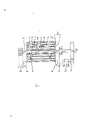
Fig. 2 is a permanent magnetic pulley ring type separator structural representation
(1)-Nei ring magnetic cylinder among Fig. 1, (2)-and the outer shroud magnetic cylinder, (3)-toroidal magnetic field passage, (4)-permanent magnet, be by NdFeB material, Ferrite Material, aluminium nickel cobalt material, samarium-cobalt material, samarium iron nitrogen material are manufactured (5)-magnetic conductor, be to make by pure iron, carbon steel material, (6)-and non-magnet material, be to make by magnetism-free stainless steel, copper, copper select, aluminium, aluminium alloy, plastics, nylon material
The utility model is achieved in that with any alternate being combined into of piece of permanent magnet (4) and magnetic conductor (5) and encircles magnetic cylinder (1) and outer shroud magnetic cylinder (2) in one that permanent magnet (4) on same ring magnetic cylinder and magnetic conductor (5) logarithm equate.The polarity of permanent magnet (4) as shown in Figure 1, adjacent two permanent magnets (4) produce new magnetic pole again in magnetic conductor (5), pole orientation as shown in Figure 1.Magnetic pole space (its space distance arbitrarily) between interior ring magnetic cylinder (1) and outer shroud magnetic cylinder (2) produces toroidal magnetic field passage (3).Two annular magnetic cylinders can pass through bolt, pin or be weldingly fixed on together, under the effect of driver (12), make the rotation of inner and outer rings magnetic cylinder one, allow material to be separated flow through toroidal magnetic field passage (3) (material to be separated can be solid, liquid) and be issued to magnetic and nonmagnetic substance separating substances in magnetic force, action of centrifugal force.For the permanent magnet in the protective device (4) with prolong its service life, and be convenient to collect the material of separating categorizedly and make structure, the utility model is described in detail below in conjunction with accompanying drawing 1,2,3 and embodiment as Fig. 2:
Manufacture a fume from steel making washes magnetic separating device by Fig. 1,2.Do magnet (4) with 16 pieces watts of shape Nd-Fe-Bo permanent magnet materials and do the interior ring magnetic cylinder (1) that magnetic conductor (5) is combined into the outer 400 * long 300 * thick 30mm of φ at interval with 16 blocks of pure iron, be combined in the φ isolating cylinder (6) that the skeleton magnetism-free stainless steel of φ a 340 * 5mm of cover is done in the ring magnetic cylinder (1) in the outer shroud magnetic cylinder (2) of 460 * long 300 * thick 30mm at interval with 16 neodymium iron borons and pure iron, and pass the axle (10) that No. 45 carbon steels are φ 44 * 700mm within it, it and outer shroud magnetic cylinder are fixed with pin, interior ring magnetic cylinder (1) is nested again with the outer shroud magnetic cylinder and uses bolt, pin, be weldingly fixed on together, the middle toroidal magnetic field passage (3) that forms, in interior ring magnetic cylinder (1) outside and outer shroud magnetic cylinder (2), fix a separation layer (7), it is that the thick corrosion resistant plate of 1.5mm is manufactured, one spirality scraper plate (9) is housed in toroidal magnetic field passage (3), at a toroidal magnetic field passage (a 3) mouthful feed hopper of top loose fit (14), at toroidal magnetic field passage (a 3) mouthful magnetic metal discharging opening of bottom, two ends loose fit (16) and nonmagnetic substance discharging opening (15), outer ring magnetic cylinder (2) overcoat one φ 300 * 450 * thick 5mm magnetism-free stainless steel is done shell (8), axle (10) two is fixed in the bearing of retort stand (13), there are an elongation and change tooth speed roller box (11) to link, gearbox (11) joins with driver (12), and driver (12) is used commercially available motor.
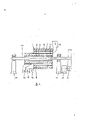
Embodiment 2: Fig. 3 is a kind of structural representation of permanent magnetic pulley ring type separator
Manufacture the separator of a sorting junk by Fig. 1,3.Do permanent magnet (4) with 8 pieces watts of shape aluminium nickel cobalts and do the interior ring magnetic cylinder (1) that magnetic conductor (5) is combined into outer 400 * 700 * thick 70mm of φ at interval with 8 blocks of No. 10 carbon steels, other pieces together the outer shroud magnetic cylinder (2) of 500 * 500 * thick 70mm in the φ, φ 650 * 500 * thick 10mm shell that outside the outer shroud magnetic cylinder, has a usefulness stainless steel to do, tightly pack into an isolating cylinder (6) of being φ 260 * 500 * thick 80mm of non-magnetic conductive steel at interior ring magnetic cylinder (1) inwall, outer shroud magnetic cylinder (2) is nested with interior ring magnetic cylinder (1), a sign indicating number of two is fixed them with bolt together, in the middle of two, form toroidal magnetic field passage (3), in its passage, fix the separation layer (7) that a bed thickness 2mm non-magnetic conductive steel is done, on the passway, locate a feed hopper of loose fit (14), passway Xia Chu has non-magnetic discharge bucket (15) and magnetic material discharging opening (16), ring magnetic cylinder (1) in the axle (10) that the 45# carbon steel of the outer 100 * 950mm of φ is done passes, and be fixed in the bearing on the retort stand (13), axle (10) one joins with speed-changing gear box, makes driver (12) and gearbox (11) joins with commercially available motor.The outer magnetic ring tube of this structure produces internal magnetic field, interior ring magnetic cylinder produces external magnetic field, inner and outer magnetic field constitutes the closed annular magnetic circuit, its magnetic loss is few, when whole magnetic cylinder is subjected to the whole rotation of extraneous driving force, when separated object was flowed through the toroidal magnetic field, separated object magnetic material under magnetic force, centrifugal force and stirring action was effectively separated with non-magnetic material.Be easy to generate high-intensity magnetic field, general magnetic field intensity is up to 6,000-10,000 oersteds.Use the utility model treating capacity can be any, and it is simple, convenient to make this device, and comparison produces so same equipment saving magnet steel of high-intensity magnetic field.
Claims (5)
1, a kind of by permanent magnet, magnetic conductor, cylinder, feed hopper, discharge bucket, shell, the permanent magnetic pulley ring type separator that motor is formed, it is characterized in that: by arbitrarily permanent magnet (4) and magnetic conductor (5) being combined into interior ring magnetic cylinder (1) and outer shroud magnetic cylinder (2) at interval, in the middle of being nested, two magnetic cylinders leave the space, and be fixed on one, space looping magnetic field passage (3) between two magnetic cylinders, at the fixing separation layer of one deck non-magnet material (7) of toroidal magnetic field passage (3) inwall, scraper plate (9) is housed within it, at its passage (3) mouthful feed hopper of top loose fit (14), one magnetic material discharge bucket (16) is arranged at the bottom, passway, non magnetic discharge bucket (15), the shell (8) that outside outer shroud magnetic cylinder (2), has a usefulness non-magnet material to do, driver (12) is direct, connect magnetic cylinder indirectly.
2, by the described permanent magnetic pulley ring type of claim 1 separator, it is characterized in that: it is that driver (12) links with speed changer (11) that said driver (12) connects with magnetic cylinder indirectly, one of speed changer (11) and axle (10) links, axle (10) passes in interior ring magnetic cylinder (1), and fix, in the bearing that is fixed on the support (13), the other end links with speed changer (11) by the bearing of support (13) again.
3, by the described permanent magnetic pulley ring type of claim 1 separator, it is characterized in that: said permanent magnet (4) is by NdFeB material, and Ferrite Material, aluminium nickel cobalt material, samarium-cobalt material, samarium iron nitrogen material are manufactured,
4, by the described permanent magnetic pulley ring type of claim 1 separator, it is characterized in that: said magnetic conductor (5) is to be manufactured by pure iron, carbon steel material,
5, by the described permanent magnetic pulley ring type of claim 1 separator, it is characterized in that: said non-magnet material (4) and separation layer (7) are to be made by magnetism-free stainless steel, copper, copper alloy, aluminium, aluminium alloy, plastics, nylon.
Priority Applications (1)
| Application Number | Priority Date | Filing Date | Title |
|---|---|---|---|
| CN 91218512 CN2117210U (en) | 1991-07-24 | 1991-07-24 | Permanent magnet rotary drum cycling seperating machine |
Applications Claiming Priority (1)
| Application Number | Priority Date | Filing Date | Title |
|---|---|---|---|
| CN 91218512 CN2117210U (en) | 1991-07-24 | 1991-07-24 | Permanent magnet rotary drum cycling seperating machine |
Publications (1)
| Publication Number | Publication Date |
|---|---|
| CN2117210U true CN2117210U (en) | 1992-09-30 |
Family
ID=4925973
Family Applications (1)
| Application Number | Title | Priority Date | Filing Date |
|---|---|---|---|
| CN 91218512 Granted CN2117210U (en) | 1991-07-24 | 1991-07-24 | Permanent magnet rotary drum cycling seperating machine |
Country Status (1)
| Country | Link |
|---|---|
| CN (1) | CN2117210U (en) |
Cited By (5)
| Publication number | Priority date | Publication date | Assignee | Title |
|---|---|---|---|---|
| CN1917959B (en) * | 2004-02-17 | 2013-03-27 | 纳幕尔杜邦公司 | Magnetic field and field gradient enhanced centrifugation solid-liquid separations |
| CN103056027A (en) * | 2013-01-11 | 2013-04-24 | 武汉理工大学 | Substance separating sieve |
| CN106216091A (en) * | 2016-08-25 | 2016-12-14 | 广东工业大学 | A kind of device and method separating and recovering magnetic nanoparticle |
| CN111983537A (en) * | 2020-08-19 | 2020-11-24 | 深圳航天科技创新研究院 | A Magnetic Resonance Magnet Structure Separating Magnetic Conductivity and Load-bearing Functions |
| CN115376777A (en) * | 2022-07-26 | 2022-11-22 | 包头稀土研究院 | High-field-intensity permanent magnetic circuit for room-temperature magnetic refrigeration and use method thereof |
-
1991
- 1991-07-24 CN CN 91218512 patent/CN2117210U/en active Granted
Cited By (8)
| Publication number | Priority date | Publication date | Assignee | Title |
|---|---|---|---|---|
| CN1917959B (en) * | 2004-02-17 | 2013-03-27 | 纳幕尔杜邦公司 | Magnetic field and field gradient enhanced centrifugation solid-liquid separations |
| CN103056027A (en) * | 2013-01-11 | 2013-04-24 | 武汉理工大学 | Substance separating sieve |
| CN103056027B (en) * | 2013-01-11 | 2015-08-12 | 武汉理工大学 | Sub-prime is sieved |
| CN106216091A (en) * | 2016-08-25 | 2016-12-14 | 广东工业大学 | A kind of device and method separating and recovering magnetic nanoparticle |
| CN106216091B (en) * | 2016-08-25 | 2018-05-18 | 广东工业大学 | A kind of device and method for separating and recovering magnetic nanoparticle |
| CN111983537A (en) * | 2020-08-19 | 2020-11-24 | 深圳航天科技创新研究院 | A Magnetic Resonance Magnet Structure Separating Magnetic Conductivity and Load-bearing Functions |
| CN111983537B (en) * | 2020-08-19 | 2023-06-06 | 深圳航天科技创新研究院 | Magnetic resonance magnet structure with separated magnetic conduction and bearing functions |
| CN115376777A (en) * | 2022-07-26 | 2022-11-22 | 包头稀土研究院 | High-field-intensity permanent magnetic circuit for room-temperature magnetic refrigeration and use method thereof |
Similar Documents
| Publication | Publication Date | Title |
|---|---|---|
| CN101474593B (en) | Permanent magnet high-field intensity magnetic filter | |
| CN101402069A (en) | Split type multi-roller multi-component high-gradient vibration magnetic separator in permanent magnetism | |
| CN110331294A (en) | A kind of automation equipment for the dissolution of neodymium iron boron waste material rare earth element | |
| CN101703964B (en) | Superconducting magnetic separator | |
| CN2117210U (en) | Permanent magnet rotary drum cycling seperating machine | |
| CN102179297B (en) | Permanent-magnet cylindrical cage type high-gradient magnetic separator with high processing capacity | |
| CN211937379U (en) | A composite magnetic system for a flat ring high gradient magnetic separator | |
| CN2289609Y (en) | Permanent magnetic roller dry magnetic separator | |
| CN202290290U (en) | Permanent magnet vertical ring high-gradient strong magnetic separator | |
| CN2262460Y (en) | Separator | |
| CN220697084U (en) | Embedded electromagnetic multi-vertical-ring high-gradient magnetic separator | |
| CN2308441Y (en) | Rare-earth permanent-magnet strong magnetic field dry magnetic separator | |
| CN201357111Y (en) | Permanent-magnet high field-intensity magnetic filter | |
| CN219424602U (en) | Halbach arrangement type magnetic separation roller | |
| CN2404130Y (en) | Magnet apparatus using for magnetic resonance imaging system | |
| CN218308494U (en) | Vertical ring pulsating superconducting magnetic separator | |
| CN2925614Y (en) | Permanent-magnet sorting apparatus for height-adjusting vertical-circular pulsed gradient magnetic field | |
| CN116984119A (en) | A flat-ring dry magnetic separation device and method for iron ore | |
| CN2449808Y (en) | Rare earth permanent-magnet high-gradient strong magnetic dry magnetic separator | |
| CN1021726C (en) | Multielement quotient gradient permanent strong magnetic separator | |
| CN201067706Y (en) | Non-ferrous metals permanent magnetic whirling current separator | |
| CN101823020A (en) | Permanent magnet vibration module type magnetic separator | |
| CN201098643Y (en) | Chain ring type magnetic separator | |
| CN223265305U (en) | A multi-gradient magnetic mud adsorption device | |
| JP3955927B2 (en) | Eddy current type nonferrous metal separator |
Legal Events
| Date | Code | Title | Description |
|---|---|---|---|
| C06 | Publication | ||
| PB01 | Publication | ||
| C14 | Grant of patent or utility model | ||
| GR01 | Patent grant | ||
| C19 | Lapse of patent right due to non-payment of the annual fee | ||
| CF01 | Termination of patent right due to non-payment of annual fee |