CN211592762U - Rhombus chassis structure - Google Patents
Rhombus chassis structure Download PDFInfo
- Publication number
- CN211592762U CN211592762U CN201921209587.1U CN201921209587U CN211592762U CN 211592762 U CN211592762 U CN 211592762U CN 201921209587 U CN201921209587 U CN 201921209587U CN 211592762 U CN211592762 U CN 211592762U
- Authority
- CN
- China
- Prior art keywords
- wheel
- rhombus
- automobile
- auxiliary
- chassis structure
- Prior art date
- Legal status (The legal status is an assumption and is not a legal conclusion. Google has not performed a legal analysis and makes no representation as to the accuracy of the status listed.)
- Active
Links
- 229910003460 diamond Inorganic materials 0.000 claims description 5
- 239000010432 diamond Substances 0.000 claims description 5
- 238000005265 energy consumption Methods 0.000 abstract description 10
- 230000001360 synchronised effect Effects 0.000 abstract description 2
- 238000005096 rolling process Methods 0.000 description 8
- QNRATNLHPGXHMA-XZHTYLCXSA-N (r)-(6-ethoxyquinolin-4-yl)-[(2s,4s,5r)-5-ethyl-1-azabicyclo[2.2.2]octan-2-yl]methanol;hydrochloride Chemical compound Cl.C([C@H]([C@H](C1)CC)C2)CN1[C@@H]2[C@H](O)C1=CC=NC2=CC=C(OCC)C=C21 QNRATNLHPGXHMA-XZHTYLCXSA-N 0.000 description 3
- 230000002035 prolonged effect Effects 0.000 description 3
- 238000000034 method Methods 0.000 description 2
- 230000002146 bilateral effect Effects 0.000 description 1
- 230000006872 improvement Effects 0.000 description 1
- 230000007246 mechanism Effects 0.000 description 1
- 230000004048 modification Effects 0.000 description 1
- 238000012986 modification Methods 0.000 description 1
- 230000008569 process Effects 0.000 description 1
Images


Landscapes
- Vehicle Body Suspensions (AREA)
Abstract
The utility model provides a rhombus chassis structure, including front wheel, rear wheel, left wheel and right wheel, front wheel, rear wheel, left wheel and right wheel are the rhombus and arrange, front wheel and rear wheel are the directive wheel and turn to in step, left wheel and right wheel are fixed. The utility model discloses a rhombus chassis structure arranges through the rhombus of four-wheel, and the front and back wheel synchronous steering, and the fixed roll of auxiliary wheel does not turn to, realizes that the four-wheel is same center motion that turns to, and is more stable and nimble when turning to, can also reduce the friction that tire and ground produced, reduces the energy consumption, improves the electric quantity availability factor of car, can also improve the life of tire simultaneously.
Description
Technical Field
The utility model relates to a vehicle engineering's technical field, in particular to rhombus chassis structure.
Background
The development of automobiles, especially cars, has undergone the processes of simple to complex structure, increasingly perfect performance and higher safety and comfort, but until now, the automobiles are classified into three-wheeled automobiles and four-wheeled automobiles according to the layout of wheels, wherein the front axle of the three-wheeled automobiles is provided with a single wheel, the rear axle of the three-wheeled automobiles is provided with a left wheel and a right wheel, and the front axle and the rear axle of the four-wheeled automobiles are provided with a left wheel and a right wheel. Automobiles of this conventional layout have been developed over the years and improved to continue to improve safety and stability with little margin. In order to improve the safety and stability of automobiles, a diamond-shaped automobile has been developed.
The energy consumption of the rhombic automobile is mainly reflected in factors such as an engine, the total mass of the automobile, the appearance of the automobile, tires of the automobile and the like, the influence of the tires of the automobile on rolling friction and sliding friction is great, if the rolling friction and/or the sliding friction of the tires can be reduced, the energy consumption of the automobile can be reduced, the automobile is more stable and flexible in steering, the front wheels and the rear wheels of the existing rhombic automobile are driven wheels, the left wheels and the right wheels are driving wheels, the front wheels and the right wheels are in contact with the ground in driving, the rolling friction and the sliding friction are large in numerical value, the energy consumption is high, the stability and the flexibility are not enough in steering, the service life of the tires is not.
SUMMERY OF THE UTILITY MODEL
An object of the utility model is to overcome above-mentioned prior art not enough, provide a rhombus chassis structure, mainly reduce the friction that tire and ground produced, reduce the energy consumption, improve the life of tire.
In order to realize the purpose, the utility model provides a rhombus chassis structure, including front wheel, rear wheel, left wheel and right wheel, front wheel, rear wheel, left wheel and right wheel are the rhombus and arrange, front wheel and rear wheel are for turning to the wheel and turn to in step, left wheel and right wheel are fixed, arrange through the rhombus of four-wheel, and the front and rear wheel turns to in step, and the fixed roll of left and right sides wheel does not turn to, realizes that the four-wheel is same turn to central motion, and is more stable and nimble when turning to.
Preferably, the front wheel or/and the rear wheel is a driving wheel, the left wheel and the right wheel are auxiliary wheels, and the bottom surfaces of the auxiliary wheels are slightly higher than the ground. The auxiliary wheel of the automobile is arranged to be off the ground when the automobile runs linearly and to be grounded when the automobile turns, so that the contact with the ground is reduced, only rolling friction is generated when the automobile turns, sliding friction is not generated, the energy consumption of the automobile is reduced, and the service life of the tire is prolonged.
Preferably, the angle between the front wheel and the connecting line between the left wheel and the right wheel is 60 degrees. The front wheels are always arranged to turn in a fan shape with the left or right wheels as the center, so that the side turning of the automobile can be prevented, and the safety is high during the side collision of the automobile.
Preferably, the width of the auxiliary wheel is smaller than the width of the driving wheel. The automobile steering is more flexible, the rolling friction with the ground is reduced, and the oil consumption is less.
Preferably, the width of the auxiliary wheel is one third of the width of the driving wheel.
The utility model has the advantages that:
1. through the rhombic arrangement of the four wheels, the front wheel and the rear wheel synchronously steer, and the auxiliary wheel fixedly rolls without steering, so that the four wheels do the same steering center motion, and the steering is more stable and flexible;
2. the front wheels or the rear wheels or the front wheels and the rear wheels are driven, the left auxiliary wheels and the right auxiliary wheels are driven to lift off the ground when driving in a straight line, and the left auxiliary wheels and the right auxiliary wheels are grounded when steering, so that the contact with the ground is reduced, only rolling friction is generated when steering, sliding friction is not generated, the energy consumption of an automobile is reduced, and the service life of tires is prolonged;
3. the included angle between the front wheel and the connecting line between the left wheel and the right wheel is 60 degrees, so that the side turning of the automobile is prevented, and the safety is high during the side collision of the automobile;
4. the width of the auxiliary wheel is set to be smaller than that of the driving wheel, so that the automobile steering is more flexible, the rolling friction with the ground is reduced, and the energy consumption is lower;
5. under the same energy consumption, the driving range of the automobile is 2 times or more than that of the ordinary automobile.
Drawings
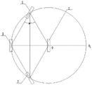
Fig. 1 is a schematic view of the overall structure of the embodiment of the present invention.
Fig. 2 is a first schematic view of the steering of the automobile.
Fig. 3 is a second schematic view of the steering of the automobile.
In the figure: 1-front wheel, 2-rear wheel, 3-left auxiliary wheel and 4-right auxiliary wheel.
Detailed Description
In order to make the objects, technical solutions and advantages of the present invention more clear, the present invention is further described in detail through the accompanying drawings and embodiments. It should be understood, however, that the description herein of specific embodiments is only intended to illustrate the invention and not to limit the scope of the invention. Moreover, in the following description, descriptions of well-known structures and techniques are omitted so as to not unnecessarily obscure the concepts of the present invention.
As shown in fig. 1 to 3, the utility model relates to a rhombus chassis structure, including front wheel 1, rear wheel 2, left wheel 3 and right wheel 4, front wheel 1, rear wheel 2, left wheel 3 and right wheel 4 are the rhombus and arrange, and front wheel 1 and rear wheel 2 are on same straight line, are the directive wheel and turn to in step, and left wheel 3 and right wheel 4 are located the perpendicular bisector of front wheel 1 and rear wheel 2 and bilateral symmetry distributes, left wheel 3 and right wheel 4 are fixed to roll, realize that the same center of turning to motion is done to the four-wheel, and are more stable and nimble during turning to, front wheel 1 is 60 with the line contained angle between left wheel 3 and the right wheel 4 respectively, front wheel 1 and rear wheel 2 are the drive wheel, left wheel 3 and right wheel 4 are the auxiliary wheel, the drive wheel is on the circular arc with the auxiliary wheel as the center all the time, and the radius of circle is the distance between the center of left wheel 3 and the center of right wheel 4, and front wheel 1, The rear wheel 2, the left wheel 3 and the right wheel 4 form a 60-degree diamond structure,
as shown in fig. 1, a central point of a front wheel 1 is a, a central point of a left wheel 3 is B, a central point of a rear wheel 2 is C, a central point of a right wheel 4 is D, four wheels are distributed in a 60-degree diamond shape, AB = BC = CD = DA = BD, and angle BAD =60 °, a front wheel 11 and a rear wheel 22 are steering wheels, longitudinal planes of the wheels are overlapped, the front wheel 1 and the rear wheel 2 are linked through a steering mechanism, synchronous steering of the front wheel 1 and the rear wheel 2 is realized, angles are equal, directions are opposite, turning radii are small, and operation is more flexible.
More specifically, the bottom surface of the auxiliary wheel is slightly higher than the ground, so that the auxiliary wheel is lifted off the ground when the automobile runs straight, and is grounded when the automobile turns, the contact with the ground is reduced, only rolling friction is generated when the automobile turns, sliding friction is not generated, the energy consumption of the automobile is reduced, and the service life of the tire is prolonged.
More specifically, the width of auxiliary wheel is less than the width of drive wheel, specifically is one third of the width of front wheel 1 or rear wheel 2, and the car turns to more nimble, and the friction with the ground reduces, and the oil consumption is littleer.
The above description is only exemplary of the present invention and should not be taken as limiting the scope of the present invention, as any modification, equivalent replacement or improvement made within the spirit and principle of the present invention should be included in the present invention.
Claims (4)
1. A rhombus chassis structure which characterized in that: including front wheel, rear wheel, left wheel and right wheel, front wheel, rear wheel, left wheel and right wheel are the rhombus and arrange, front wheel and rear wheel are the directive wheel and turn to in step, left wheel and right wheel are fixed, front wheel or/and rear wheel are the drive wheel, left wheel and right wheel are the auxiliary wheel, and the wheel bottom surface of auxiliary wheel is a little higher than ground.
2. The diamond shaped chassis structure of claim 1, wherein: the front wheel respectively forms an included angle of 60 degrees with a connecting line between the left wheel and the right wheel.
3. The diamond shaped chassis structure of claim 1, wherein: the width of the auxiliary wheel is smaller than that of the driving wheel.
4. The diamond shaped chassis structure of claim 3, wherein: the width of the auxiliary wheel is one third of the width of the driving wheel.
Priority Applications (1)
| Application Number | Priority Date | Filing Date | Title |
|---|---|---|---|
| CN201921209587.1U CN211592762U (en) | 2019-07-30 | 2019-07-30 | Rhombus chassis structure |
Applications Claiming Priority (1)
| Application Number | Priority Date | Filing Date | Title |
|---|---|---|---|
| CN201921209587.1U CN211592762U (en) | 2019-07-30 | 2019-07-30 | Rhombus chassis structure |
Publications (1)
| Publication Number | Publication Date |
|---|---|
| CN211592762U true CN211592762U (en) | 2020-09-29 |
Family
ID=72574936
Family Applications (1)
| Application Number | Title | Priority Date | Filing Date |
|---|---|---|---|
| CN201921209587.1U Active CN211592762U (en) | 2019-07-30 | 2019-07-30 | Rhombus chassis structure |
Country Status (1)
| Country | Link |
|---|---|
| CN (1) | CN211592762U (en) |
Cited By (1)
| Publication number | Priority date | Publication date | Assignee | Title |
|---|---|---|---|---|
| CN116771129A (en) * | 2023-06-21 | 2023-09-19 | 上海公路桥梁(集团)有限公司 | Wheel leg type steel bar bundling robot moving chassis |
-
2019
- 2019-07-30 CN CN201921209587.1U patent/CN211592762U/en active Active
Cited By (1)
| Publication number | Priority date | Publication date | Assignee | Title |
|---|---|---|---|---|
| CN116771129A (en) * | 2023-06-21 | 2023-09-19 | 上海公路桥梁(集团)有限公司 | Wheel leg type steel bar bundling robot moving chassis |
Similar Documents
| Publication | Publication Date | Title |
|---|---|---|
| CN112092552B (en) | Unmanned vehicle chassis structure with telescopic rocker suspension | |
| US20070151777A1 (en) | Wheel Arrangement For A Four-Wheeled Vehicle | |
| CN106956585A (en) | A kind of band turning function two-stage planetary reduction wheel hub direct driving device | |
| CN104890529A (en) | Electric car | |
| CN211592762U (en) | Rhombus chassis structure | |
| EP2589502B1 (en) | Pneumatic tire | |
| TWM590560U (en) | Electric vehicle | |
| CN203063554U (en) | Hub | |
| CN112455206A (en) | Electric patrol car driven by front-mounted motor | |
| CN218929637U (en) | Electric vehicle | |
| CN203402252U (en) | Special pure electric drive chassis platform of truss-type structure | |
| CN201646907U (en) | Rhombus shaped automobile | |
| CN210851916U (en) | Automobile driving assembly and automobile chassis comprising same | |
| CN202358170U (en) | Four-wheel vehicle | |
| CN208558863U (en) | A kind of Noise reduction tire | |
| EP1905675B1 (en) | Wheel arrangement for a four-wheeled vehicle | |
| CN114454662A (en) | Automobile spherical wheel device capable of being used for transverse driving and increasing turning angle | |
| CN219312849U (en) | A kind of rear wheel follow-up steering of Baja racing car | |
| CN2331560Y (en) | Damping thrush bearing for knuckle of vehicle | |
| CN207028722U (en) | Tricycle pneumatic tire | |
| CN219650950U (en) | Tire tread and SUV tire | |
| CN220639429U (en) | Double-fork arm independent suspension for reducing lateral sideslip of wheel | |
| CN109823164A (en) | Narrow body independent drive two-wheeler | |
| CN103507854A (en) | Double-trapezoid broken type steering mechanism | |
| CN219506084U (en) | Mechanical front-rear steering switching system of automobile |
Legal Events
| Date | Code | Title | Description |
|---|---|---|---|
| GR01 | Patent grant | ||
| GR01 | Patent grant |