CN211553199U - Leak detection tool for fuel cell stack sealing element - Google Patents
Leak detection tool for fuel cell stack sealing element Download PDFInfo
- Publication number
- CN211553199U CN211553199U CN201922474544.2U CN201922474544U CN211553199U CN 211553199 U CN211553199 U CN 211553199U CN 201922474544 U CN201922474544 U CN 201922474544U CN 211553199 U CN211553199 U CN 211553199U
- Authority
- CN
- China
- Prior art keywords
- bottom plate
- apron
- fuel cell
- seal groove
- sealing member
- Prior art date
- Legal status (The legal status is an assumption and is not a legal conclusion. Google has not performed a legal analysis and makes no representation as to the accuracy of the status listed.)
- Active
Links
- 238000007789 sealing Methods 0.000 title claims abstract description 59
- 239000000446 fuel Substances 0.000 title claims abstract description 24
- 238000001514 detection method Methods 0.000 title claims description 10
- 210000003437 trachea Anatomy 0.000 claims abstract description 15
- 238000007689 inspection Methods 0.000 abstract description 3
- 208000002925 dental caries Diseases 0.000 abstract description 2
- 239000012495 reaction gas Substances 0.000 description 5
- UFHFLCQGNIYNRP-UHFFFAOYSA-N Hydrogen Chemical compound [H][H] UFHFLCQGNIYNRP-UHFFFAOYSA-N 0.000 description 4
- 239000001257 hydrogen Substances 0.000 description 4
- 229910052739 hydrogen Inorganic materials 0.000 description 4
- 238000000034 method Methods 0.000 description 4
- XLYOFNOQVPJJNP-UHFFFAOYSA-N water Substances O XLYOFNOQVPJJNP-UHFFFAOYSA-N 0.000 description 3
- QVGXLLKOCUKJST-UHFFFAOYSA-N atomic oxygen Chemical compound [O] QVGXLLKOCUKJST-UHFFFAOYSA-N 0.000 description 2
- 230000000694 effects Effects 0.000 description 2
- 238000004880 explosion Methods 0.000 description 2
- 239000000463 material Substances 0.000 description 2
- 239000012528 membrane Substances 0.000 description 2
- 239000007800 oxidant agent Substances 0.000 description 2
- 230000001590 oxidative effect Effects 0.000 description 2
- 239000001301 oxygen Substances 0.000 description 2
- 229910052760 oxygen Inorganic materials 0.000 description 2
- 239000007787 solid Substances 0.000 description 2
- 238000007792 addition Methods 0.000 description 1
- 230000009286 beneficial effect Effects 0.000 description 1
- 230000000903 blocking effect Effects 0.000 description 1
- 239000003054 catalyst Substances 0.000 description 1
- 238000004891 communication Methods 0.000 description 1
- 230000007547 defect Effects 0.000 description 1
- 238000005516 engineering process Methods 0.000 description 1
- 239000007789 gas Substances 0.000 description 1
- 239000011521 glass Substances 0.000 description 1
- 238000005259 measurement Methods 0.000 description 1
- 238000012986 modification Methods 0.000 description 1
- 230000004048 modification Effects 0.000 description 1
- 239000000178 monomer Substances 0.000 description 1
- 230000000149 penetrating effect Effects 0.000 description 1
- 238000010248 power generation Methods 0.000 description 1
- 229910052710 silicon Inorganic materials 0.000 description 1
- 239000010703 silicon Substances 0.000 description 1
- 239000000126 substance Substances 0.000 description 1
- 239000000758 substrate Substances 0.000 description 1
- 238000012360 testing method Methods 0.000 description 1
- 239000012780 transparent material Substances 0.000 description 1
Images


Landscapes
- Fuel Cell (AREA)
Abstract
The utility model relates to a leak hunting frock of fuel cell galvanic pile sealing member, including bottom plate (1), sealing member (2) and apron (3), the internal surface of bottom plate (1) and apron (3) is equipped with bottom plate seal groove (4) and apron seal groove (5) of mutually supporting, bottom plate seal groove (4) and apron seal groove (5) are located in sealing member (2), be equipped with a plurality of trachea joints on the surface of apron (3), the internal surface of apron (3) be equipped with the trachea export that the trachea joint corresponds, the trachea export corresponds the seal chamber who forms after with sealing member (2) pressfitting by bottom plate seal groove (4), apron seal groove (5) respectively. Compared with the prior art, the utility model has the advantages of have outer hourglass inspection concurrently and leak the inspection in with, be applicable to the sealing member that possess a plurality of cavitys.
Description
Technical Field
The utility model belongs to the technical field of fuel cell and specifically relates to a leak hunting frock of fuel cell pile sealing member is related to.
Background
The fuel cell is a power generation cell which directly converts chemical energy stored in hydrogen fuel and oxygen (air) into electric energy, and the fuel cell monomer consists of a membrane electrode, a bipolar plate, a sealing element and a structural connecting piece. The membrane electrode is used for the reaction of hydrogen fuel and oxidant; the bipolar plate has the functions of uniformly distributing reaction gas, collecting current, leading out electric energy, blocking the reaction gas and the like. The sealing element has sealing effect and prevents the reaction gas from penetrating and leaking. If the sealing effect of the sealing element is poor and the phenomenon of mutual gas communication in the reaction gas occurs, the hydrogen and the oxygen react directly under the action of the catalyst to generate a large amount of heat rapidly, so that the battery is seriously damaged, and the hydrogen fuel and the oxidant can also cause explosion when mixed to a certain concentration. If reaction gas leaks to the outside of the battery, on one hand, the fuel utilization rate can be reduced, the performance of the battery is reduced, and on the other hand, if the space around the outside of the battery is limited, extremely dangerous explosion can also occur when the leakage exceeds a certain concentration, and even the personal safety is damaged. Therefore, battery sealing is a very important technology. The performance of the seal has a critical impact on the electrochemical function of the stack and its life, and the seal material and resulting seal must pass a strict measurement of the sealing performance before the seal can be used in the stack.
Chinese patent CN204028330U discloses a method for detecting the sealing performance of a sealing element of a solid oxide fuel cell, wherein the sealing element is positioned and placed by a positioning substrate and a cover plate, a thermoelectric furnace simulates the running state of a solid oxide fuel cell stack, a flowmeter is used for testing the leakage condition of the sealing element, a curve is drawn according to the detection data, and the slope is used for representing the sealing performance of the sealing element. However, the sealing element material detected by the patent does not include soft silicon, and the leakage position of the sealing element cannot be observed in the tool clamp.
The problem of detecting the sealing performance of a common circular sealing ring in Chinese patent CN208953218U is solved, but the circular cross-section structure can only detect single-cavity sealing, and the structure is simpler.
SUMMERY OF THE UTILITY MODEL
The utility model aims at providing a leak hunting frock of fuel cell galvanic pile sealing member in order to overcome the leakproofness that above-mentioned prior art exists can only detect single cavity, can't observe the defect of revealing the position.
The purpose of the utility model can be realized through the following technical scheme:
the utility model provides a leak hunting frock of fuel cell galvanic pile sealing member, includes bottom plate, sealing member and apron, the internal surface of bottom plate and apron is equipped with bottom plate seal groove and the apron seal groove of mutually supporting, the sealing member is located in bottom plate seal groove and the apron seal groove, be equipped with a plurality of trachea connectors on the surface of apron, the internal surface of apron be equipped with the trachea export that the trachea connector corresponds, the trachea export corresponds the seal chamber who forms after the same sealing member pressfitting by bottom plate seal groove, apron seal groove respectively.
The bottom plate and the cover plate are of a square structure.
The cover plate is provided with a plurality of cover plate threaded holes along the edge.
The base plate threaded holes are respectively arranged at the trisection points of the two long edges of the base plate, and the cover plate threaded holes are respectively arranged at the trisection points of the two long edges of the cover plate.
Preferably, the bottom plate is provided with a guide post.
The number of the guide posts is 2, and the guide posts are arranged on two vertexes of the bottom plate at diagonal positions.
And the cover plate is provided with a guide post groove corresponding to the guide post.
The number of the air pipe joints is 7, and each air pipe joint is communicated with an air pipe outlet which is arranged right below the fixed point on the cover plate.
Compared with the prior art, the utility model discloses following beneficial effect has:
1. the utility model discloses a corresponding every seal chamber and setting up the trachea and connect, realize every seal chamber's independent control, conveniently detect the leakproofness between a plurality of seal chambers, be applicable to the sealing member that possess a plurality of cavitys.
2. The utility model discloses a be equipped with the guide pillar on the bottom plate, through cooperating with the guide pillar groove on the apron, make things convenient for operating personnel to fix the relative position of bottom plate and apron in advance before the bolt of tightening bottom plate and apron, improve the stability of bottom plate and cover connection process.
3. The utility model discloses a position of the appearance of bubble can accurately judge the leakage point of sealing member, examines the interior hourglass of sealing member, if put the device in aqueous, observe the position of bubble then the outer hourglass of detectable sealing member, promoted the inspection coverage of leakage point.
Drawings
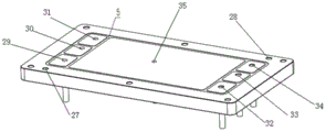
Fig. 1 is a schematic structural view of the present invention;
fig. 2 is a schematic structural view of the outer surface of the cover plate of the present invention;
fig. 3 is a schematic structural view of the inner surface of the cover plate of the present invention;
fig. 4 is a schematic structural view of the inner surface of the bottom plate of the present invention.
Reference numerals:
1-a bottom plate; 2-a seal; 3-cover plate; 4-bottom plate seal groove; 5-cover plate sealing groove; 6-7-guide posts; 8-13-threaded holes of the bottom plate; 14-19-cover plate threaded holes; 20-26-air pipe joint; 27-28-guide post groove; 29-35-outlet of air pipe.
Detailed Description
The present invention will be described in detail below with reference to the accompanying drawings and specific embodiments. The embodiment is implemented on the premise of the technical solution of the present invention, and a detailed implementation manner and a specific operation process are given, but the scope of the present invention is not limited to the following embodiments.
As shown in figure 1, a leak hunting frock of fuel cell galvanic pile sealing member, including bottom plate 1, sealing member 2 and apron 3, bottom plate 1 and apron 3 are transparent material, including but not limited to transparent ya keli and glass, the internal surface of bottom plate 1 and apron 3 is equipped with bottom plate seal groove 4 and apron seal groove 5 of mutually supporting, sealing member 2 is located in bottom plate seal groove 4 and apron seal groove 5, as shown in figure 2, be equipped with a plurality of pipe connections 20 ~ 26 on the surface of apron 3, the internal surface of apron 3 is equipped with the trachea export 29 ~ 35 that corresponds with the pipe connection, trachea export 29 ~ 35 correspond respectively by bottom plate seal groove 4, the sealed cavity that forms after apron seal groove 5 and the pressfitting of sealing member 2.
The bottom plate 1 and the cover plate 3 are of a square structure.
The edge of the bottom plate 1 is provided with a plurality of bottom plate threaded holes 8-13, and the edge of the cover plate 3 is provided with a plurality of cover plate threaded holes 14-19.
As shown in fig. 4, the bottom plate screw holes 8 to 13 are respectively provided at trisections of two long sides of the bottom plate 1, and the cover plate screw holes 14 to 19 are respectively provided at trisections of two long sides of the cover plate 3.
The bottom plate 1 is provided with guide posts 6-7, which are arranged on two vertexes of the bottom plate 1 at diagonal positions, and as shown in fig. 3, the cover plate 3 is provided with guide post grooves 27-28 corresponding to the guide posts 6-7.
Each air pipe joint is communicated with an air pipe outlet which is arranged right below the fixed point of the air pipe joint on the cover plate 3.
Example one
The sealing element 2 is placed in a bottom plate sealing groove 4 of the bottom plate 1, the cover plate 3 is aligned with the guide pillars 6-7 through the guide pillar grooves 27-28, the relative positions of the bottom plate 1 and the cover plate 3 are determined, screws are placed into threaded holes 14-19 of the upper cover plate to be fastened, and the bottom plate 1 and the cover plate 3 are tightly matched to form a sealing cavity. The air pipe connectors 20-26 are connected with an external air source, the external air source is connected with a precision flowmeter, the connected tool is integrally placed into water, air pressure is adjusted to inflate each seal cavity, leakage points can be observed through the positions where air bubbles appear, and leakage amount can be seen through the precision flowmeter. If the internal leakage needs to be checked, the air pipe joint of one cavity is communicated with an external air source to inflate the internal air, the air pipe joint of the adjacent sealed cavity is communicated with an external water source to fill water into the sealed cavity, and the internal leakage point of the sealing piece can be observed through the position where the bubbles appear.
Example two
The sealing element 2 is placed in a bottom sealing groove 4 of the bottom plate 1, the bipolar plate is placed on the sealing element 2, the sealing element 2 is placed in a cover plate sealing groove 5 which is designed in an aligning mode on the cover plate 3, a sealing cavity is formed by closely aligning and matching guide pillars 6-7, meanwhile, a stop piece for controlling the distance is added, and screws are placed in threaded holes 14-19 of the upper cover plate to be fastened. The rest of the operation steps are the same as the first embodiment.
In addition, it should be noted that the shapes of the components, the names of the components, and the like of the specific embodiments described in the present specification may be different, and the above description is only an example of the structure of the present invention. All minor or simple changes made according to the structure, characteristics and principles of the present invention are included in the protection scope of the present invention. Various modifications or additions may be made to the described embodiments or similar methods may be adopted by those skilled in the art without departing from the scope of the invention as defined in the claims.
Claims (8)
1. The utility model provides a leak hunting frock of fuel cell galvanic pile sealing member, includes bottom plate (1), sealing member (2) and apron (3), the internal surface of bottom plate (1) and apron (3) is equipped with bottom plate seal groove (4) and apron seal groove (5) of mutually supporting, in bottom plate seal groove (4) and apron seal groove (5) were located in sealing member (2), its characterized in that, be equipped with a plurality of trachea joints on the surface of apron (3), the internal surface of apron (3) be equipped with the trachea export that the trachea joint corresponds, the trachea export corresponds the seal chamber who forms after with sealing member (2) pressfitting by bottom plate seal groove (4), apron seal groove (5) respectively.
2. The leak detection tool for the fuel cell stack seal member according to claim 1, wherein the bottom plate (1) and the cover plate (3) are of a square structure.
3. The leak detection tool for the fuel cell stack sealing element according to claim 2, wherein the bottom plate (1) is provided with a plurality of bottom plate threaded holes along the edge, and the cover plate (3) is provided with a plurality of cover plate threaded holes along the edge.
4. The leak detection tool for the fuel cell stack sealing member according to claim 3, wherein the bottom plate threaded holes are respectively formed at trisections of two long sides of the bottom plate (1), and the cover plate threaded holes are respectively formed at trisections of two long sides of the cover plate (3).
5. The leak detection tool for the fuel cell stack sealing element according to claim 1, wherein a guide post is arranged on the bottom plate (1).
6. Leak detection tool for a fuel cell stack seal according to claim 5, characterized in that the number of said guide posts is 2, and said guide posts are provided on two opposite corners of said bottom plate (1).
7. The leak detection tool for the fuel cell stack sealing element according to claim 6, wherein a guide pillar groove corresponding to the guide pillar is formed in the cover plate (3).
8. The leak detection tool for the fuel cell stack sealing element according to claim 1, wherein the number of the gas pipe joints is 7, and each gas pipe joint is communicated with a gas pipe outlet which is right below a fixed point of the gas pipe joint on the cover plate (3).
Priority Applications (1)
| Application Number | Priority Date | Filing Date | Title |
|---|---|---|---|
| CN201922474544.2U CN211553199U (en) | 2019-12-31 | 2019-12-31 | Leak detection tool for fuel cell stack sealing element |
Applications Claiming Priority (1)
| Application Number | Priority Date | Filing Date | Title |
|---|---|---|---|
| CN201922474544.2U CN211553199U (en) | 2019-12-31 | 2019-12-31 | Leak detection tool for fuel cell stack sealing element |
Publications (1)
| Publication Number | Publication Date |
|---|---|
| CN211553199U true CN211553199U (en) | 2020-09-22 |
Family
ID=72512610
Family Applications (1)
| Application Number | Title | Priority Date | Filing Date |
|---|---|---|---|
| CN201922474544.2U Active CN211553199U (en) | 2019-12-31 | 2019-12-31 | Leak detection tool for fuel cell stack sealing element |
Country Status (1)
| Country | Link |
|---|---|
| CN (1) | CN211553199U (en) |
Cited By (1)
| Publication number | Priority date | Publication date | Assignee | Title |
|---|---|---|---|---|
| CN116973038A (en) * | 2023-09-25 | 2023-10-31 | 爱德曼氢能源装备有限公司 | Testing device for parts of fuel cell system |
-
2019
- 2019-12-31 CN CN201922474544.2U patent/CN211553199U/en active Active
Cited By (2)
| Publication number | Priority date | Publication date | Assignee | Title |
|---|---|---|---|---|
| CN116973038A (en) * | 2023-09-25 | 2023-10-31 | 爱德曼氢能源装备有限公司 | Testing device for parts of fuel cell system |
| CN116973038B (en) * | 2023-09-25 | 2024-01-02 | 爱德曼氢能源装备有限公司 | Testing device for parts of fuel cell system |
Similar Documents
| Publication | Publication Date | Title |
|---|---|---|
| CN201926543U (en) | Leakage detection device for membrane electrode of proton exchange membrane fuel cell | |
| CN109990952A (en) | A kind of fuel cell pile membrane electrode string leak detection system and method | |
| CN111540933A (en) | Fuel cell bipolar plate airtightness detection device and detection method | |
| CN108120568A (en) | A kind of fuel cell pile air-tightness care testing device | |
| CN103063375A (en) | An online test method for studying the assembly force and sealing performance of fuel cell stacks | |
| CN109253850A (en) | A kind of fuel battery double plates water cavity device for detecting sealability and its detection method | |
| CN100587465C (en) | A Simple Gas Permeability Tester | |
| CN111540932B (en) | Fuel cell leak detection device and leak detection method | |
| CN211553199U (en) | Leak detection tool for fuel cell stack sealing element | |
| CN115389125A (en) | Fuel cell bipolar plate airtightness detection device and detection method thereof | |
| CN201156005Y (en) | A fuel cell membrane electrode leak detection device | |
| CN111521348A (en) | A fuel cell leak detection end plate, leak detection device and leak detection method | |
| CN203178047U (en) | Rapid air tightness detection device for fuel cell stack | |
| CN217542298U (en) | Air tightness test equipment for fuel cell polar plate and membrane electrode | |
| CN110672275A (en) | Device and method for detecting welding leakage of bipolar plate, membrane electrode leakage and leakage outside galvanic pile | |
| CN101498613B (en) | Leakage detection apparatus for fuel cell membrane electrode | |
| CN212903770U (en) | Quick leak detection device for membrane electrode of fuel cell | |
| CN111446475B (en) | Device, system and method for detecting gas channeling point of membrane electrode of fuel cell | |
| CN212779790U (en) | Device for sealing and detecting bipolar plate | |
| CN212011146U (en) | Fuel cell membrane electrode gas blowby point detection device and detection system | |
| CN201867292U (en) | A fuel cell bipolar plate water cavity air tightness detection device | |
| CN211061131U (en) | Fuel cell electrolyte membrane gas tightness detection device and system | |
| CN109932132B (en) | A test leak detection device and application of a fuel cell membrane electrode | |
| CN219038300U (en) | Air tightness test device | |
| CN114414173B (en) | A fuel cell air tightness detection tool |
Legal Events
| Date | Code | Title | Description |
|---|---|---|---|
| GR01 | Patent grant | ||
| GR01 | Patent grant |