CN211112196U - A magnetic source structure of magnetron sputtering cathode - Google Patents
A magnetic source structure of magnetron sputtering cathode Download PDFInfo
- Publication number
- CN211112196U CN211112196U CN201922313233.8U CN201922313233U CN211112196U CN 211112196 U CN211112196 U CN 211112196U CN 201922313233 U CN201922313233 U CN 201922313233U CN 211112196 U CN211112196 U CN 211112196U
- Authority
- CN
- China
- Prior art keywords
- magnet
- magnets
- source structure
- magnetic
- magnetron sputtering
- Prior art date
- Legal status (The legal status is an assumption and is not a legal conclusion. Google has not performed a legal analysis and makes no representation as to the accuracy of the status listed.)
- Active
Links
Images


Landscapes
- Physical Vapour Deposition (AREA)
Abstract
本实用新型提供了一种磁控溅射阴极的磁源结构,所述磁源结构包括阴极靶和磁体组件,所述磁体组件设置于阴极靶下方;所述磁体组件包括横向磁体和纵向磁体,所述横向磁体和纵向磁体交替排列,相邻的纵向磁体的磁极相反,相邻的纵向磁体和横向磁体的磁极相同。本实用新型所述磁源结构通过在常规磁体的基础上增加横向磁体,并通过横向磁体和纵向磁体的排列方式,有效增强阴极靶表面附近的磁场强度;所述磁源结构中横向磁体位置的可调节性,可有效改变靶材表面磁场的分布情况,增强磁场分布的均匀性和一致性,使磁控溅射进行时靶材能够均匀消耗,提高镀膜质量。

The utility model provides a magnetic source structure of a magnetron sputtering cathode. The magnetic source structure includes a cathode target and a magnet assembly, the magnet assembly is arranged below the cathode target; the magnet assembly includes a transverse magnet and a longitudinal magnet, The transverse magnets and longitudinal magnets are alternately arranged, the magnetic poles of adjacent longitudinal magnets are opposite, and the magnetic poles of adjacent longitudinal magnets and transverse magnets are the same. The magnetic source structure of the present invention effectively enhances the magnetic field strength near the surface of the cathode target by adding transverse magnets on the basis of conventional magnets, and through the arrangement of transverse magnets and longitudinal magnets; Adjustability can effectively change the distribution of the magnetic field on the surface of the target, enhance the uniformity and consistency of the magnetic field distribution, so that the target can be uniformly consumed during magnetron sputtering, and the quality of the coating can be improved.
Description
技术领域technical field
本实用新型属于磁控溅射镀膜技术领域,涉及一种磁控溅射阴极的磁源结构。The utility model belongs to the technical field of magnetron sputtering coating, and relates to a magnetic source structure of a magnetron sputtering cathode.
背景技术Background technique
磁控溅射是物理气相沉积(PVD)法中的一种,一般的溅射法可被用于制备金属、半导体、绝缘体等多种材料,且具有设备简单、易于控制、镀膜面积大和附着力强等优点。上世纪70年代发展起来的磁控溅射法更是实现了高速、低温、低损伤。由于是在低气压条件下进行高速溅射,必须有效地提高气体的离化率,而磁控溅射通过在靶阴极表面引入磁场,利用磁场对带电粒子的约束来提高等离子体密度以增加溅射率。磁控溅射技术发展至今,在半导体、磁记录硬盘介质、射频MEMS、平板显示器等领域有广泛的应用。Magnetron sputtering is one of the physical vapor deposition (PVD) methods. The general sputtering method can be used to prepare various materials such as metals, semiconductors, insulators, etc., and has the advantages of simple equipment, easy control, large coating area and adhesion. strong and other advantages. The magnetron sputtering method developed in the 1970s has achieved high speed, low temperature and low damage. Since high-speed sputtering is carried out under low pressure conditions, the ionization rate of the gas must be effectively increased, while magnetron sputtering introduces a magnetic field on the surface of the target cathode and uses the magnetic field to confine charged particles to increase the plasma density to increase the sputtering. emissivity. Since the development of magnetron sputtering technology, it has been widely used in semiconductors, magnetic recording hard disk media, radio frequency MEMS, flat panel displays and other fields.
在现有的磁控溅射系统中,镀膜基片位于靶材的上方,靶材下方设有永磁体产生磁场,磁体下方则为极板,电子运动过程中与氩原子发生碰撞,使氩气电离产生Ar离子和电子,Ar离子飞向阴极靶,以高能量轰击靶材,使靶材发生溅射,在溅射过程中,中性的靶原子或分子沉积在基片形成薄膜。在此过程中,磁力线将电子约束在靶材表面附近,延长电子在等离子体中的运动轨迹,提高了电子与氩气分子碰撞和电离过程的几率,从而提高薄膜生长的效率。然而,目前所用的磁体多为条形磁体,条形磁体两端的表面磁通强度往往大于中间的表面磁通强度,磁场强度的分布不均匀性导致了阴极靶不同位置的刻蚀速度不均匀,降低了靶材的使用寿命,增加了工艺及原料成本。In the existing magnetron sputtering system, the coating substrate is located above the target, a permanent magnet is arranged below the target to generate a magnetic field, and a pole plate is below the magnet. Ionization produces Ar ions and electrons. Ar ions fly to the cathode target, bombard the target with high energy, and sputter the target. During the sputtering process, neutral target atoms or molecules are deposited on the substrate to form a thin film. During this process, the magnetic field lines confine the electrons near the surface of the target material, prolonging the trajectory of the electrons in the plasma, increasing the probability of the electrons colliding with argon gas molecules and ionizing the process, thereby improving the efficiency of thin film growth. However, most of the magnets currently used are bar magnets, and the surface magnetic flux intensity at both ends of the bar magnet is often larger than the surface magnetic flux intensity in the middle. The service life of the target is reduced, and the cost of the process and raw materials is increased.
CN 103046009A公开了一种平面磁控溅射阴极,其包括靶材、磁体装置、磁靴,所述磁体装置装设于靶材的背面,所述磁体装置包括平行且间隔设置的三个第一磁体,分别设置于靶材的两侧和中间,该磁体装置还包括四个第二磁体,两两一组设置于相邻的两个第一磁体之间,且该磁体装置中相邻的第一磁体与第二磁体的极性排布相反,相邻的两个第二磁体的极性排布相反。此种方式虽然能够在一定程度上使磁场强度分布更加均匀,但所有磁体仍是竖直设置,磁场强度分布的均匀性仍无法达到要求,且磁场分布无法发生变化。CN 103046009A discloses a planar magnetron sputtering cathode, which includes a target, a magnet device and a magnetic shoe, the magnet device is installed on the back of the target, and the magnet device includes three first parallel and spaced apart The magnets are respectively arranged on both sides and the middle of the target material, the magnet device further includes four second magnets, which are arranged in pairs between two adjacent first magnets, and the adjacent first magnets in the magnet device The polarity arrangement of one magnet is opposite to that of the second magnet, and the polarity arrangement of two adjacent second magnets is opposite. Although this method can make the magnetic field intensity distribution more uniform to a certain extent, all the magnets are still arranged vertically, the uniformity of the magnetic field intensity distribution still cannot meet the requirements, and the magnetic field distribution cannot be changed.
CN 107083537A公开了一种平面磁控溅射阴极,该平面磁控溅射阴极包括靶材、背板、磁体装置以及导磁板,靶材设置在背板的一侧,导磁板设置在背板的另一侧,磁体装置设置在背板和导磁板之间;其中,磁体装置包括中间磁体和环绕该中间磁体的外圈磁体,中间磁体包括至少两个电磁铁,外圈磁体和中间磁体朝向靶材的磁极其二者极性相反;该磁体装置中的磁体仍是采用竖直设置,其磁场变化是依靠通电与否来改变,调节较为困难,对磁控溅射中的电场带来干扰,且对磁体的种类有所要求。CN 107083537A discloses a planar magnetron sputtering cathode, the planar magnetron sputtering cathode comprises a target material, a back plate, a magnet device and a magnetic conducting plate, the target material is arranged on one side of the back plate, and the magnetic conducting plate is arranged on the back On the other side of the plate, the magnet device is arranged between the back plate and the magnetic conducting plate; wherein, the magnet device includes a middle magnet and an outer magnet surrounding the middle magnet, the middle magnet includes at least two electromagnets, the outer magnet and the middle magnet The magnets facing the target have opposite polarities; the magnets in this magnet device are still set vertically, and the change of the magnetic field depends on whether it is energized or not, and it is difficult to adjust. to interfere, and there are requirements for the type of magnet.
综上所述,对于磁控溅射阴极中磁体的设置结构,还需要能够在使得磁场强度分布更加均匀的同时,还可根据溅射过程的进行及时调节,以维持磁场均匀分布。To sum up, the arrangement of the magnets in the magnetron sputtering cathode also needs to be able to make the magnetic field intensity distribution more uniform, and at the same time, it can also be adjusted in time according to the sputtering process to maintain the uniform distribution of the magnetic field.
实用新型内容Utility model content
针对现有技术存在的问题,本实用新型的目的在于提供一种磁控溅射阴极的磁源结构,所述磁源结构通过在常规磁体的基础上增加横向磁体,有效增强阴极靶表面附近的磁场强度,而且可以通过横向磁体位置的调节,改变靶材表面磁场的分布情况,增强磁场分布的均匀性,从而提高磁控溅射镀膜的速率和质量。In view of the problems existing in the prior art, the purpose of the present invention is to provide a magnetic source structure of a magnetron sputtering cathode, which can effectively enhance the magnetic field near the surface of the cathode target by adding a transverse magnet on the basis of a conventional magnet. The strength of the magnetic field, and the distribution of the magnetic field on the surface of the target can be changed by adjusting the position of the transverse magnet, and the uniformity of the magnetic field distribution can be enhanced, thereby improving the rate and quality of the magnetron sputtering coating.
为达此目的,本实用新型采用以下技术方案:For this purpose, the utility model adopts the following technical solutions:
本实用新型提供了一种磁控溅射阴极的磁源结构,所述磁源结构包括阴极靶和磁体组件,所述磁体组件设置于阴极靶下方;The utility model provides a magnetic source structure of a magnetron sputtering cathode. The magnetic source structure comprises a cathode target and a magnet assembly, and the magnet assembly is arranged below the cathode target;
所述磁体组件包括横向磁体和纵向磁体,所述横向磁体和纵向磁体交替排列,相邻的纵向磁体的磁极相反,相邻的纵向磁体和横向磁体的磁极相同。The magnet assembly includes transverse magnets and longitudinal magnets, the transverse magnets and longitudinal magnets are alternately arranged, the magnetic poles of adjacent longitudinal magnets are opposite, and the magnetic poles of adjacent longitudinal magnets and transverse magnets are the same.
本实用新型中,所述磁控溅射阴极的磁源结构中主要是在原有纵向磁体的基础上,在其间隔区域设置横向磁体,并通过磁体的排列及磁极方向的设置,增强阴极靶表面的磁场强度,同时,横向磁体的位置可以调节,即通过与靶材距离的改变调整阴极靶面附近磁场的分布情况,以尽可能提供均匀一致的磁场,使得磁控溅射进行时靶材能够均匀刻蚀消耗,提高镀膜的质量,降低磁控溅射的难度。In the present utility model, the magnetic source structure of the magnetron sputtering cathode is mainly based on the original longitudinal magnet, and the transverse magnet is arranged in the interval area, and the arrangement of the magnet and the arrangement of the magnetic pole direction enhance the surface of the cathode target. At the same time, the position of the transverse magnet can be adjusted, that is, the distribution of the magnetic field near the target surface of the cathode can be adjusted by changing the distance from the target, so as to provide a uniform magnetic field as much as possible, so that the target can be Uniform etching consumption, improve the quality of the coating, reduce the difficulty of magnetron sputtering.
以下作为本实用新型优选的技术方案,但不作为本实用新型提供的技术方案的限制,通过以下技术方案,可以更好地达到和实现本实用新型的技术目的和有益效果。The following are the preferred technical solutions of the present invention, but not as limitations of the technical solutions provided by the present invention. Through the following technical solutions, the technical purposes and beneficial effects of the present invention can be better achieved and realized.
作为本实用新型优选的技术方案,所述磁体为条形磁体。As a preferred technical solution of the present invention, the magnet is a bar magnet.
优选地,所述横向磁体可在相邻两个纵向磁体的间隔区域内沿纵向移动。Preferably, the transverse magnets are movable in the longitudinal direction within the spaced region between two adjacent longitudinal magnets.
优选地,所述横向磁体的移动距离不超过纵向磁体高度的一半,例如1/12、1/8、1/4、1/3、3/8或1/2等,但并不仅限于所列举的数值,该数值范围内其他未列举的数值同样适用。Preferably, the moving distance of the transverse magnet does not exceed half of the height of the longitudinal magnet, such as 1/12, 1/8, 1/4, 1/3, 3/8 or 1/2, etc., but not limited to those listed value, other non-recited values within this value range also apply.
本实用新型中,横向磁体与靶材间的距离可以调整,从而调节阴极靶表面的磁场分布,尤其是随着溅射的进行,靶材厚度减小,靶材表面的磁场强度和分布均会发生变化,因此,适当调节横向磁体的位置,使磁场强度和分布维持符合磁控溅射的条件,使得阴极靶能够被均匀刻蚀;所述横向磁体的具体移动距离与靶材以及各磁体的大小有关。In the utility model, the distance between the transverse magnet and the target can be adjusted, so as to adjust the magnetic field distribution on the surface of the cathode target. Therefore, the position of the transverse magnet should be properly adjusted to keep the magnetic field strength and distribution in line with the conditions of magnetron sputtering, so that the cathode target can be etched uniformly; the specific moving distance of the transverse magnet is related to the target and the size related.
作为本实用新型优选的技术方案,所述横向磁体与水平方向的夹角为0~5度,例如0度、1度、2度、3度、4度或5度等,但并不仅限于所列举的数值,该数值范围内其他未列举的数值同样适用。As a preferred technical solution of the present invention, the included angle between the transverse magnet and the horizontal direction is 0 to 5 degrees, such as 0, 1, 2, 3, 4, or 5 degrees, but not limited to Recited values apply equally well to other non-recited values within that range.
优选地,所述纵向磁体与竖直方向的夹角为0~5度,例如0度、1度、2度、3度、4度或5度等,但并不仅限于所列举的数值,该数值范围内其他未列举的数值同样适用。Preferably, the included angle between the longitudinal magnet and the vertical direction is 0 to 5 degrees, such as 0, 1, 2, 3, 4, or 5 degrees, etc., but is not limited to the listed values. The same applies to other non-recited values within the numerical range.
本实用新型中,横向磁体和纵向磁体的倾斜角度的设置,均是为了保障靶材附近磁场水平分量的均匀性,两者相互配合,以达到更好的调节效果。In the present invention, the setting of the inclination angles of the transverse magnet and the longitudinal magnet is to ensure the uniformity of the horizontal component of the magnetic field near the target, and the two cooperate with each other to achieve a better adjustment effect.
作为本实用新型优选的技术方案,所述阴极靶为平面靶。As a preferred technical solution of the present invention, the cathode target is a flat target.
优选地,所述阴极靶包括圆形靶材和/或方形靶材。Preferably, the cathode target includes a circular target and/or a square target.
优选地,所述纵向磁体包括中间磁体和环绕中间磁体的外圈磁体,所述外圈磁体至少设有一圈。Preferably, the longitudinal magnet includes a middle magnet and an outer magnet surrounding the middle magnet, and the outer magnet is provided with at least one circle.
优选地,相邻两圈外圈磁体之间、所述外圈磁体与中间磁体之间对应设有横向磁体。Preferably, transverse magnets are correspondingly arranged between two adjacent outer ring magnets, and between the outer ring magnets and the middle magnet.
本实用新型中,为了保证磁场的均匀性,磁体一般有规律性对称设置,同时协调横向磁体和纵向磁体的位置关系;总体来说,对于圆形靶材,磁体一般呈圆周分布,圆周的数量则根据靶材及磁体的大小来确定,两圈纵向磁体之间设置横向磁体。In this utility model, in order to ensure the uniformity of the magnetic field, the magnets are generally arranged symmetrically and regularly, and at the same time coordinate the positional relationship between the transverse magnet and the longitudinal magnet; Then it is determined according to the size of the target material and the magnet, and a transverse magnet is arranged between the two longitudinal magnets.
作为本实用新型优选的技术方案,所述磁体的材质为永磁材料。As a preferred technical solution of the present invention, the material of the magnet is a permanent magnet material.
优选地,所述永磁材料包括烧结钕铁硼、烧结钐钴或烧结铁氧体中任意一种或至少两种的组合,所述组合典型但非限制性实例有:烧结钕铁硼和烧结钐钴的组合,烧结钐钴和烧结铁氧体的组合,烧结钕铁硼、烧结钐钴和烧结铁氧体的组合等。Preferably, the permanent magnet material comprises any one or a combination of at least two of sintered NdFeB, samarium cobalt or sintered ferrite. Typical but non-limiting examples of the combination include: sintered NdFeB and sintered ferrite. The combination of samarium cobalt, the combination of sintered samarium cobalt and sintered ferrite, the combination of sintered NdFeB, the combination of sintered samarium cobalt and sintered ferrite, etc.
本实用新型中,永磁材料主要包括合金永磁材料和铁氧体永磁材料,其中稀土永磁材料是合金永磁材料的重要组成,烧结钕铁硼、烧结钐钴均是属于稀土永磁材料。In the utility model, the permanent magnet material mainly includes alloy permanent magnet material and ferrite permanent magnet material, among which rare earth permanent magnet material is an important component of alloy permanent magnet material, sintered NdFeB and sintered samarium cobalt are all rare earth permanent magnets Material.
作为本实用新型优选的技术方案,所述磁源结构还包括导磁组件,所述导磁组件设置于所述阴极靶的侧上方。As a preferred technical solution of the present invention, the magnetic source structure further includes a magnetic conductive component, and the magnetic conductive component is arranged above the side of the cathode target.
优选地,所述导磁组件的材质包括导磁钢,具体可选择多种类型的合金钢,例如45号钢、10号钢、403不锈钢或430不锈钢等。Preferably, the material of the magnetically conductive component includes magnetically conductive steel, and specifically, various types of alloy steel can be selected, such as 45-gauge steel, 10-gauge steel, 403 stainless steel or 430 stainless steel.
作为本实用新型优选的技术方案,所述磁源结构还包括底座,所述磁体组件设置于底座上。As a preferred technical solution of the present invention, the magnetic source structure further includes a base, and the magnet assembly is arranged on the base.
优选地,所述磁源结构的四周和底侧设有磁屏蔽层,所述磁屏蔽层不与磁源结构直接接触。Preferably, a magnetic shielding layer is provided around and on the bottom side of the magnetic source structure, and the magnetic shielding layer is not in direct contact with the magnetic source structure.
本实用新型中,所述磁控溅射阴极除了阴极靶和磁体组件,还包括底座、外壳、冷却组件、旋转组件等,均是常规阴极靶的配套组件,不再详细叙述。In the present invention, the magnetron sputtering cathode includes a base, a casing, a cooling assembly, a rotating assembly, etc. in addition to the cathode target and the magnet assembly, which are all matching assemblies of the conventional cathode target, and will not be described in detail.
本实用新型还提供了一种调节上述磁源结构磁场的方法,所述方法包括:The utility model also provides a method for adjusting the magnetic field of the above-mentioned magnetic source structure, the method comprising:
(1)按照所述磁源结构进行组装,固定横向磁体的初始位置,使得阴极靶面附近磁场水平分量均匀;(1) assemble according to the magnetic source structure, and fix the initial position of the transverse magnet, so that the horizontal component of the magnetic field near the cathode target surface is uniform;
(2)随着磁控溅射过程的进行,阴极靶厚度减小,沿纵向调整横向磁体的位置,调节阴极靶面附近磁场水平分量的大小并维持均匀。(2) With the progress of the magnetron sputtering process, the thickness of the cathode target decreases, the position of the transverse magnet is adjusted in the longitudinal direction, and the size of the horizontal component of the magnetic field near the cathode target surface is adjusted and maintained uniform.
所述磁源结构组装过程中,磁体组件采用粘接或机械固定的方式排列组装。During the assembly process of the magnetic source structure, the magnet assemblies are arranged and assembled by means of bonding or mechanical fixing.
所述磁控溅射过程中,磁体组件进行整体旋转。During the magnetron sputtering process, the magnet assembly rotates as a whole.
本实用新型中,磁控溅射过程中磁体组件一般进行旋转,以保证磁场在靶材平面内的均匀性,也有助于靶材的均匀刻蚀,提高溅射效率。In the present invention, the magnet assembly generally rotates during the magnetron sputtering process to ensure the uniformity of the magnetic field in the target plane, and also contribute to the uniform etching of the target and improve the sputtering efficiency.
优选地,所述横向磁体的调节幅度为横向磁体的上端与纵向磁体上端平齐的位置到横向磁体的下端不超过纵向磁体的中间位置。Preferably, the adjustment range of the transverse magnet is from the position where the upper end of the transverse magnet is flush with the upper end of the longitudinal magnet to the position where the lower end of the transverse magnet does not exceed the middle position of the longitudinal magnet.
与现有技术相比,本实用新型具有以下有益效果:Compared with the prior art, the utility model has the following beneficial effects:
(1)本实用新型所述磁源结构通过在常规磁体的基础上增加横向磁体,并通过横向磁体和纵向磁体的排列方式,有效增强阴极靶表面附近的磁场强度;(1) The magnetic source structure of the present utility model effectively enhances the magnetic field intensity near the surface of the cathode target by adding transverse magnets on the basis of conventional magnets, and through the arrangement of transverse magnets and longitudinal magnets;
(2)本实用新型所述磁源结构中横向磁体位置的可调节性,可有效改变靶材表面磁场的分布情况,增强磁场分布的均匀性和一致性,使磁控溅射进行时靶材能够均匀消耗,提高镀膜质量。(2) The adjustability of the position of the transverse magnet in the magnetic source structure of the present invention can effectively change the distribution of the magnetic field on the surface of the target material, enhance the uniformity and consistency of the magnetic field distribution, and make the target material during magnetron sputtering. It can be consumed evenly and improve the coating quality.
附图说明Description of drawings
图1是本实用新型实施例1提供的磁控溅射阴极磁源结构的结构示意图;1 is a schematic structural diagram of a magnetron sputtering cathode magnetic source structure provided in
图2是本实用新型对比例1提供的磁控溅射阴极磁源结构的结构示意图;2 is a schematic structural diagram of a magnetron sputtering cathode magnetic source structure provided by Comparative Example 1 of the present utility model;
图3是本实用新型实施例1和对比例1提供的磁源结构阴极靶表面的磁场水平分量强度曲线;Fig. 3 is the magnetic field horizontal component intensity curve of the magnetic source structure cathode target surface that the
图4是本实用新型实施例4、对比例2和对比例3中磁体位置调整后阴极靶表面的磁场水平分量强度曲线;Fig. 4 is the magnetic field horizontal component intensity curve of the surface of the cathode target after the magnet position adjustment in Example 4, Comparative Example 2 and Comparative Example 3 of the present utility model;
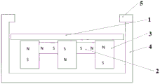
其中,1-阴极靶,2-横向磁体,3-纵向磁体,4-磁屏蔽层,5-导磁组件。Among them, 1-cathode target, 2-transverse magnet, 3-longitudinal magnet, 4-magnetic shielding layer, 5-magnetic conductive component.
具体实施方式Detailed ways
为更好地说明本实用新型,便于理解本实用新型的技术方案,下面对本实用新型进一步详细说明,但下述的实施例仅是本实用新型的简易例子,并不代表或限制本实用新型的权利保护范围,本实用新型保护范围以权利要求书为准。In order to better illustrate the present utility model and facilitate the understanding of the technical solutions of the present utility model, the present utility model is described in further detail below, but the following embodiments are only simple examples of the present utility model, and do not represent or limit the present utility model. The protection scope of the rights, the protection scope of the present invention is subject to the claims.
本实用新型具体实施方式部分提供了一种磁控溅射阴极的磁源结构,所述磁源结构包括阴极靶1和磁体组件,所述磁体组件设置于阴极靶1下方;The specific embodiment of the present invention partially provides a magnetic source structure of a magnetron sputtering cathode, the magnetic source structure includes a
所述磁体组件包括横向磁体2和纵向磁体3,所述横向磁体2和纵向磁体3交替排列,相邻的纵向磁体3的磁极相反,相邻的纵向磁体3和横向磁体2的磁极相同。The magnet assembly includes transverse magnets 2 and
以下为本实用新型典型但非限制性实施例:The following are typical but non-limiting examples of the present utility model:
实施例1:Example 1:
本实施例提供了一种磁控溅射阴极的磁源结构,所述磁源结构的结构示意图如图1所示,包括阴极靶1和磁体组件,所述磁体组件设置于阴极靶1下方;The present embodiment provides a magnetic source structure for a magnetron sputtering cathode. A schematic structural diagram of the magnetic source structure is shown in FIG. 1 , including a
所述磁体组件包括横向磁体2和纵向磁体3,所述横向磁体2和纵向磁体3交替排列,相邻的纵向磁体3的磁极相反,相邻的纵向磁体3和横向磁体2的磁极相同。The magnet assembly includes transverse magnets 2 and
所述磁体为条形磁体,材质为烧结钕铁硼。The magnet is a bar magnet, and the material is sintered NdFeB.
所述横向磁体2可在相邻两个纵向磁体3的间隔区域内沿纵向移动;所述横向磁体2的移动距离为纵向磁体3高度的3/8。The transverse magnet 2 can move in the longitudinal direction within the interval area between two adjacent
所述横向磁体2与水平方向的夹角为0度,所述纵向磁体3与竖直方向的夹角为0度。The angle between the transverse magnet 2 and the horizontal direction is 0 degree, and the angle between the
所述阴极靶1为平面靶,所述阴极靶1为圆形靶材,所述纵向磁体3包括中间磁体和环绕中间磁体的外圈磁体,所述外圈磁体设有一圈,所述外圈磁体与中间磁体之间对应设有一圈横向磁体2。The
所述磁源结构还包括底座,所述磁体组件设置于底座上。The magnetic source structure further includes a base, and the magnet assembly is arranged on the base.
所述磁源结构的四周和底侧设有磁屏蔽层4,所述磁屏蔽层4不与磁源结构直接接触。A
所述磁源结构还包括导磁组件5,所述导磁组件5设置于所述阴极靶1的侧上方,并设置于磁屏蔽层4侧面上方。The magnetic source structure further includes a magnetic
实施例2:Example 2:
本实施例提供了一种磁控溅射阴极的磁源结构,所述磁源结构包括阴极靶1和磁体组件,所述磁体组件设置于阴极靶1下方;This embodiment provides a magnetic source structure of a magnetron sputtering cathode, the magnetic source structure includes a
所述磁体组件包括横向磁体2和纵向磁体3,所述横向磁体2和纵向磁体3交替排列,相邻的纵向磁体3的磁极相反,相邻的纵向磁体3和横向磁体2的磁极相同。The magnet assembly includes transverse magnets 2 and
所述磁体为条形磁体,材质为烧结铁氧体。The magnet is a bar magnet, and the material is sintered ferrite.
所述横向磁体2可在相邻两个纵向磁体3的间隔区域内沿纵向移动;所述横向磁体2的移动距离为纵向磁体3高度的1/4。The transverse magnet 2 can move longitudinally in the interval area between two adjacent
所述横向磁体2与水平方向的夹角为2度,所述纵向磁体3与竖直方向的夹角为2度。The angle between the transverse magnet 2 and the horizontal direction is 2 degrees, and the angle between the
所述阴极靶1为平面靶,所述阴极靶1为圆形靶材,所述纵向磁体3包括中间磁体和环绕中间磁体的外圈磁体,所述外圈磁体设有两圈,相邻两圈外圈磁体之间以及所述外圈磁体与中间磁体之间对应各设有一圈横向磁体2。The
所述磁源结构还包括底座,所述磁体组件设置于底座上。The magnetic source structure further includes a base, and the magnet assembly is arranged on the base.
所述磁源结构的四周和底侧设有磁屏蔽层4,所述磁屏蔽层4不与磁源结构直接接触。A
实施例3:Example 3:
本实施例提供了一种磁控溅射阴极的磁源结构,所述磁源结构包括阴极靶1和磁体组件,所述磁体组件设置于阴极靶1下方;This embodiment provides a magnetic source structure of a magnetron sputtering cathode, the magnetic source structure includes a
所述磁体组件包括横向磁体2和纵向磁体3,所述横向磁体2和纵向磁体3交替排列,相邻的纵向磁体3的磁极相反,相邻的纵向磁体3和横向磁体2的磁极相同。The magnet assembly includes transverse magnets 2 and
所述磁体为条形磁体,材质为烧结钐钴。The magnet is a bar magnet, and the material is sintered samarium cobalt.
所述横向磁体2可在相邻两个纵向磁体3的间隔区域内沿纵向移动;所述横向磁体2的移动距离为纵向磁体3高度的1/8。The transverse magnet 2 can move in the longitudinal direction within the interval area between two adjacent
所述横向磁体2与水平方向的夹角为5度,所述纵向磁体3与竖直方向的夹角为5度。The included angle between the transverse magnet 2 and the horizontal direction is 5 degrees, and the included angle between the
所述阴极靶1为平面靶,所述阴极靶1为矩形靶材,所述纵向磁体3包括中间磁体和围绕中间磁体的外周磁体,所述外周磁体设有一周,所述外周磁体与中间磁体之间对应设有一周横向磁体2。The
所述磁源结构还包括底座,所述磁体组件设置于底座上。The magnetic source structure further includes a base, and the magnet assembly is arranged on the base.
所述磁源结构的四周和底侧设有磁屏蔽层4,所述磁屏蔽层4不与磁源结构直接接触。A
所述磁源结构还包括导磁组件5,所述导磁组件5设置于所述阴极靶1的侧上方,并设置于磁屏蔽层4侧面上方。The magnetic source structure further includes a magnetic
对比例1:Comparative Example 1:
本对比例提供了一种磁控溅射阴极的磁源结构,所述磁源结构的结构示意图如图2所示,其参照实施例1中的结构,区别仅在于:所述磁体组件不包括横向磁体2,只设有纵向磁体。This comparative example provides a magnetic source structure of a magnetron sputtering cathode. The schematic structural diagram of the magnetic source structure is shown in FIG. 2 , which refers to the structure in Example 1, the only difference is that the magnet assembly does not include The transverse magnet 2 is only provided with longitudinal magnets.
将实施例1和对比例中1的磁源结构组装后,模拟测定阴极靶表面的磁场水平分量,其结果如图3所示。After assembling the magnetic source structures of Example 1 and Comparative Example 1, the horizontal component of the magnetic field on the surface of the cathode target was simulated and measured, and the results are shown in FIG. 3 .
由图3可知,所述磁源结构中增加了横向磁体后,可以极大地增强阴极靶表面磁场水平分量。As can be seen from FIG. 3 , after the transverse magnet is added to the magnetic source structure, the horizontal component of the magnetic field on the surface of the cathode target can be greatly enhanced.
实施例4:Example 4:
本实施例提供了一种磁控溅射阴极磁源结构磁场的调节方法,所述磁源结构采用实施例1中的结构,所述方法包括:This embodiment provides a method for adjusting the magnetic field of a magnetron sputtering cathode magnetic source structure, where the magnetic source structure adopts the structure in
(1)按照实施例1中的磁源结构进行组装,磁体组件采用机械固定的方式排列组装,所述阴极靶1的直径为40mm,固定横向磁体2的初始位置,使得阴极靶1面附近磁场水平分量均匀;(1) Assemble according to the magnetic source structure in Example 1. The magnet assemblies are arranged and assembled in a mechanically fixed manner. The diameter of the
(2)随着磁控溅射进行过程中,磁体组件整体旋转,阴极靶1厚度减小,沿纵向调整横向磁体2的位置,调节阴极靶1面附近磁场水平分量的大小并维持均匀。(2) During the magnetron sputtering process, the magnet assembly rotates as a whole, the thickness of the
对比例2:Comparative Example 2:
本对比例提供了一种磁控溅射阴极磁源结构磁场的调节方法,所述磁源结构采用实施例1中的结构,所述方法参照实施例4中的方法,区别仅在于:步骤(2)中随着溅射过程进行,沿纵向调节磁体组件整体的位置。This comparative example provides a method for adjusting the magnetic field of a magnetron sputtering cathode magnetic source structure, the magnetic source structure adopts the structure in Example 1, and the method refers to the method in Example 4, the difference only lies in: the steps ( 2) As the sputtering process proceeds, the overall position of the magnet assembly is adjusted in the longitudinal direction.
对比例3:Comparative Example 3:
本对比例提供了一种磁控溅射阴极磁源结构磁场的调节方法,所述磁源结构采用对比例1中的结构,所述方法包括:This comparative example provides a method for adjusting the magnetic field of a magnetron sputtering cathode magnetic source structure, the magnetic source structure adopts the structure in Comparative Example 1, and the method includes:
(1)按照对比例1中的磁源结构进行组装,磁体组件采用机械固定的方式排列组装,所述阴极靶1的直径为40mm;(1) Assemble according to the magnetic source structure in Comparative Example 1, the magnet assemblies are arranged and assembled in a mechanically fixed manner, and the diameter of the
(2)随着磁控溅射进行过程中,磁体组件整体旋转,阴极靶1厚度减小,沿纵向调整纵向磁体3的位置,调节阴极靶1面附近磁场水平分量的大小。(2) During the magnetron sputtering process, the magnet assembly rotates as a whole, the thickness of the
将实施例4和对比例2-3中溅射进行过程中,及时反馈调整磁体位置后,模拟测定阴极靶表面的磁场水平分量,其结果如图4所示。During the sputtering in Example 4 and Comparative Examples 2-3, after timely feedback and adjustment of the magnet position, the horizontal component of the magnetic field on the surface of the cathode target was simulated and measured, and the results are shown in FIG. 4 .
由图4可知,随着磁控溅射的进行,靶材厚度变薄后需要调整磁体的位置,实施例4中单独调节横向磁体的效果要高于对比例2中调节磁体组件整体的效果,而对比例3中只能调节纵向磁体的位置,其磁场强度最小。It can be seen from Figure 4 that with the progress of magnetron sputtering, the position of the magnet needs to be adjusted after the thickness of the target becomes thinner. In Comparative Example 3, only the position of the longitudinal magnet can be adjusted, and its magnetic field strength is the smallest.
综合上述实施例和对比例可以看出,本实用新型所述磁源结构通过在常规磁体的基础上增加横向磁体,并通过横向磁体和纵向磁体的排列方式,有效增强阴极靶表面附近的磁场强度;所述磁源结构中横向磁体位置的可调节性,可有效改变靶材表面磁场的分布情况,增强磁场分布的均匀性和一致性,使磁控溅射进行时靶材能够均匀消耗,提高镀膜质量。Combining the above embodiments and comparative examples, it can be seen that the magnetic source structure of the present invention effectively enhances the magnetic field intensity near the surface of the cathode target by adding transverse magnets on the basis of conventional magnets, and through the arrangement of transverse magnets and longitudinal magnets ; The adjustability of the position of the transverse magnet in the magnetic source structure can effectively change the distribution of the magnetic field on the surface of the target material, enhance the uniformity and consistency of the magnetic field distribution, so that the target material can be uniformly consumed during magnetron sputtering, improving coating quality.
申请人声明,本实用新型通过上述实施例来说明本实用新型的详细结构,但本实用新型并不局限于上述详细结构,即不意味着本实用新型必须依赖上述详细结构才能实施。所属技术领域的技术人员应该明了,对本实用新型的任何改进,对本实用新型结构的等效替换及辅助结构的添加、具体方式的选择等,均落在本实用新型的保护范围和公开范围之内。The applicant declares that the present utility model illustrates the detailed structure of the present utility model through the above-mentioned embodiments, but the present utility model is not limited to the above-mentioned detailed structure, that is, it does not mean that the present utility model must rely on the above-mentioned detailed structure to be implemented. Those skilled in the art should understand that any improvement of the present invention, equivalent replacement of the structure of the present invention, addition of auxiliary structures, selection of specific methods, etc., all fall within the scope of protection and disclosure of the present invention. .
Claims (10)
Priority Applications (1)
| Application Number | Priority Date | Filing Date | Title |
|---|---|---|---|
| CN201922313233.8U CN211112196U (en) | 2019-12-20 | 2019-12-20 | A magnetic source structure of magnetron sputtering cathode |
Applications Claiming Priority (1)
| Application Number | Priority Date | Filing Date | Title |
|---|---|---|---|
| CN201922313233.8U CN211112196U (en) | 2019-12-20 | 2019-12-20 | A magnetic source structure of magnetron sputtering cathode |
Publications (1)
| Publication Number | Publication Date |
|---|---|
| CN211112196U true CN211112196U (en) | 2020-07-28 |
Family
ID=71701750
Family Applications (1)
| Application Number | Title | Priority Date | Filing Date |
|---|---|---|---|
| CN201922313233.8U Active CN211112196U (en) | 2019-12-20 | 2019-12-20 | A magnetic source structure of magnetron sputtering cathode |
Country Status (1)
| Country | Link |
|---|---|
| CN (1) | CN211112196U (en) |
Cited By (2)
| Publication number | Priority date | Publication date | Assignee | Title |
|---|---|---|---|---|
| CN110791742A (en) * | 2019-12-20 | 2020-02-14 | 横店集团东磁股份有限公司 | Magnetic source structure of magnetron sputtering cathode and method for adjusting magnetic field |
| CN114032516A (en) * | 2021-07-07 | 2022-02-11 | 重庆康佳光电技术研究院有限公司 | Magnetic source module for magnetron sputtering equipment and magnetron sputtering equipment |
-
2019
- 2019-12-20 CN CN201922313233.8U patent/CN211112196U/en active Active
Cited By (3)
| Publication number | Priority date | Publication date | Assignee | Title |
|---|---|---|---|---|
| CN110791742A (en) * | 2019-12-20 | 2020-02-14 | 横店集团东磁股份有限公司 | Magnetic source structure of magnetron sputtering cathode and method for adjusting magnetic field |
| CN114032516A (en) * | 2021-07-07 | 2022-02-11 | 重庆康佳光电技术研究院有限公司 | Magnetic source module for magnetron sputtering equipment and magnetron sputtering equipment |
| CN114032516B (en) * | 2021-07-07 | 2023-12-22 | 重庆康佳光电科技有限公司 | Magnetic source module for magnetron sputtering equipment and magnetron sputtering equipment |
Similar Documents
| Publication | Publication Date | Title |
|---|---|---|
| CN110791742A (en) | Magnetic source structure of magnetron sputtering cathode and method for adjusting magnetic field | |
| EP0600070B1 (en) | Improved planar magnetron sputtering magnet assembly | |
| US4892633A (en) | Magnetron sputtering cathode | |
| US4865708A (en) | Magnetron sputtering cathode | |
| US6432285B1 (en) | Planar magnetron sputtering apparatus | |
| CN211112196U (en) | A magnetic source structure of magnetron sputtering cathode | |
| CN115011941B (en) | Permanent magnet selective coating method based on variable magnetic field magnetron sputtering coating device | |
| CN115505890B (en) | Magnetron sputtering planar cathode and magnetic circuit thereof | |
| CN204162777U (en) | A kind of target material assembly | |
| CN107400869A (en) | A kind of method of flat target utilization rate during raising magnetron sputtering plating | |
| CN109841468B (en) | Magnetron assembly, magnetron sputtering chamber and semiconductor processing equipment | |
| CN107151784B (en) | A kind of cathode magnetron sputtering target assembly | |
| CN201336198Y (en) | Magnetic circuit mechanism and magnetron sputtering cathode with same | |
| JPH0352535B2 (en) | ||
| KR100963413B1 (en) | Magnetron sputtering device | |
| JPH04276069A (en) | Sputtering method and device | |
| CN217459573U (en) | Rotary cathode magnetic rod for magnetron sputtering and magnetron | |
| CN111996504A (en) | Ferromagnetic target magnetron sputtering device | |
| JP2789251B2 (en) | Sputtering equipment using dipole ring type magnetic circuit | |
| JPH0517869A (en) | Sputtering method and device | |
| JP3778501B2 (en) | Sputtering apparatus and sputtering method | |
| TW201807232A (en) | Magnetic target cathode device with high rate of target utilization capable of effectively increasing the rate of target utilization by enlarging the area of a bombardment surface | |
| JPH04318165A (en) | Sputtering method and system therefor | |
| JPH05179440A (en) | Magnetron type sputter cathode | |
| JPH04235277A (en) | Sputtering method and device |
Legal Events
| Date | Code | Title | Description |
|---|---|---|---|
| GR01 | Patent grant | ||
| GR01 | Patent grant |