CN210788889U - Stamping die convenient to automatic transport - Google Patents
Stamping die convenient to automatic transport Download PDFInfo
- Publication number
- CN210788889U CN210788889U CN201921701375.5U CN201921701375U CN210788889U CN 210788889 U CN210788889 U CN 210788889U CN 201921701375 U CN201921701375 U CN 201921701375U CN 210788889 U CN210788889 U CN 210788889U
- Authority
- CN
- China
- Prior art keywords
- movable rod
- rod
- push
- push rod
- die
- Prior art date
- Legal status (The legal status is an assumption and is not a legal conclusion. Google has not performed a legal analysis and makes no representation as to the accuracy of the status listed.)
- Expired - Fee Related
Links
- 238000004080 punching Methods 0.000 abstract description 7
- 238000003754 machining Methods 0.000 abstract description 5
- 238000000034 method Methods 0.000 description 2
- 238000012545 processing Methods 0.000 description 2
- 230000001360 synchronised effect Effects 0.000 description 2
- 230000001174 ascending effect Effects 0.000 description 1
- 230000009286 beneficial effect Effects 0.000 description 1
- 150000001875 compounds Chemical class 0.000 description 1
- 238000013461 design Methods 0.000 description 1
- 238000011161 development Methods 0.000 description 1
- 238000009826 distribution Methods 0.000 description 1
- 238000009776 industrial production Methods 0.000 description 1
- 239000002184 metal Substances 0.000 description 1
- 238000012986 modification Methods 0.000 description 1
- 230000004048 modification Effects 0.000 description 1
- 230000001737 promoting effect Effects 0.000 description 1
- 230000000630 rising effect Effects 0.000 description 1
Images



Landscapes
- Press Drives And Press Lines (AREA)
Abstract
The utility model discloses a stamping die convenient to automatic transport, include telescopic cylinder, push pedal, go up mould and second conveyer belt, telescopic cylinder installs the up end at the base, the interior bottom surface at the lower mould is installed in the push pedal, go up the mould and install the below at the lower mould, telescopic cylinder's output and the end department of push rod link to each other, and the avris of push rod is provided with the ball, first movable rod is installed to the top of push rod, and the end department of first movable rod is fixed with the spring, the outside cover of first movable rod is equipped with the fixed plate, the avris of first movable rod passes through connecting rod and second movable rod and links to each other, the opposite side at the lower mould is installed to the second conveyer belt. This stamping die convenient to automatic transport, before the mould punching press and after accomplishing the punching press, the realization work piece that can be automatic place and take, reduced the labour that artifical manual operation need consume, and then promoted stamping die's practicality and machining efficiency.
Description
Technical Field
The utility model relates to a stamping die technical field specifically is a stamping die convenient to automatic transport.
Background
Stamping die is one of numerous mould types, and the metalwork processing field in industrial production is comparatively common, and its essence is through the compound die punching press action between last mould and the lower mould, realizes the rapid prototyping's of metal work piece modernized processing equipment, has played the important function that improves mechanical efficiency, and along with the continuous development in the machining field, people also are more and more high to stamping die's functional requirement, but current stamping die has following shortcoming when in-service use:
before the mould punching press and after accomplishing the punching press, its inside work piece needs the manual operation repeatedly, just can realize taking of work piece and place the operation, does not possess corresponding automatic function of carrying, the reduction stamping die's of great degree practicality and machining efficiency to above-mentioned problem, need to carry out the innovative design on original stamping die's basis urgently.
SUMMERY OF THE UTILITY MODEL
An object of the utility model is to provide a stamping die convenient to automatic transport to solve before above-mentioned background art proposes the mould punching press and accomplish the punching press after, its inside work piece needs the manual operation of artifical relapse, just can realize taking of work piece and place the operation, does not possess corresponding automatic function of carrying, the great reduction stamping die's practicality and machining efficiency's problem.
In order to achieve the above object, the utility model provides a following technical scheme: a stamping die convenient for automatic conveying comprises a telescopic cylinder, a push plate, an upper die and a second conveyor belt, wherein the telescopic cylinder is arranged on the upper end surface of a base, and the top of the telescopic cylinder is provided with a lower die, the push plate is arranged on the inner bottom surface of the lower die, a workpiece is placed on the upper end surface of the push plate, the upper die is arranged below the lower die, and one side of the lower die is provided with a first conveyor belt, the output end of the telescopic cylinder is connected with the end of the push rod, the side of the push rod is provided with a ball, a first movable rod is arranged above the push rod, a spring is fixed at the end of the first movable rod, a fixed plate is sleeved outside the first movable rod, a through groove is arranged inside the fixed plate, and the bottom of the fixed plate is connected with the base through a supporting rod, the side of the first movable rod is connected with the second movable rod through a connecting rod, and the second conveyor belt is arranged on the other side of the lower die.
Preferably, the highest points of the lower die and the first conveyor belt are located on the same horizontal plane, the highest point of the lower die is lower than the highest point of the second conveyor belt, and the height of the second conveyor belt is lower than the height of the connecting rod.
Preferably, the balls are distributed on the push rod at equal intervals, the balls and the push rod form a relative rotation structure, the push rod is arranged in an inclined mode, and the highest point of the push rod is higher than the lowest point of the first movable rod.
Preferably, the first movable rod is of a C-shaped structure, and the first movable rod and the fixed plate form a sliding structure through the through groove.
Preferably, the number of the fixed plates is 3, the fixed plates far away from the push rod are in sliding connection with the second movable rod, the second movable rod is of an inverted L-shaped structure, and the distance between the two transversely-distributed fixed plates is larger than the width of the upper die.
Compared with the prior art, the beneficial effects of the utility model are that: according to the stamping die convenient for automatic conveying, before stamping and after stamping of the die, the workpiece can be automatically placed and taken, labor force consumed by manual operation is reduced, and the practicability and the machining efficiency of the stamping die are improved;
1. the telescopic cylinder pushes the push plate to push out the punched workpiece, and simultaneously can drive the push rod to synchronously ascend so as to drive the first movable rod to slide in the through groove and drive the connecting rod to move, so that the unprocessed workpiece on the second conveying belt is pushed onto the push plate, and the product of the push plate is synchronously pushed onto the first conveying belt;
2. the ball can be driven to roll when the first movable rod is in contact with the push rod, so that the resistance of the first movable rod when the first movable rod moves is reduced, the second movable rod can be driven to move synchronously through the connecting rod, the stability of the connecting rod for pushing a workpiece to move is further improved, and the movable rod can be driven to automatically restore to the initial position when the push rod is not pushed due to the arrangement of the spring.
Drawings
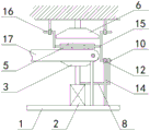
FIG. 1 is a schematic front view of the present invention;
FIG. 2 is a schematic side view of the present invention;
FIG. 3 is an enlarged schematic view of the structure at A of FIG. 1 according to the present invention;
fig. 4 is a schematic view of the structure of the utility model after the movement of the push rod.
In the figure: 1. a base; 2. a telescopic cylinder; 3. a lower die; 4. pushing the plate; 5. a workpiece; 6. an upper die; 7. a first conveyor belt; 8. a push rod; 9. a ball bearing; 10. a first movable bar; 11. a spring; 12. a fixing plate; 13. a through groove; 14. a support bar; 15. a connecting rod; 16. a second movable bar; 17. a second conveyor belt.
Detailed Description
The technical solutions in the embodiments of the present invention will be described clearly and completely with reference to the accompanying drawings in the embodiments of the present invention, and it is obvious that the described embodiments are only some embodiments of the present invention, not all embodiments. Based on the embodiments in the present invention, all other embodiments obtained by a person skilled in the art without creative work belong to the protection scope of the present invention.
Referring to fig. 1-4, the present invention provides a technical solution: a stamping die convenient for automatic conveying comprises a base 1, a telescopic cylinder 2, a lower die 3, a push plate 4, a workpiece 5, an upper die 6, a first conveyor belt 7, a push rod 8, balls 9, a first movable rod 10, springs 11, a fixing plate 12, a through groove 13, a supporting rod 14, a connecting rod 15, a second movable rod 16 and a second conveyor belt 17, wherein the telescopic cylinder 2 is installed on the upper end face of the base 1, the top of the telescopic cylinder 2 is provided with the lower die 3, the push plate 4 is installed on the inner bottom face of the lower die 3, the workpiece 5 is placed on the upper end face of the push plate 4, the upper die 6 is installed below the lower die 3, one side of the lower die 3 is provided with the first conveyor belt 7, the output end of the telescopic cylinder 2 is connected with the end of the push rod 8, the side of the push rod 8 is provided with the balls 9, the first movable rod 10 is installed above the push rod 8, a fixed plate 12 is sleeved on the outer side of the first movable rod 10, a through groove 13 is formed in the fixed plate 12, the bottom of the fixed plate 12 is connected with the base 1 through a support rod 14, the side of the first movable rod 10 is connected with a second movable rod 16 through a connecting rod 15, and a second conveyor belt 17 is installed on the other side of the lower die 3;
the highest points of the lower die 3 and the first conveyor belt 7 are positioned on the same horizontal plane, the highest point of the lower die 3 is lower than the highest point of the second conveyor belt 17, and the height of the second conveyor belt 17 is lower than that of the connecting rod 15, so that when the connecting rod 15 pushes the unprocessed workpiece 5 onto the push plate 4, the processed workpiece 5 on the push plate 4 can be synchronously pushed onto the first conveyor belt 7;
the balls 9 are distributed on the push rod 8 at equal intervals, the push rod 8 and the push rod 8 form a relative rotation structure, the push rod 8 is arranged in an inclined mode, the highest point of the push rod 8 is higher than the lowest point of the first movable rod 10, the push rod 8 can push the first movable rod 10 to slide in the through groove 13 in the rising process, the first movable rod 10 is in contact with the balls 9 and drives the balls to roll when moving, and resistance in moving can be reduced;
first movable rod 10 is "C" font structure, and first movable rod 10 constitutes sliding structure through logical groove 13 and fixed plate 12, fixed plate 12 is provided with 3, and the fixed plate 12 and the second movable rod 16 of keeping away from push rod 8 are sliding connection, and second movable rod 16 is for invering "L" shape structure, 2 fixed plate 12 intervals of transverse distribution are greater than the width of last mould 6 simultaneously, synchronous drive connecting rod 15 and the removal of second movable rod 16 when first movable rod 10 removes, and then can realize promoting the purpose of work piece 5, stability when having increased the removal simultaneously.
The working principle is as follows: when the stamping die convenient for automatic conveying is used, as shown in fig. 1-4, firstly, after a workpiece 5 is stamped in the stamping die, the telescopic cylinder 2 pushes the workpiece 5 in the lower die 3 out by pushing the push plate 4, as shown in fig. 4, the output shaft of the telescopic cylinder 2 synchronously drives the push rod 8 to ascend, as the push rod 8 is obliquely arranged, the first movable rod 10 can be pushed to slide in the through groove 13 in the ascending process, as shown in fig. 3, the first movable rod 10 is contacted with the ball 9 and driven to roll when moving, the resistance when the first movable rod 10 moves can be reduced, as shown in fig. 2, the first movable rod 10 synchronously drives the connecting rod 15 and the second movable rod 16 to move when moving, and further, the workpiece 5 on the second conveyor belt 17 can be pushed to the push plate 4, the workpiece 5 on the push plate 4 is pushed to the first conveyor belt 7, and further, the synchronous feeding and blanking of the workpiece 5 are realized, without manual operation of a worker, as shown in fig. 1, through the arrangement of the spring 11, the push rod 8 can automatically drive the first movable rod 10 to return to the initial position when not pushing the first movable rod, so as to facilitate subsequent stamping operation.
Although the present invention has been described in detail with reference to the foregoing embodiments, it will be apparent to those skilled in the art that modifications may be made to the embodiments or portions thereof without departing from the spirit and scope of the invention.
Claims (5)
1. The utility model provides a stamping die convenient to automatic transport, includes telescopic cylinder (2), push pedal (4), goes up mould (6) and second conveyer belt (17), its characterized in that: the telescopic cylinder (2) is arranged on the upper end face of the base (1), the top of the telescopic cylinder (2) is provided with a lower die (3), the push plate (4) is arranged on the inner bottom face of the lower die (3), the upper end face of the push plate (4) is provided with a workpiece (5), the upper die (6) is arranged below the lower die (3), one side of the lower die (3) is provided with a first conveying belt (7), the output end of the telescopic cylinder (2) is connected with the end of the push rod (8), the side of the push rod (8) is provided with a ball (9), a first movable rod (10) is arranged above the push rod (8), a spring (11) is fixed at the end of the first movable rod (10), the outer side of the first movable rod (10) is sleeved with a fixed plate (12), a through groove (13) is formed in the fixed plate (12), and the bottom of the fixed plate (12) is connected with the base (1) through a support rod (14), the avris of first movable rod (10) passes through connecting rod (15) and second movable rod (16) and links to each other, the opposite side at lower mould (3) is installed in second conveyer belt (17).
2. The press die facilitating automatic conveyance according to claim 1, wherein: the highest points of the lower die (3) and the first conveyor belt (7) are located on the same horizontal plane, the highest point of the lower die (3) is lower than the highest point of the second conveyor belt (17), and the height of the second conveyor belt (17) is lower than that of the connecting rod (15).
3. The press die facilitating automatic conveyance according to claim 1, wherein: the balls (9) are distributed on the push rod (8) at equal intervals, the balls and the push rod form a relative rotation structure, the push rod (8) is arranged in an inclined mode, and meanwhile the highest point of the push rod (8) is higher than the lowest point of the first movable rod (10).
4. The press die facilitating automatic conveyance according to claim 1, wherein: the first movable rod (10) is of a C-shaped structure, and the first movable rod (10) and the fixed plate (12) form a sliding structure through the through groove (13).
5. The press die facilitating automatic conveyance according to claim 1, wherein: the number of the fixing plates (12) is 3, the fixing plates (12) far away from the push rod (8) are in sliding connection with the second movable rod (16), the second movable rod (16) is of an inverted L-shaped structure, and meanwhile the distance between the transversely distributed 2 fixing plates (12) is larger than the width of the upper die (6).
Priority Applications (1)
| Application Number | Priority Date | Filing Date | Title |
|---|---|---|---|
| CN201921701375.5U CN210788889U (en) | 2019-10-12 | 2019-10-12 | Stamping die convenient to automatic transport |
Applications Claiming Priority (1)
| Application Number | Priority Date | Filing Date | Title |
|---|---|---|---|
| CN201921701375.5U CN210788889U (en) | 2019-10-12 | 2019-10-12 | Stamping die convenient to automatic transport |
Publications (1)
| Publication Number | Publication Date |
|---|---|
| CN210788889U true CN210788889U (en) | 2020-06-19 |
Family
ID=71244550
Family Applications (1)
| Application Number | Title | Priority Date | Filing Date |
|---|---|---|---|
| CN201921701375.5U Expired - Fee Related CN210788889U (en) | 2019-10-12 | 2019-10-12 | Stamping die convenient to automatic transport |
Country Status (1)
| Country | Link |
|---|---|
| CN (1) | CN210788889U (en) |
-
2019
- 2019-10-12 CN CN201921701375.5U patent/CN210788889U/en not_active Expired - Fee Related
Similar Documents
| Publication | Publication Date | Title |
|---|---|---|
| CN211965671U (en) | Automatic blanking machine of stamping device | |
| CN207071610U (en) | Feeding and punching press one automation equipment | |
| CN105107910B (en) | Self-unloading punch press | |
| CN107377737B (en) | A kind of automobile parts stamping die | |
| CN209969422U (en) | Stamping equipment is used in bearing bush production | |
| CN212121404U (en) | A feeding mechanism in high superficial lift mould for five metals punching press | |
| CN210788889U (en) | Stamping die convenient to automatic transport | |
| CN218638352U (en) | Switch elastic sheet bending die | |
| CN207857685U (en) | Metal material belt punching mechanism | |
| CN202239290U (en) | A flip-chip punching die | |
| CN211588298U (en) | Mechanical feeding mechanism for dovetail clamp forming machining | |
| CN210160246U (en) | A mesh steel belt punching device | |
| CN220311457U (en) | Stamping equipment for automobile parts | |
| EP2441533A1 (en) | A tool for stamping workpieces and a method for sorting stamped workpieces | |
| CN208288766U (en) | A kind of sectional aluminum extruded material punching die | |
| CN213104129U (en) | Forming die of machine tool parts | |
| CN113926918B (en) | Progressive die system and progressive stamping process | |
| CN210876956U (en) | Stamping equipment of meson | |
| CN212554165U (en) | Garbage collection subassembly for punch press | |
| CN212419397U (en) | Push device after punching of cycloid wheel | |
| CN211803322U (en) | Channel steel punching device | |
| CN216705625U (en) | Trimming and punching compound die of pin row forging | |
| CN109453960B (en) | Feeding and oiling mechanism for bearing noise detection mechanism | |
| CN220760827U (en) | High-efficient feeding mechanism is used in metal punching press | |
| CN223518587U (en) | A chain plate punching die device for chain production |
Legal Events
| Date | Code | Title | Description |
|---|---|---|---|
| GR01 | Patent grant | ||
| GR01 | Patent grant | ||
| CF01 | Termination of patent right due to non-payment of annual fee |
Granted publication date: 20200619 Termination date: 20211012 |
|
| CF01 | Termination of patent right due to non-payment of annual fee |