CN210770219U - Sealing structure of magnetic stimulation coil - Google Patents
Sealing structure of magnetic stimulation coil Download PDFInfo
- Publication number
- CN210770219U CN210770219U CN201921435779.4U CN201921435779U CN210770219U CN 210770219 U CN210770219 U CN 210770219U CN 201921435779 U CN201921435779 U CN 201921435779U CN 210770219 U CN210770219 U CN 210770219U
- Authority
- CN
- China
- Prior art keywords
- sealing
- casing
- magnetic stimulation
- stimulation coil
- butt joint
- Prior art date
- Legal status (The legal status is an assumption and is not a legal conclusion. Google has not performed a legal analysis and makes no representation as to the accuracy of the status listed.)
- Active
Links
- 238000007789 sealing Methods 0.000 title claims abstract description 74
- 230000000638 stimulation Effects 0.000 title claims abstract description 53
- 210000001503 joint Anatomy 0.000 claims abstract description 23
- 238000003466 welding Methods 0.000 claims abstract description 15
- 239000000565 sealant Substances 0.000 claims 2
- 230000007547 defect Effects 0.000 abstract description 4
- 230000009286 beneficial effect Effects 0.000 abstract description 2
- 230000017525 heat dissipation Effects 0.000 abstract 1
- 239000007788 liquid Substances 0.000 description 35
- 238000001816 cooling Methods 0.000 description 21
- 230000000694 effects Effects 0.000 description 8
- 238000005192 partition Methods 0.000 description 3
- 239000002826 coolant Substances 0.000 description 2
- 238000010586 diagram Methods 0.000 description 2
- 238000005516 engineering process Methods 0.000 description 2
- 239000002184 metal Substances 0.000 description 2
- 229910052751 metal Inorganic materials 0.000 description 2
- 238000000034 method Methods 0.000 description 2
- 238000012986 modification Methods 0.000 description 2
- 230000004048 modification Effects 0.000 description 2
- 230000003068 static effect Effects 0.000 description 2
- RYGMFSIKBFXOCR-UHFFFAOYSA-N Copper Chemical compound [Cu] RYGMFSIKBFXOCR-UHFFFAOYSA-N 0.000 description 1
- 230000032683 aging Effects 0.000 description 1
- 230000003139 buffering effect Effects 0.000 description 1
- 238000005253 cladding Methods 0.000 description 1
- 239000011248 coating agent Substances 0.000 description 1
- 238000000576 coating method Methods 0.000 description 1
- 239000004020 conductor Substances 0.000 description 1
- 229910052802 copper Inorganic materials 0.000 description 1
- 239000010949 copper Substances 0.000 description 1
- 238000010438 heat treatment Methods 0.000 description 1
- 238000009413 insulation Methods 0.000 description 1
- 230000005389 magnetism Effects 0.000 description 1
- 230000002093 peripheral effect Effects 0.000 description 1
- 238000000926 separation method Methods 0.000 description 1
Images


Landscapes
- Magnetic Treatment Devices (AREA)
Abstract
The utility model discloses a magnetic stimulation coil's seal structure, including last casing, lower casing and magnetic stimulation coil, last casing and lower casing butt joint after form the cavity, magnetic stimulation coil set up in the cavity, a serial communication port, the lower casing still be provided with the seal ring groove on the surface of the butt joint face of last casing butt joint, the seal ring inslot be provided with the sealing washer, form first seal structure, and last casing form barb structure at the edge with the butt joint face of lower casing butt joint, and the corresponding end of casing then forms and last casing end structure complex slot down, barb structure buckle in the slot. The utility model discloses the beneficial effect who reaches: the defects of poor sealing property in the cavity are overcome by adopting three sealing modes of buckling connection of an upper shell and a lower shell, ultrasonic welding, sealing of a sealing ring, ultrasonic welding and sealing of a rubber sleeve; the circulating medium is directly introduced into the cavity, so that the heat dissipation efficiency is further improved.
Description
Technical Field
The utility model relates to a magnetic stimulation coil's seal structure, concretely relates to a seal structure for magnetic stimulation coil circulation liquid cooling belongs to medical instrument technical field.
Background
The magnetic field strength range of the current transcranial magnetic field stimulator system is concentrated, and the side effect of heat is easily generated due to the fact that the current strength in a stimulation coil is large. For the device, heating of the stimulation coil accelerates its aging process, reduces its lifetime, and treatment interruption cannot be continuous. The existing methods for solving the problems mainly comprise air cooling, static liquid cooling, dynamic liquid cooling and the like.
The former two have great technical defects, such as large air cooling noise, slow dissipation of static cooling heat and the like. The current mode of the dynamic liquid cooling is that a magnetic stimulation coil is of a tubular structure and is formed by coiling a tubular body, and a liquid cooling medium flows in the tubular coil, so that the stroke of the liquid cooling medium is very long, the cooling efficiency is low, and the effect is poor. The circulating medium is directly injected into the cavity, and the defects of poor sealing property and overflow risk exist. Therefore, the problem of poor sealing performance of the circulating liquid cooling is one of the important problems facing the present.
Disclosure of Invention
For solving the not enough of prior art, the utility model aims to provide a seal structure that is used for magnetic stimulation coil circulation liquid cooling that sealing performance is good.
In order to achieve the above object, the present invention adopts the following technical solutions:
the utility model provides a seal structure of magnetic stimulation coil, includes casing, lower casing and magnetic stimulation coil, last casing and lower casing butt joint after form the cavity, magnetic stimulation coil set up in the cavity, its characterized in that, lower casing still be provided with the seal ring groove on the surface of the butt joint face of last casing butt joint, the seal ring inslot be provided with the sealing washer, form first seal structure, and last casing form barb structure at the edge with the butt joint face of lower casing butt joint, and the corresponding end of casing then forms with last casing end structure complex slot down, barb structure press the buckle at the ditch inslot through the ultrasonic wave high frequency. The buckle structure effectively guarantees the locking of the sealing ring, ensures reliable sealing, and avoids the influence of screw locking on occupied space and metal on magnetic stimulation.
The sealing rings are arranged on the connecting end faces of the liquid inlet pipe, the liquid outlet pipe and the magnetic stimulation coil, the height of each sealing ring is larger than the depth of each sealing ring groove, and the sealing effect between the upper shell and the lower shell is guaranteed.
And the upper shell and the lower shell are also provided with welding sealing layers at the ends close to the magnetic stimulation coils of the butt joint surfaces, and a second sealing structure, namely an ultrasonic welding sealing layer, is formed by an ultrasonic welding technology.
And, foretell magnetic stimulation coil's seal structure still includes an annular rubber sleeve, annular rubber sleeve cladding be in last casing and lower casing butt joint face the periphery, form the third seal structure, when sealed, can also play the effect of buffering, avoiding the fracture when magnetic stimulation coil falls. The third sealing structure can be used together with the first sealing structure and the second sealing structure, and can also be combined and sealed with any one of the first sealing structure and the second sealing structure.
Compared with the prior art, the utility model, its beneficial effect is:
i) the defects of poor sealing property in the cavity are overcome by adopting the modes of buckling connection of the upper and lower shells, ultrasonic welding, sealing of the sealing ring and coating and sealing of the annular rubber sleeve;
ii) the excellent sealing performance of the cavity can lead the circulating medium to be directly introduced into the cavity to wrap the whole coil, so that the liquid flow is short and the effect is fast.
iii) the cooling mode of circulating liquid cooling is adopted to continuously take away the heat on the surface of the magnetic stimulation coil, so that the stimulation coil can be continuously cooled, the stimulation coil can be ensured to work below a temperature threshold value, and the system stability is improved.
Drawings
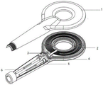
Fig. 1 is a schematic view of a split structure according to an embodiment of the present invention;
fig. 2 is a schematic structural diagram of a split state according to an embodiment of the present invention;
fig. 3 is a schematic view of the sealing structure of the present invention.
The meaning of the reference symbols in the figures:
1-upper shell, 2-magnetic stimulation coil, 3-insulating partition plate, 4-lower shell, 5-liquid inlet pipe and 6-liquid outlet pipe. 7-sealing cover, 8-tail ring, 9-sealing ring, 10-ultrasonic spot welding sealing layer, 11-barb structure and 12-annular rubber sleeve.
Detailed Description
The present invention will be further described with reference to the accompanying drawings. The following examples are only for illustrating the technical solutions of the present invention more clearly, and the protection scope of the present invention is not limited thereby.
For the external structure of the magnetic stimulation coil, in order to adjust the temperature of the magnetic stimulation coil, circulating liquid cooling and circulating air cooling are generally used, and of course, the circulating liquid cooling is used herein, a circulating medium directly wraps the magnetic stimulation coil, and the treatment after the circulating medium is used is a known technology, and is not described in detail by the applicant.
The application focuses on a sealing mode that a circulating medium for circulating liquid cooling directly wraps a magnetic stimulation coil.
Fig. 1 is a schematic structural view of a split body according to an embodiment of the present invention.
Referring to fig. 1, a circulating liquid cooling system for a magnetic stimulation coil, comprising: 1-upper shell, 2-magnetic stimulation coil, 3-insulation separation sheet, 4-lower shell, 5-liquid inlet pipe, 6-liquid outlet pipe, 7-cavity sealing ring, 8-tail ring, 9-sealing ring, 10-ultrasonic spot welding sealing layer, 11-buckle and 12-annular rubber sleeve.
The concrete structure sets up as: the upper shell 1 and the lower shell 4 are mutually butted through a buckle 11 to form a closed cavity, the magnetic stimulation coil 2 is arranged in the cavity, and cavity sealing rings 7 are arranged on the inner wall surface and the outer peripheral surface of the magnetic stimulation coil 2 and used for deepening sealing of the magnetic stimulation coil 2. The liquid inlet pipe 5 and the liquid outlet pipe 6 are made of conductive materials (copper pipes), are directly welded on two ends of the magnetic stimulation coil 2 through welding sheets, and form a conductive current loop with the magnetic stimulation coil 2; the insulating partition plate 3 is arranged between the liquid inlet pipe 5 and the liquid outlet pipe 6, so that the stroke of a circulating medium in the liquid inlet pipe 5 is ensured to surround a circle along the annular structure of the magnetic stimulation coil 2 and then flows out through the liquid outlet pipe 6, and the tail ring 8 is connected to the tail end of the handle of the upper shell 1 and the handle of the lower shell 4 in a ring mode to further fix the upper shell 1 and the lower shell 4.
Fig. 2 is a schematic structural diagram of a split state according to an embodiment of the present invention; fig. 3 is a schematic view of the sealing structure of the present invention.
As shown in fig. 2 and 3: the sealing structure of the magnetic stimulation coil in the circulating liquid cooling system for the magnetic stimulation coil comprises a multilayer sealing mechanism, and specifically comprises the following components from inside to outside: the upper shell 1 and the lower shell 4 are pressed and butted at the end close to the magnetic stimulation coil 2 of the butting surface in an ultrasonic high-frequency welding mode to form a welding sealing layer, and a first sealing, namely an ultrasonic welding sealing layer (a second sealing structure) is formed; outwards, the surface of the butt joint surface of the lower shell 4 is also provided with a sealing ring groove, a sealing ring 9 is arranged in the sealing ring groove to form a first sealing structure, the height of the sealing ring 9 is greater than the depth of the sealing ring groove to realize interference fit, and the sealing effect is good; outwards again, go up casing 1 and form barb structure 11 at the edge of the butt joint face with lower casing 4 butt joint, and lower casing 4's the end that corresponds then is formed with the 1 terminal surface structure complex slot of last casing, and barb structure 11 presses the buckle in the slot through the ultrasonic wave high frequency, and the locking of sealing washer 9 has effectively been guaranteed to buckle structure, makes sealed reliable, avoids adopting screw locking occupation space and metal to the amazing influence of magnetism.
And in order to further strengthen the sealing effect, after the butt joint of the upper shell 1 and the lower shell 4 is completed, the annular rubber sleeve 12 is coated on the periphery of the butt joint surface of the upper shell 1 and the lower shell 4 to form a third sealing structure, and the annular rubber sleeve 12 is made of soft rubber, so that the racket head can be prevented from being collided and broken when being sealed, and the racket head can be effectively protected.
The utility model discloses an operation process does: through three seals and the locking of a buckle structure, the sealed effect of the cavity that forms after realizing last casing and lower casing butt joint is excellent. The circulating medium (in this embodiment, the circulating medium is insulating liquid) flows in from the liquid inlet pipe 5 and directly enters the cavity formed by the upper shell 1 and the lower shell 4, and because the insulating partition sheet 3 is arranged between the liquid inlet pipe 5 and the liquid outlet pipe 6 at the position of entering the cavity, the circulating medium does not directly flow out from the liquid outlet pipe 6 in a short circuit mode, but flows out from the liquid outlet pipe 6 after flowing around the magnetic stimulation coil 2 along the surrounding route of the magnetic stimulation coil 2, so that the whole magnetic stimulation coil 2 is immersed in the circulating medium, and meanwhile, heat generated when the magnetic stimulation coil 3 works is taken away, cooling of the magnetic stimulation coil 2 can be rapidly realized, the magnetic stimulation coil 2 can be ensured to work below a temperature threshold, and stability and continuity of the system are improved.
In conclusion, the sealing structure of the utility model is simple, the product is sealed by three sealing structures and one locking structure, and the sealing performance of the product is ensured; in addition, the product adopts the circulating liquid cooling to directly inject the circulating medium into the cavity, so that the current sealing property meets the requirement of the product, and the stability and the continuity of the circulating liquid cooling of the system are improved.
The foregoing is only a preferred embodiment of the present invention, and it should be noted that, for those skilled in the art, a plurality of modifications and variations can be made without departing from the technical principle of the present invention, and these modifications and variations should also be considered as the protection scope of the present invention.
Claims (6)
1. The utility model provides a seal structure of magnetic stimulation coil, its characterized in that includes casing, lower casing and magnetic stimulation coil, last casing and casing butt joint down after form the cavity, magnetic stimulation coil set up in the cavity, lower casing still be provided with the seal ring groove on the surface of the butt joint face of last casing butt joint, the seal ring inslot be provided with the sealing washer, form first seal structure, and last casing form barb structure at the edge with the butt joint face of casing butt joint down, and the corresponding end of casing then forms with last casing end structure complex slot down, barb structure buckle in the ditch inslot.
2. A sealing structure of a magnetic stimulation coil according to claim 1, wherein the height of the sealing ring is greater than the depth of the sealing ring groove.
3. A sealing structure for a magnetic stimulation coil according to claim 1 or 2, wherein the upper housing and the lower housing are further formed with a welding sealing layer at the end of the abutting surface near the magnetic stimulation coil to form a second sealing structure.
4. A sealing structure for a magnetic stimulation coil according to claim 3, wherein the welding sealant is an ultrasonic welding sealant.
5. A sealing structure of a magnetic stimulation coil according to claim 1, further comprising an annular rubber sleeve, wherein the annular rubber sleeve is wrapped around the abutting surface of the upper casing and the lower casing to form a third sealing structure.
6. A sealing structure of a magnetic stimulation coil according to claim 3, characterized by further comprising an annular rubber sleeve, wherein the annular rubber sleeve is wrapped around the abutting surface of the upper casing and the lower casing to form a third sealing structure.
Priority Applications (1)
| Application Number | Priority Date | Filing Date | Title |
|---|---|---|---|
| CN201921435779.4U CN210770219U (en) | 2019-08-31 | 2019-08-31 | Sealing structure of magnetic stimulation coil |
Applications Claiming Priority (1)
| Application Number | Priority Date | Filing Date | Title |
|---|---|---|---|
| CN201921435779.4U CN210770219U (en) | 2019-08-31 | 2019-08-31 | Sealing structure of magnetic stimulation coil |
Publications (1)
| Publication Number | Publication Date |
|---|---|
| CN210770219U true CN210770219U (en) | 2020-06-16 |
Family
ID=71048098
Family Applications (1)
| Application Number | Title | Priority Date | Filing Date |
|---|---|---|---|
| CN201921435779.4U Active CN210770219U (en) | 2019-08-31 | 2019-08-31 | Sealing structure of magnetic stimulation coil |
Country Status (1)
| Country | Link |
|---|---|
| CN (1) | CN210770219U (en) |
Cited By (17)
| Publication number | Priority date | Publication date | Assignee | Title |
|---|---|---|---|---|
| US11794029B2 (en) | 2016-07-01 | 2023-10-24 | Btl Medical Solutions A.S. | Aesthetic method of biological structure treatment by magnetic field |
| US11806528B2 (en) | 2020-05-04 | 2023-11-07 | Btl Healthcare Technologies A.S. | Device and method for unattended treatment of a patient |
| US11826565B2 (en) | 2020-05-04 | 2023-11-28 | Btl Healthcare Technologies A.S. | Device and method for unattended treatment of a patient |
| US11878162B2 (en) | 2016-05-23 | 2024-01-23 | Btl Healthcare Technologies A.S. | Systems and methods for tissue treatment |
| US11883643B2 (en) | 2016-05-03 | 2024-01-30 | Btl Healthcare Technologies A.S. | Systems and methods for treatment of a patient including RF and electrical energy |
| US11896816B2 (en) | 2021-11-03 | 2024-02-13 | Btl Healthcare Technologies A.S. | Device and method for unattended treatment of a patient |
| US12064163B2 (en) | 2021-10-13 | 2024-08-20 | Btl Medical Solutions A.S. | Methods and devices for aesthetic treatment of biological structures by radiofrequency and magnetic energy |
| US12076576B2 (en) | 2019-04-11 | 2024-09-03 | Btl Medical Solutions A.S. | Methods and devices for aesthetic treatment of biological structures by radiofrequency and magnetic energy |
| US12109427B2 (en) | 2016-07-01 | 2024-10-08 | Btl Medical Solutions A.S. | Aesthetic method of biological structure treatment by magnetic field |
| US12109426B2 (en) | 2016-05-10 | 2024-10-08 | Btl Medical Solutions A.S. | Aesthetic method of biological structure treatment by magnetic field |
| US12156689B2 (en) | 2019-04-11 | 2024-12-03 | Btl Medical Solutions A.S. | Methods and devices for aesthetic treatment of biological structures by radiofrequency and magnetic energy |
| US12274494B2 (en) | 2016-08-16 | 2025-04-15 | Btl Healthcare Technologies A.S. | Treatment device |
| US12521562B2 (en) | 2016-05-03 | 2026-01-13 | Btl Healthcare Technologies A.S. | Device including RF source of energy and vacuum system |
| US12558146B2 (en) | 2019-04-11 | 2026-02-24 | Btl Medical Solutions A.S. | Methods and devices for aesthetic treatment of biological structures by radiofrequency and magnetic energy |
| US12564726B1 (en) | 2024-10-08 | 2026-03-03 | Btl Medical Solutions A.S. | Devices and methods for application of a magnetic field to the nervous system |
| US12589256B2 (en) | 2016-05-10 | 2026-03-31 | Btl Medical Solutions A.S. | Aesthetic method of biological structure treatment by magnetic field |
| US12611545B2 (en) | 2020-05-04 | 2026-04-28 | Btl Healthcare Technologies A.S. | Device and method for unattended treatment of a patient |
-
2019
- 2019-08-31 CN CN201921435779.4U patent/CN210770219U/en active Active
Cited By (27)
| Publication number | Priority date | Publication date | Assignee | Title |
|---|---|---|---|---|
| US12521562B2 (en) | 2016-05-03 | 2026-01-13 | Btl Healthcare Technologies A.S. | Device including RF source of energy and vacuum system |
| US11883643B2 (en) | 2016-05-03 | 2024-01-30 | Btl Healthcare Technologies A.S. | Systems and methods for treatment of a patient including RF and electrical energy |
| US12589256B2 (en) | 2016-05-10 | 2026-03-31 | Btl Medical Solutions A.S. | Aesthetic method of biological structure treatment by magnetic field |
| US12151120B2 (en) | 2016-05-10 | 2024-11-26 | Btl Medical Solutions A.S. | Aesthetic method of biological structure treatment by magnetic field |
| US12109426B2 (en) | 2016-05-10 | 2024-10-08 | Btl Medical Solutions A.S. | Aesthetic method of biological structure treatment by magnetic field |
| US11896821B2 (en) | 2016-05-23 | 2024-02-13 | Btl Healthcare Technologies A.S. | Systems and methods for tissue treatment |
| US11878162B2 (en) | 2016-05-23 | 2024-01-23 | Btl Healthcare Technologies A.S. | Systems and methods for tissue treatment |
| US12109427B2 (en) | 2016-07-01 | 2024-10-08 | Btl Medical Solutions A.S. | Aesthetic method of biological structure treatment by magnetic field |
| US12521565B2 (en) | 2016-07-01 | 2026-01-13 | Btl Medical Solutions A.S. | Aesthetic method of biological structure treatment by magnetic field |
| US11794029B2 (en) | 2016-07-01 | 2023-10-24 | Btl Medical Solutions A.S. | Aesthetic method of biological structure treatment by magnetic field |
| US12274494B2 (en) | 2016-08-16 | 2025-04-15 | Btl Healthcare Technologies A.S. | Treatment device |
| US12156689B2 (en) | 2019-04-11 | 2024-12-03 | Btl Medical Solutions A.S. | Methods and devices for aesthetic treatment of biological structures by radiofrequency and magnetic energy |
| US12076576B2 (en) | 2019-04-11 | 2024-09-03 | Btl Medical Solutions A.S. | Methods and devices for aesthetic treatment of biological structures by radiofrequency and magnetic energy |
| US12558146B2 (en) | 2019-04-11 | 2026-02-24 | Btl Medical Solutions A.S. | Methods and devices for aesthetic treatment of biological structures by radiofrequency and magnetic energy |
| US12558542B2 (en) | 2020-05-04 | 2026-02-24 | Btl Healthcare Technologies A.S. | Device and method for unattended treatment of a patient |
| US11826565B2 (en) | 2020-05-04 | 2023-11-28 | Btl Healthcare Technologies A.S. | Device and method for unattended treatment of a patient |
| US11878167B2 (en) | 2020-05-04 | 2024-01-23 | Btl Healthcare Technologies A.S. | Device and method for unattended treatment of a patient |
| US12311170B2 (en) | 2020-05-04 | 2025-05-27 | Btl Healthcare Technologies A.S. | Device and method for unattended treatment of a patient |
| US12427307B2 (en) | 2020-05-04 | 2025-09-30 | Btl Healthcare Technologies A.S. | Device and method for unattended treatment of a patient |
| US11813451B2 (en) | 2020-05-04 | 2023-11-14 | Btl Healthcare Technologies A.S. | Device and method for unattended treatment of a patient |
| US12029905B2 (en) | 2020-05-04 | 2024-07-09 | Btl Healthcare Technologies A.S. | Device and method for unattended treatment of a patient |
| US11806528B2 (en) | 2020-05-04 | 2023-11-07 | Btl Healthcare Technologies A.S. | Device and method for unattended treatment of a patient |
| US12611545B2 (en) | 2020-05-04 | 2026-04-28 | Btl Healthcare Technologies A.S. | Device and method for unattended treatment of a patient |
| US12064163B2 (en) | 2021-10-13 | 2024-08-20 | Btl Medical Solutions A.S. | Methods and devices for aesthetic treatment of biological structures by radiofrequency and magnetic energy |
| US12115365B2 (en) | 2021-11-03 | 2024-10-15 | Btl Healthcare Technologies A.S. | Device and method for unattended treatment of a patient |
| US11896816B2 (en) | 2021-11-03 | 2024-02-13 | Btl Healthcare Technologies A.S. | Device and method for unattended treatment of a patient |
| US12564726B1 (en) | 2024-10-08 | 2026-03-03 | Btl Medical Solutions A.S. | Devices and methods for application of a magnetic field to the nervous system |
Similar Documents
| Publication | Publication Date | Title |
|---|---|---|
| CN210770219U (en) | Sealing structure of magnetic stimulation coil | |
| CN102720901A (en) | Electromagnetic induction welding steel-plastic composite pipe connection kit | |
| CN110365185B (en) | Mover block assembly, linear motor mover, linear motor, machine tool and production method of linear motor mover | |
| CN103545986A (en) | Cooling structure of stator bore of shield motor | |
| JP2008210972A (en) | Transformer for high-frequency induction heating | |
| CN101702367A (en) | Transductor used for direct-current current transformation valve | |
| CN211383477U (en) | Circulating liquid cooling system for magnetic stimulation coil | |
| CN113038801A (en) | Steady-state high-power antenna displacement compensator | |
| CN215273275U (en) | Semi-rigid puncture type microwave ablation antenna and transmission line structure | |
| CN203482020U (en) | Cooling structure for stator cavity of shield motor | |
| JP2019009097A (en) | Induction heating coil | |
| CN208128046U (en) | A kind of water cooling machine casing of motor | |
| CN206976133U (en) | A kind of coaxial transformer of the quick heat radiating based on water cooling tube | |
| CN207426876U (en) | A kind of motor liquid cooling engine base | |
| CN104466839A (en) | Cable penetration protector | |
| CN209357500U (en) | A kind of novel submersible pump assembly cable | |
| CN115642718A (en) | Hub motor stator cooling structure, hub motor stator, hub motor | |
| CN201570341U (en) | A saturable reactor for DC converter valve | |
| CN205278604U (en) | Prevent welding metal collapsible tube of oxidation | |
| CN215451002U (en) | Air cooling cable joint structure | |
| CN106505282A (en) | A cavity filter | |
| CN207334064U (en) | A kind of expansion joint | |
| CN207602511U (en) | A kind of magnetron tuner and magnetron | |
| CN201038870Y (en) | A full metal welding end oil immersion line motor | |
| CN113425407B (en) | Semi-rigid puncture type microwave ablation antenna, transmission line structure and assembly method thereof |
Legal Events
| Date | Code | Title | Description |
|---|---|---|---|
| GR01 | Patent grant | ||
| GR01 | Patent grant |