CN203358315U - Battery pack used for vehicle - Google Patents
Battery pack used for vehicle Download PDFInfo
- Publication number
- CN203358315U CN203358315U CN201320406610.2U CN201320406610U CN203358315U CN 203358315 U CN203358315 U CN 203358315U CN 201320406610 U CN201320406610 U CN 201320406610U CN 203358315 U CN203358315 U CN 203358315U
- Authority
- CN
- China
- Prior art keywords
- vehicle
- mentioned
- battery
- floor panel
- battery case
- Prior art date
- Legal status (The legal status is an assumption and is not a legal conclusion. Google has not performed a legal analysis and makes no representation as to the accuracy of the status listed.)
- Expired - Fee Related
Links
Images


Classifications
-
- Y—GENERAL TAGGING OF NEW TECHNOLOGICAL DEVELOPMENTS; GENERAL TAGGING OF CROSS-SECTIONAL TECHNOLOGIES SPANNING OVER SEVERAL SECTIONS OF THE IPC; TECHNICAL SUBJECTS COVERED BY FORMER USPC CROSS-REFERENCE ART COLLECTIONS [XRACs] AND DIGESTS
- Y02—TECHNOLOGIES OR APPLICATIONS FOR MITIGATION OR ADAPTATION AGAINST CLIMATE CHANGE
- Y02E—REDUCTION OF GREENHOUSE GAS [GHG] EMISSIONS, RELATED TO ENERGY GENERATION, TRANSMISSION OR DISTRIBUTION
- Y02E60/00—Enabling technologies; Technologies with a potential or indirect contribution to GHG emissions mitigation
- Y02E60/10—Energy storage using batteries
Landscapes
- Arrangement Or Mounting Of Propulsion Units For Vehicles (AREA)
- Battery Mounting, Suspending (AREA)
- Body Structure For Vehicles (AREA)
Abstract
一种车辆用电池包,在外力从车辆侧方作用时能够保护电池壳体并简化车体结构。电池壳体(15)装配于前座椅(7)下的地板面板(9)的上表面,下纵梁(14)配置于比电池壳体(15)靠近车辆宽度方向外侧,通道(10)配置于比电池壳体(15)靠近车辆宽度方向内侧,横梁(13)配置于比电池壳体(15)靠近车辆前方,向下纵梁(14)侧突出的固定部(26)中的1个配置在与下纵梁(14)相对的下壳体(18)的基座部(20)的侧缘部中的车辆后方侧的端部,用螺栓(29)将该固定部(26)固定于地板面板(9)。外力从车辆侧方作用时,固定部(26)和螺栓(29)接触下纵梁(14),保护电池壳体(15)内的电池(25)。

A battery pack for a vehicle, capable of protecting the battery case and simplifying the structure of the vehicle body when an external force acts from the side of the vehicle. The battery case (15) is assembled on the upper surface of the floor panel (9) under the front seat (7), the side member (14) is arranged on the outer side of the vehicle width direction than the battery case (15), and the tunnel (10) 1 of the fixing parts ( 26 ) protruding toward the side of the lower side member ( 14 ) arranged on the inner side of the vehicle width direction than the battery case ( 15 ), and arranged in the front of the vehicle than the battery case ( 15 ). One is arranged at the side edge portion of the base portion (20) of the lower shell (18) opposite to the side sill (14) at the end portion on the rear side of the vehicle, and the fixing portion (26) is fixed with a bolt (29). Fastened to the floor panel (9). When an external force acts from the side of the vehicle, the fixing part (26) and the bolt (29) contact the side member (14) to protect the battery (25) in the battery case (15).
Description
技术领域technical field
本实用新型涉及内装电池并且装配于地板面板的车辆用电池包,适于例如将车辆用电池包配置于前座椅和地板面板之间并且与车体的下纵梁相邻的空间中的情况。The utility model relates to a battery pack for a vehicle with built-in batteries and assembled on a floor panel, and is suitable for, for example, the case where the battery pack for a vehicle is arranged in a space between a front seat and a floor panel and adjacent to a side beam of a vehicle body.
背景技术Background technique
在下述专利文献1中记载有:在将车辆用电池包配置于前座椅和地板面板之间并且与车体的下纵梁相邻的空间中的情况下,将车辆用电池包配置于车辆前方侧和车辆后方侧分别由横梁包围的区域。并且,通过这样配置,即使在外力从车辆侧方作用的情况下,也能够防止车辆用电池包的破损。In the following Patent Document 1, it is described that when the vehicle battery pack is arranged in the space between the front seat and the floor panel and adjacent to the side sill of the vehicle body, the vehicle battery pack is arranged on the front side of the vehicle. and the rear side of the vehicle are respectively surrounded by cross members. Furthermore, by disposing in this way, even when an external force acts from the side of the vehicle, damage to the vehicle battery pack can be prevented.
现有技术文献prior art literature
专利文献patent documents
专利文献1:特开2005-153594号公报Patent Document 1: JP-A-2005-153594
实用新型内容Utility model content
实用新型要解决的问题Problems to be solved by the utility model
然而,在上述专利文献1所记载的车辆用电池包中,在配置车辆用电池包的区域的车辆前方侧和车辆后方侧两侧都需要横梁,布局受到限制。However, in the vehicle battery pack described in Patent Document 1, cross members are required on both the vehicle front side and the vehicle rear side of the area where the vehicle battery pack is arranged, and the layout is restricted.
本实用新型是着眼于上述那样的问题点而做出的,其目的在于提供即使在外力从车辆侧方作用的情况下也能够保护电池壳体并且实现车体结构的简化的车辆用电池包。The present invention is made in view of the above-mentioned problems, and an object of the present invention is to provide a vehicle battery pack capable of protecting the battery case and simplifying the vehicle body structure even when external force acts from the side of the vehicle.
用于解决问题的方案solutions to problems
为了解决上述问题,本实用新型的一方式是车辆用电池包,内装电池,装配于地板面板,其特征在于,具备:电池壳体,其由下壳体和覆盖上述下壳体的上方的上壳体构成,在内部收纳有电池,配置在前座椅和地板面板之间并且与车体的下纵梁相邻的空间中;基座部,其构成上述下壳体的底面;纵壁部,其为环状,从上述基座部的侧缘部向上方立起而包围上述电池;固定部,其在上述下壳体设有多个,至少一个上述固定部形成在上述基座部的与上述下纵梁相对的侧缘部,并且突出于上述纵壁部并朝向上述下纵梁侧;以及紧固件,其将上述固定部固定于上述地板面板的装配部。In order to solve the above-mentioned problems, an aspect of the present invention is a battery pack for a vehicle, which contains a battery and is mounted on a floor panel. The casing is composed of a battery housed inside, and is arranged in the space between the front seat and the floor panel and adjacent to the side sill of the vehicle body; the base portion, which constitutes the bottom surface of the lower casing; the vertical wall portion, which It is ring-shaped, standing upward from the side edge of the base part to surround the battery; a plurality of fixing parts are provided on the lower case, and at least one of the fixing parts is formed on the lower longitudinal side of the base part. a side edge portion facing the beam and protruding from the vertical wall portion toward the side sill; and a fastener for fixing the fixing portion to the fitting portion of the floor panel.
另外,该车辆用电池包的特征在于,车辆具备:通道,其配置于上述地板面板的上表面侧,比上述电池壳体靠近车辆宽度方向中央侧,在车辆前后方向上呈长条状;以及横梁,其在上述电池包的前方连接在上述通道和上述下纵梁之间;上述固定部中的至少1个固定部配置在与上述下纵梁相对的上述基座部的侧缘部中的车辆后方侧的端部相邻的部分。In addition, the battery pack for a vehicle is characterized in that the vehicle includes: a tunnel disposed on the upper surface side of the floor panel, closer to the center side in the vehicle width direction than the battery case, and elongated in the vehicle front-rear direction; and A cross member connected between the tunnel and the side sill in front of the battery pack; at least one of the fixing portions is disposed on a side edge of the base portion opposite to the side sill The portion adjacent to the end portion on the rear side of the vehicle.
另外,该车辆用电池包的特征在于,由铸件一体形成上述基座部、上述纵壁部以及上述固定部。In addition, the vehicle battery pack is characterized in that the base portion, the vertical wall portion, and the fixing portion are integrally formed by casting.
另外,该车辆用电池包的特征在于,上述基座部在设置有上述固定部的部分上具有凸缘部,上述凸缘部突出于上述纵壁部并朝向上述下纵梁侧,并且上述凸缘部的车辆前后方向的长度比上述固定部的车辆前后方向的长度长。In addition, the battery pack for a vehicle is characterized in that the base portion has a flange portion on a portion where the fixing portion is provided, the flange portion protrudes from the vertical wall portion toward the side sill, and the flange portion The length of the edge portion in the vehicle front-rear direction is longer than the length of the fixing portion in the vehicle front-rear direction.
实用新型效果Utility Model Effect
根据实用新型的一方式,将包围电池的环状的纵壁部设于下壳体,因此在外力从车辆侧方作用,下纵梁被压入车辆宽度方向内侧的情况下,下纵梁接触下壳体的纵壁部,能够保护电池壳体内的电池。另外,固定部中的至少1个固定部形成在基座部的与下纵梁相对的侧缘部,并且突出于纵壁部并朝向下纵梁侧,因此在外力从车辆侧方作用,下纵梁被压入车辆宽度方向内侧的情况下,向下纵梁侧突出的固定部和用于将该固定部固定于地板面板的装配部的紧固件会比纵壁部先接触下纵梁,能够保护电池壳体和电池壳体内的电池。因此,即使在外力从车辆侧方作用的情况下,也能够保护电池壳体内的电池,使其不与下纵梁接触。另外,不需要为了保护电池而将横梁配置于电池壳体的车辆前方侧和车辆后方侧两侧,实现车体结构的简化。According to one aspect of the utility model, since the annular vertical wall portion surrounding the battery is provided in the lower case, when an external force acts from the side of the vehicle and the side sill is pressed inward in the vehicle width direction, the side sill contacts the side sill. The vertical wall portion of the lower case can protect the battery inside the battery case. In addition, at least one of the fixing parts is formed on the side edge part of the base part opposite to the side sill, and protrudes from the vertical wall part toward the side sill. Therefore, when an external force acts from the side of the vehicle, the lower When the side sill is pressed inward in the vehicle width direction, the fixing portion protruding to the side of the lower side sill and the fastener for fixing the fixing portion to the mounting portion of the floor panel contact the side sill before the vertical wall portion , can protect the battery case and the battery inside the battery case. Therefore, even when an external force acts from the side of the vehicle, the battery inside the battery case can be protected from contact with the side sill. In addition, there is no need to arrange beams on both sides of the vehicle front side and the vehicle rear side of the battery case in order to protect the battery, thereby simplifying the vehicle body structure.
另外,下纵梁配置于比电池壳体靠近车辆宽度方向外侧,通道配置于比电池壳体靠近车辆宽度方向内侧。并且,连接下纵梁和通道的横梁配置于比电池壳体靠近车辆前方。在这种情况下,如果外力从车辆侧方作用,则越是远离横梁的下纵梁的车辆后方侧,进入车辆宽度方向内侧的量越大。与此相对,将固定部中的至少1个固定部配置在与下纵梁相对的基座部的侧缘部中的车辆后方侧的端部相邻的部分。因此,在外力从车辆侧方作用的情况下,与下纵梁相对的基座部的侧缘部中与车辆后方端部相邻的固定部接触下纵梁,能够保护电池壳体内的电池。另外,在电池壳体的车辆后方侧不需要横梁,布局的限制少。In addition, the side sill is arranged on the outside of the battery case in the vehicle width direction, and the tunnel is arranged on the inside of the battery case in the vehicle width direction. In addition, a cross member connecting the side sill and the tunnel is arranged in front of the vehicle relative to the battery case. In this case, if an external force acts from the side of the vehicle, the farther away from the vehicle rear side of the side sill of the cross member is, the greater the amount that enters the vehicle width direction inner side. On the other hand, at least one of the fixing portions is arranged at a portion adjacent to an end portion on the vehicle rear side of the side edge portion of the base portion facing the side sill. Therefore, when an external force acts from the side of the vehicle, the fixing portion adjacent to the vehicle rear end of the side edge of the base facing the side sill contacts the side sill, thereby protecting the battery inside the battery case. In addition, a beam is not required on the vehicle rear side of the battery case, and layout restrictions are few.
另外,下壳体的基座部、纵壁部以及固定部通过铸造而一体化,因此在冲击载荷作用于固定部的情况下,也能够防止固定部在与纵壁部的接合部、与基座部的接合部处变形或者破损,提高保护电池壳体内的电池的效果。In addition, since the base portion, the vertical wall portion, and the fixed portion of the lower case are integrated by casting, even when an impact load acts on the fixed portion, it is possible to prevent the fixed portion from being damaged at the joint portion with the vertical wall portion, and with the base. The joint portion of the seat is deformed or damaged, which improves the effect of protecting the battery in the battery case.
另外,利用凸缘部提高固定部和基座部的结合强度,在固定部与下纵梁接触的情况下,能够防止固定部在与基座部的接合部处破损而提高保护电池的效果。In addition, the bonding strength between the fixing part and the base part is improved by using the flange part, and when the fixing part contacts the side sill, it is possible to prevent the fixing part from being damaged at the junction with the base part, thereby improving the effect of protecting the battery.
附图说明Description of drawings
图1是示出应用本实用新型的车辆用电池包的车辆的一实施方式的侧视图。FIG. 1 is a side view showing an embodiment of a vehicle to which the vehicle battery pack of the present invention is applied.
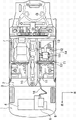
图2是拆下图1的车辆的左前座椅后的状态的俯视图。Fig. 2 is a plan view of a state in which the left front seat of the vehicle of Fig. 1 is removed.
图3是从上方观看图2的电池壳体的俯视图。Fig. 3 is a plan view of the battery case of Fig. 2 viewed from above.
图4是图3的B-B截面图。Fig. 4 is a B-B sectional view of Fig. 3 .
图5是图3的A-A截面图。Fig. 5 is an A-A sectional view of Fig. 3 .
图6是拆下图3的电池壳体的上壳体后的下壳体的左前方立体图。6 is a left front perspective view of the lower case with the upper case removed from the battery case of FIG. 3 .
图7是外力从车辆侧方作用的情况的说明图。Fig. 7 is an explanatory diagram of a case where an external force acts from the side of the vehicle.
附图标记说明Explanation of reference signs
1发动机室1 engine room
2车厢2 compartments
3前围板3 cowl
4发动机4 engines
5变速器5 transmissions
6电池6 batteries
7前座椅7 front seats
8后座椅8 rear seats
9地板面板9 floor panels
10通道10 channels
11前方支架11 front bracket
12后方支架12 rear bracket
13横梁13 beams
14下纵梁14 lower stringer
15电池壳体15 battery case
16第1电力电缆16 1st power cable
17第2电力电缆17 2nd power cable
18下壳体18 lower shell
19上壳体19 upper shell
20基座部20 base part
21纵壁部21 vertical wall
22顶板部22 top plate
23外壁部23 outer wall
24单格电池24 cells
25电池25 batteries
26固定部26 fixed part
27贯通孔27 through holes
28电池用支架28 battery bracket
29螺栓(紧固件)29 bolts (fasteners)
30凸缘部30 Flange
31纵梁31 stringer
具体实施方式Detailed ways
下面参照附图说明本实用新型的车辆用电池包的实施方式。图1是示出应用本实用新型的车辆用电池包的车辆的一实施方式的侧视图,图2是拆下图1的车辆的左前座椅后的状态的俯视图。本实施方式的车辆是在车辆前方具备发动机室1、在发动机室1的车辆后方具有车厢2的乘用汽车。发动机室1和车厢2由前围板3划分,在发动机室1内收纳有发动机4、变速器5、电池6等。另外,在车厢2内收纳有左右独立的前座椅7、左右连续的后座椅8等。Embodiments of the vehicle battery pack of the present invention will be described below with reference to the accompanying drawings. 1 is a side view showing an embodiment of a vehicle to which the vehicle battery pack of the present invention is applied, and FIG. 2 is a plan view of a state in which the left front seat of the vehicle in FIG. 1 is removed. The vehicle of the present embodiment is a passenger car including an engine room 1 at the front of the vehicle and a
车厢2内的底板由地板面板9构成(在本实施方式中,车厢2的车辆后方的行李箱的底板也连续地构成)。本实施方式的地板面板9的车辆宽度方向中央部(内侧)的上表面拱起而在车辆前后方向上形成有长条的通道10。该通道10收纳用于将例如车辆前方发动机室1内的发动机4的驱动力传送给后轮的传动轴。左右前座椅7装配于隔着该通道10的车辆的左右两侧。The floor in the
另外,地板面板9的车辆宽度方向两端部的上表面也向上方拱起而在车辆前后方向上形成有长条的下纵梁14。下纵梁14是在车辆宽度方向两端部的门开口部的下端部使地板面板9向车厢2内侧突出弯曲来提高门开口部的强度的部件。并且,在前座椅7的车辆前方端部的部分,设有连接通道10和下纵梁14的横梁13。例如,左前座椅7装配于前方支架11和后方支架12,前方支架11设于横梁13的下纵梁14侧端部上表面和横梁13的通道10侧端部上表面,后方支架12在比前方支架11靠近车辆后方处设于下纵梁14侧和通道10侧。In addition, the upper surfaces of both end portions in the vehicle width direction of the
在本实施方式中,在该左前座椅7下方的地板面板9的上表面,装配内装电池的电池壳体15。该电池壳体15内的电池用于在发动机4怠速停止时例如向仪表板提供电力,或者向配置在发动机室1内的辅机提供电力。因此,电池壳体15内的电池利用图中示出的第1电力电缆16连接到电池6,并且利用后述的第2电力电缆连接到仪表板。In the present embodiment, a
图3中示出从上方观看图2的电池壳体的俯视图,图4中示出图3的B-B截面图,图5中示出图3的A-A截面图,图6中示出拆下图3的电池壳体的上壳体后的下壳体的左前方立体图。图3中还示出了上述第2电力电缆17。另外,在图4中,可以看见配置在地板面板9的下侧的纵梁31。该电池壳体15分为下壳体18和上壳体19两者,下壳体18为壳体的基部,装配于地板面板9,上壳体19以覆盖下壳体18的上方的方式扣在该下壳体18上。Figure 3 shows a top view of the battery case of Figure 2 viewed from above, Figure 4 shows a B-B sectional view of Figure 3 , Figure 5 shows a A-A sectional view of Figure 3 , and Figure 6 shows a disassembled Figure 3 Left front perspective view of the lower case behind the upper case of the battery case. FIG. 3 also shows the above-mentioned
下壳体18具备大致方形的平板状的基座部20和从该方形平板状的基座部20的四边的侧缘部立起而构成内部空间的纵壁部21。另一方面,上壳体19具备覆盖上述纵壁部21的上部的大致方形的平板状的顶板部22和从该方形平板状的顶板部22的四边的侧缘部立起而紧密地覆盖上述纵壁部21的周围的外壁部23。因此,当用外壁部23包围纵壁部21的周围,在下壳体18的上方盖上上壳体19,用顶板部22覆盖纵壁部21的上部时,内部空间被密封。在该下壳体18和上壳体19的内部空间中,收纳有由多个单格电池24构成的电池25、未图示的控制部件等。在本实施方式中,将它们概括为电池。The
另一方面,在下壳体18,在总计5处形成有用于将电池壳体15固定于地板面板9的方形平板状的固定部26。这些固定部26均从方形平板状的基座部20的侧缘部中的位于车辆宽度方向两端部的侧缘部朝向车辆宽度方向两侧突出。其中,2处固定部26从下壳体18的基座部20朝向下纵梁14侧突出,3处固定部26从下壳体18的基座部20朝向通道10侧突出。朝向下纵梁14侧突出的2处固定部26分别从基座部20的下纵梁14侧的侧缘部的车辆前方端部和车辆后方端部(或者与它们相邻的部分)朝向下纵梁14侧突出。另外,朝向通道10侧突出的3处固定部26分别从基座部20的通道10侧的侧缘部的车辆前方端部、车辆后方端部(或者与它们相邻的部分)以及它们的中间部朝向通道10侧突出。在各固定部26的中央部,形成有用于插入作为紧固件的螺栓29的贯通孔27。On the other hand, in the
另外,在上述固定部26中的向下纵梁14侧突出的2处固定部26之间的基座部20的侧缘部,以将这些固定部26结合起来的方式突出形成有平板状的凸缘部30。该凸缘部30将向下纵梁14侧突出的2处固定部26间结合起来而提高整体强度,并且具有抑制特别是向下纵梁14侧突出的固定部26因后述的来自车辆侧方的外力而变形或者破损的功能。此外,下壳体18的基座部20、纵壁部21、固定部26、凸缘部30由例如铝的压铸(铸造)产品一体形成。一般地,铝的铸造产品比薄板的冲压成形品机械强度高。In addition, in the side edge portion of the
另一方面,在与上述下壳体18的固定部26相对的地板面板9处以向车厢2侧突出的方式设有电池用支架28。在这些电池用支架28中分别形成有未图示的螺纹孔。因此,下壳体18的固定部26搭载于电池用支架28的上部而将下壳体18配置在地板面板9上。并且,将作为紧固件的螺栓29插入各固定部26的贯通孔27中,且将这些螺栓29的阳螺纹拧紧到电池用支架28的螺纹孔中而将下壳体18固定于地板面板9。On the other hand, a
这样,相对于装配于地板面板9的电池壳体15,如图7所示,横梁13位于车辆前方,通道10位于车辆宽度方向内侧,下纵梁14位于车辆宽度方向外侧。该横梁13、通道10、下纵梁14均为强度构件,不易变形。例如,将正常时的下纵梁14的状态设为连结下纵梁14和横梁13的交点O与下纵梁14的车辆后方侧的点P的直线OP。当外力从车辆侧方作用时,下纵梁14本身不会从该状态很大地变形,主要是地板面板9变形,由此下纵梁14的比横梁13靠近车辆后方的一侧向车辆宽度方向内侧移位。例如,若将上述下纵梁14的比横梁13靠近车辆后方的一侧的点P的移动位置设为点Q,则当来自车辆侧方的外力作用时,下纵梁14会移位到图7的直线OQ的位置。Thus, with respect to the
针对由该来自车辆侧方的外力引起的下纵梁14向车辆宽度方向内侧的移位,在本实施方式中,包围内部空间的纵壁部21从构成电池壳体15的下壳体18的基座部20的侧缘部立起。因此,能够使向车辆宽度方向内侧移位的下纵梁14接触纵壁部21而保护空间内部的电池25。另外,由于有从基座部20向下纵梁14侧突出的固定部26和螺栓29,在接触纵壁部21之前,固定部26和螺栓29会接触向车辆宽度方向内侧移位的下纵梁14,能够保护电池壳体15和电池壳体15内的电池25。With respect to the displacement of the
另外,电池壳体15由配置于车辆宽度方向外侧的下纵梁14、配置于车辆宽度方向内侧的通道10、配置于车辆前方侧的横梁13包围。因此,在外力从车辆侧方作用的情况下,越是远离横梁13的下纵梁14的车辆后方侧,进入车辆宽度方向内侧的量越大。在这种情况下,向下纵梁14侧突出的固定部26中的车辆后方侧的固定部26和螺栓29会最先接触移位的下纵梁14,能够保护电池壳体15内的电池。In addition, the
另外,下壳体18的基座部20、纵壁部21以及固定部26通过铸造而一体化,因此即使冲击载荷作用于固定部26,固定部26在与纵壁部21的接合部、与基座部20的接合部处也不易变形、破损,能够保护电池壳体15内的电池25。另外,将向下纵梁14侧突出的固定部26连结到设于基座部20的侧缘部的凸缘部30。因此,利用凸缘部30提高了固定部26和基座部20的结合强度,在固定部26与下纵梁14接触的情况下,能够防止固定部26在与基座部20的接合部处破损而保护电池。In addition, since the
这样,在本实施方式的车辆用电池包中,将包围电池25的环状的纵壁部21设于下壳体,因此即使在外力从车辆侧方作用,下纵梁14被压入车辆宽度方向内侧的情况下,下纵梁14也会接触下壳体18的纵壁部21,能够保护电池壳体15内的电池25。另外,固定部26中的至少1个固定部形成在基座部20的与下纵梁14相对的侧缘部,并且突出于纵壁部21并朝向下纵梁14侧,因此在外力从车辆侧方作用,下纵梁14被压入车辆宽度方向内侧的情况下,向下纵梁14侧突出的固定部26和用于将该固定部26固定于地板面板9的螺栓29会比纵壁部21先接触下纵梁14,能够保护电池壳体15和电池壳体15内的电池25。因此,即使在外力从车辆侧方作用的情况下,也能够防止电池25和下纵梁14的接触,能够保护电池壳体15内的电池25。另外,不需要为了保护电池25而在电池壳体15的车辆前方侧和车辆后方侧两侧都配置横梁,实现车体结构的简化。In this way, in the vehicle battery pack according to the present embodiment, since the annular
另外,下纵梁14配置于比电池壳体15靠近车辆宽度方向外侧,通道10配置于比电池壳体15靠近车辆宽度方向内侧。并且,连接下纵梁14和通道10的横梁13配置于比电池壳体15靠近车辆前方。在这种情况下,如果外力从车辆侧方作用,则越是远离横梁13的下纵梁14的车辆后方侧,进入车辆宽度方向内侧的量越大。与此相对,将固定部26中的至少1个固定部配置于与下纵梁14相对的基座部20的侧缘部中的车辆后方侧的端部相邻的部分。因此,即使在外力从车辆侧方作用的情况下,与下纵梁14相对的基座部20的侧缘部的车辆后方端部的固定部26也会接触下纵梁14,能够保护电池壳体15内的电池25。另外,在电池壳体15的车辆后方侧不需要横梁,实现车体结构的简化。In addition, the
另外,下壳体18的基座部20、纵壁部21以及固定部26通过铸造而一体化,因此即使在冲击载荷作用于固定部26的情况下,也能够防止固定部26在与纵壁部21的接合部、与基座部20的接合部处变形或者破损,提高保护电池壳体15内的电池25的效果。In addition, since the
另外,在利用凸缘部30提高固定部26和基座部20的结合强度,固定部26与下纵梁14接触的情况下,能够防止固定部26在与基座部20的接合部处破损而提高保护电池25的效果。In addition, when the bonding strength between the fixing
Claims (4)
Applications Claiming Priority (2)
| Application Number | Priority Date | Filing Date | Title |
|---|---|---|---|
| JP2012163788A JP2014024359A (en) | 2012-07-24 | 2012-07-24 | Vehicular battery pack |
| JP2012-163788 | 2012-07-24 |
Publications (1)
| Publication Number | Publication Date |
|---|---|
| CN203358315U true CN203358315U (en) | 2013-12-25 |
Family
ID=49806129
Family Applications (1)
| Application Number | Title | Priority Date | Filing Date |
|---|---|---|---|
| CN201320406610.2U Expired - Fee Related CN203358315U (en) | 2012-07-24 | 2013-07-09 | Battery pack used for vehicle |
Country Status (2)
| Country | Link |
|---|---|
| JP (1) | JP2014024359A (en) |
| CN (1) | CN203358315U (en) |
Cited By (8)
| Publication number | Priority date | Publication date | Assignee | Title |
|---|---|---|---|---|
| CN104401403A (en) * | 2014-10-28 | 2015-03-11 | 长城汽车股份有限公司 | Floor component applied to vehicle and vehicle |
| CN106240330A (en) * | 2015-06-05 | 2016-12-21 | 铃木株式会社 | The mounting structure of vehicle battery bag |
| CN106364298A (en) * | 2015-07-23 | 2017-02-01 | 铃木株式会社 | Vehicle battery pack |
| CN107054038A (en) * | 2016-01-27 | 2017-08-18 | 株式会社丰田自动织机 | Vehicle |
| CN110040179A (en) * | 2018-01-16 | 2019-07-23 | 铃木株式会社 | The body construction of electric vehicle |
| CN110194053A (en) * | 2018-02-23 | 2019-09-03 | 丰田自动车株式会社 | Lower vehicle construction |
| CN110239625A (en) * | 2018-03-08 | 2019-09-17 | 铃木株式会社 | The fixture construction of electric device |
| CN113799882A (en) * | 2020-06-15 | 2021-12-17 | 现代自动车株式会社 | Vehicle floor structure |
Families Citing this family (12)
| Publication number | Priority date | Publication date | Assignee | Title |
|---|---|---|---|---|
| JP6747275B2 (en) | 2016-12-14 | 2020-08-26 | 株式会社デンソー | Battery pack |
| CN109204543B (en) * | 2017-06-30 | 2020-11-06 | 比亚迪股份有限公司 | Vehicle body structure and vehicle |
| JP7196444B2 (en) * | 2018-07-18 | 2022-12-27 | スズキ株式会社 | Vehicle power supply fixing structure |
| JP7323033B2 (en) * | 2018-07-18 | 2023-08-08 | スズキ株式会社 | Vehicle power supply fixing structure |
| JP7327626B2 (en) * | 2018-07-18 | 2023-08-16 | スズキ株式会社 | Vehicle power supply fixing structure |
| JP7151231B2 (en) * | 2018-07-18 | 2022-10-12 | スズキ株式会社 | Vehicle power supply fixing structure |
| WO2020044792A1 (en) * | 2018-08-28 | 2020-03-05 | 本田技研工業株式会社 | Battery pack arrangement structure |
| JP7322558B2 (en) * | 2019-07-10 | 2023-08-08 | 株式会社デンソー | vehicle battery pack |
| JP7331593B2 (en) * | 2019-09-30 | 2023-08-23 | スズキ株式会社 | Electrical component support structure |
| JP7272222B2 (en) * | 2019-09-30 | 2023-05-12 | スズキ株式会社 | Electrical component support structure |
| CN114506200B (en) * | 2020-10-29 | 2023-12-22 | 本田技研工业(中国)投资有限公司 | Battery protection device and vehicle with same |
| JP7240434B2 (en) | 2021-03-30 | 2023-03-15 | 本田技研工業株式会社 | electric vehicle |
Family Cites Families (3)
| Publication number | Priority date | Publication date | Assignee | Title |
|---|---|---|---|---|
| DE112004002247B8 (en) * | 2003-11-28 | 2014-04-03 | Toyota Jidosha Kabushiki Kaisha | Fixing structure for a vehicle battery pack |
| JP4806924B2 (en) * | 2004-11-12 | 2011-11-02 | 株式会社Gsユアサ | Assembled battery |
| JP2008260465A (en) * | 2007-04-13 | 2008-10-30 | Toyota Motor Corp | Electrical equipment mounting structure |
-
2012
- 2012-07-24 JP JP2012163788A patent/JP2014024359A/en active Pending
-
2013
- 2013-07-09 CN CN201320406610.2U patent/CN203358315U/en not_active Expired - Fee Related
Cited By (12)
| Publication number | Priority date | Publication date | Assignee | Title |
|---|---|---|---|---|
| CN104401403A (en) * | 2014-10-28 | 2015-03-11 | 长城汽车股份有限公司 | Floor component applied to vehicle and vehicle |
| CN106240330A (en) * | 2015-06-05 | 2016-12-21 | 铃木株式会社 | The mounting structure of vehicle battery bag |
| CN106240330B (en) * | 2015-06-05 | 2019-08-02 | 铃木株式会社 | The mounting structure of vehicle battery packet |
| CN106364298A (en) * | 2015-07-23 | 2017-02-01 | 铃木株式会社 | Vehicle battery pack |
| CN107054038A (en) * | 2016-01-27 | 2017-08-18 | 株式会社丰田自动织机 | Vehicle |
| CN107054038B (en) * | 2016-01-27 | 2019-06-18 | 株式会社丰田自动织机 | vehicle |
| CN110040179A (en) * | 2018-01-16 | 2019-07-23 | 铃木株式会社 | The body construction of electric vehicle |
| CN110194053A (en) * | 2018-02-23 | 2019-09-03 | 丰田自动车株式会社 | Lower vehicle construction |
| CN110194053B (en) * | 2018-02-23 | 2022-03-08 | 丰田自动车株式会社 | Vehicle lower structure |
| CN110239625A (en) * | 2018-03-08 | 2019-09-17 | 铃木株式会社 | The fixture construction of electric device |
| CN113799882A (en) * | 2020-06-15 | 2021-12-17 | 现代自动车株式会社 | Vehicle floor structure |
| CN113799882B (en) * | 2020-06-15 | 2024-05-10 | 现代自动车株式会社 | Vehicle floor structure |
Also Published As
| Publication number | Publication date |
|---|---|
| JP2014024359A (en) | 2014-02-06 |
Similar Documents
| Publication | Publication Date | Title |
|---|---|---|
| CN203358315U (en) | Battery pack used for vehicle | |
| US10464406B2 (en) | Vehicle body bottom structure | |
| CN110588312B (en) | Vehicle body lower structure | |
| US11208152B2 (en) | Vehicle body side section structure | |
| CN211731599U (en) | Body floor assembly and its battery pack, vehicle | |
| US10486746B2 (en) | Substructure of vehicle body | |
| JP6520424B2 (en) | Vehicle battery pack mounting structure | |
| CN109263455B (en) | front body structure | |
| US10150435B2 (en) | Vehicle lower portion structure | |
| KR102474370B1 (en) | Side vehicle body reinforcing structure | |
| CN110239628B (en) | Vehicle rear structure | |
| US10826032B2 (en) | Battery pack | |
| US8776927B2 (en) | Vehicle battery pack housing structure | |
| JP2025096508A (en) | Battery mounting structure for vehicle | |
| US10978760B2 (en) | Structural component, battery housing, and motor vehicle with such a battery housing | |
| CN112739611B (en) | Vehicle body lower structure | |
| JP5472361B2 (en) | Vehicle battery mounting structure | |
| CN110077469B (en) | body structure | |
| US9576701B2 (en) | High-voltage wire wiring structure in vehicle | |
| JP2011168242A (en) | Installation structure of battery unit for vehicle | |
| CN109318994B (en) | vehicle front structure | |
| JP2018203029A (en) | Lower body structure | |
| US12304295B2 (en) | Energy store floor assembly | |
| US20160233467A1 (en) | Impact Absorbing Elements Attached to the Outer Surface of a Battery Enclosure | |
| JP2013147137A (en) | Floor structure of electrically driven vehicle |
Legal Events
| Date | Code | Title | Description |
|---|---|---|---|
| C14 | Grant of patent or utility model | ||
| GR01 | Patent grant | ||
| CF01 | Termination of patent right due to non-payment of annual fee | ||
| CF01 | Termination of patent right due to non-payment of annual fee |
Granted publication date: 20131225 Termination date: 20200709 |