CN203288866U - Electric coupler and combination thereof - Google Patents
Electric coupler and combination thereof Download PDFInfo
- Publication number
- CN203288866U CN203288866U CN2013201873720U CN201320187372U CN203288866U CN 203288866 U CN203288866 U CN 203288866U CN 2013201873720 U CN2013201873720 U CN 2013201873720U CN 201320187372 U CN201320187372 U CN 201320187372U CN 203288866 U CN203288866 U CN 203288866U
- Authority
- CN
- China
- Prior art keywords
- connector
- guide
- guide posts
- docking
- along
- Prior art date
- Legal status (The legal status is an assumption and is not a legal conclusion. Google has not performed a legal analysis and makes no representation as to the accuracy of the status listed.)
- Expired - Lifetime
Links
Images


Classifications
-
- H—ELECTRICITY
- H01—ELECTRIC ELEMENTS
- H01R—ELECTRICALLY-CONDUCTIVE CONNECTIONS; STRUCTURAL ASSOCIATIONS OF A PLURALITY OF MUTUALLY-INSULATED ELECTRICAL CONNECTING ELEMENTS; COUPLING DEVICES; CURRENT COLLECTORS
- H01R12/00—Structural associations of a plurality of mutually-insulated electrical connecting elements, specially adapted for printed circuits, e.g. printed circuit boards [PCB], flat or ribbon cables, or like generally planar structures, e.g. terminal strips, terminal blocks; Coupling devices specially adapted for printed circuits, flat or ribbon cables, or like generally planar structures; Terminals specially adapted for contact with, or insertion into, printed circuits, flat or ribbon cables, or like generally planar structures
- H01R12/70—Coupling devices
- H01R12/71—Coupling devices for rigid printing circuits or like structures
- H01R12/72—Coupling devices for rigid printing circuits or like structures coupling with the edge of the rigid printed circuits or like structures
- H01R12/73—Coupling devices for rigid printing circuits or like structures coupling with the edge of the rigid printed circuits or like structures connecting to other rigid printed circuits or like structures
- H01R12/732—Printed circuits being in the same plane
-
- H—ELECTRICITY
- H01—ELECTRIC ELEMENTS
- H01R—ELECTRICALLY-CONDUCTIVE CONNECTIONS; STRUCTURAL ASSOCIATIONS OF A PLURALITY OF MUTUALLY-INSULATED ELECTRICAL CONNECTING ELEMENTS; COUPLING DEVICES; CURRENT COLLECTORS
- H01R13/00—Details of coupling devices of the kinds covered by groups H01R12/70 or H01R24/00 - H01R33/00
- H01R13/62—Means for facilitating engagement or disengagement of coupling parts or for holding them in engagement
- H01R13/629—Additional means for facilitating engagement or disengagement of coupling parts, e.g. aligning or guiding means, levers, gas pressure electrical locking indicators, manufacturing tolerances
-
- H—ELECTRICITY
- H01—ELECTRIC ELEMENTS
- H01R—ELECTRICALLY-CONDUCTIVE CONNECTIONS; STRUCTURAL ASSOCIATIONS OF A PLURALITY OF MUTUALLY-INSULATED ELECTRICAL CONNECTING ELEMENTS; COUPLING DEVICES; CURRENT COLLECTORS
- H01R13/00—Details of coupling devices of the kinds covered by groups H01R12/70 or H01R24/00 - H01R33/00
- H01R13/648—Protective earth or shield arrangements on coupling devices, e.g. anti-static shielding
- H01R13/658—High frequency shielding arrangements, e.g. against EMI [Electro-Magnetic Interference] or EMP [Electro-Magnetic Pulse]
- H01R13/6581—Shield structure
-
- H—ELECTRICITY
- H01—ELECTRIC ELEMENTS
- H01R—ELECTRICALLY-CONDUCTIVE CONNECTIONS; STRUCTURAL ASSOCIATIONS OF A PLURALITY OF MUTUALLY-INSULATED ELECTRICAL CONNECTING ELEMENTS; COUPLING DEVICES; CURRENT COLLECTORS
- H01R27/00—Coupling parts adapted for co-operation with two or more dissimilar counterparts
- H01R27/02—Coupling parts adapted for co-operation with two or more dissimilar counterparts for simultaneous co-operation with two or more dissimilar counterparts
Landscapes
- Details Of Connecting Devices For Male And Female Coupling (AREA)
Abstract
本实用新型公开了一种电连接器及其组合,电连接器包括具有第一方向及第二方向的绝缘本体、沿第二方向排列的导电端子及遮蔽壳体;所述绝缘本体包括基部、沿第一方向延伸的对接部及一对导引柱,对接部设有垂直于第一、第二方向的对接面,该对导引柱分别位于对接部的两侧且沿第一方向较对接面凸出,导引柱至少具有平行于第一、第二方向的两个相对的侧面及一个外端面;导引柱的上述两个侧面及外端面之其中之一设有第一导引缝,第一导引缝呈U型并沿第一方向贯穿导引柱的自由末端。本实用新型的第一导引槽有利于跟第一导引片配合,有利于两连接器对接时的导引作用。
The utility model discloses an electrical connector and a combination thereof. The electrical connector includes an insulating body having a first direction and a second direction, conductive terminals arranged along the second direction, and a shielding case; the insulating body includes a base, A docking portion extending along the first direction and a pair of guiding columns, the docking portion is provided with a docking surface perpendicular to the first and second directions, the pair of guiding columns are respectively located on both sides of the docking portion and relatively docked along the first direction The surface is convex, and the guide column has at least two opposite side surfaces parallel to the first and second directions and an outer end surface; one of the above two side surfaces and the outer end surface of the guide column is provided with a first guide slot , the first guiding slit is U-shaped and runs through the free end of the guiding column along the first direction. The first guide groove of the utility model is beneficial to cooperate with the first guide piece, and is beneficial to the guiding function when the two connectors are docked.
Description
【技术领域】【Technical field】
本实用新型涉及一种电连接器及其组合,尤其涉及一种具有组合接口的电连接器及其组合。 The utility model relates to an electric connector and a combination thereof, in particular to an electric connector with a combination interface and the combination thereof.
【背景技术】【Background technique】
随着电子设备轻、薄、短、小的发展,电子设备的内部空间会越来越狭小,因此,通过在有限的空间内设置多个不同的电连接器来实现电子设备的各种不同功能,已不再符合电子设备的发展需求,需要设计一种新的占用电子设备较小的内部空间且能满足多种功能需求的电连接器。 With the development of light, thin, short and small electronic equipment, the internal space of electronic equipment will become smaller and smaller. Therefore, various functions of electronic equipment can be realized by setting multiple different electrical connectors in a limited space , no longer meet the development needs of electronic equipment, and it is necessary to design a new electrical connector that occupies a small internal space of electronic equipment and can meet multiple functional requirements.
美国专利公告第7,946,887号揭示了一种具有组合接口的电连接器组件,该电连接器组件包括相互配接的第一连接器与第二连接器。其中第一连接器包括纵长的本体及固持于本体的第一端子组与第二端子组,本体包括并列设置的第一对接腔与第二对接腔,第一对接腔内设有第一舌板,第一舌板与第二对接腔间隔设置,第一端子组排列于第一舌板的同一表面,第二端子组设置于第二对接腔内。该第一连接器具有组合接口,占用电子设备的内部空间较小且能满足多种功能需求。然而,第一舌板与第二对接腔间隔设置,二者之间具有较大的缝隙,纵长的本体容易在该缝隙处发生断裂;而随着传输速度的提高,端子逐渐增多,将端子排设于单一舌板上容易使信号之间的串扰愈发严重。同时,导引功能亦不够强。 US Patent No. 7,946,887 discloses an electrical connector assembly with a combination interface, the electrical connector assembly includes a first connector and a second connector mated with each other. Wherein the first connector includes a lengthwise body and a first terminal group and a second terminal group held in the body, the body includes a first docking cavity and a second docking cavity arranged side by side, and a first tongue is arranged in the first docking cavity plate, the first tongue plate and the second docking cavity are arranged at intervals, the first terminal group is arranged on the same surface of the first tongue plate, and the second terminal group is arranged in the second docking cavity. The first connector has a combined interface, occupies less internal space of the electronic device and can meet various functional requirements. However, the first tongue plate and the second docking cavity are arranged at intervals, and there is a large gap between them, and the longitudinal body is easy to break at the gap; and as the transmission speed increases, the number of terminals gradually increases, and the terminals Arranging on a single tongue plate tends to make the crosstalk between signals more serious. At the same time, the guidance function is not strong enough.
因此,鉴于前述电连接器组件的不足,有必要设计一种新的电连接器用来解决上述问题。 Therefore, in view of the shortcomings of the aforementioned electrical connector assembly, it is necessary to design a new electrical connector to solve the above problems.
【实用新型内容】【Content of utility model】
本实用新型所要解决的技术方案是提供一种电连接器及其组合,有利于对接时的导引作用。 The technical solution to be solved by the utility model is to provide an electric connector and its combination, which is beneficial to the guiding function during docking.
本实用新型的目的是通过以下技术方案实现的:一种电连接器,其包括具有第一方向及第二方向的绝缘本体、沿第二方向排列的导电端子及遮蔽壳体;所述绝缘本体包括基部、沿第一方向延伸的对接部及一对导引柱,对接部设有垂直于第一、第二方向的对接面,该对导引柱分别位于对接部的两侧且沿第一方向较对接面凸出,导引柱至少具有平行于第一、第二方向的两个相对的侧面及一个外端面;导引柱的上述两个侧面及外端面之其中之一设有第一导引缝,第一导引缝呈U型并沿第一方向贯穿导引柱的自由末端。 The purpose of this utility model is achieved through the following technical solutions: an electrical connector, which includes an insulating body with a first direction and a second direction, conductive terminals arranged along the second direction, and a shielding case; the insulating body It includes a base, a butt joint extending along the first direction and a pair of guide columns, the butt joint is provided with a joint surface perpendicular to the first and second directions, and the pair of guide posts are respectively located on both sides of the butt joint and along the first The direction is more protruding than the docking surface, and the guide column has at least two opposite side surfaces and an outer end surface parallel to the first and second directions; one of the above two side surfaces and the outer end surface of the guide column is provided with a first The guiding seam, the first guiding seam is U-shaped and runs through the free end of the guiding column along the first direction.
本实用新型的目的是通过以下另一技术方案实现的:一种电连接器组合,其包括沿第一方向配接的第一连接器及第二连接器,第一、第二连接器分别具有绝缘本体、导电端子及遮蔽壳体;第一连接器的遮蔽壳体包围绝缘本体而形成对接空间,遮蔽壳体具有相对的第一侧壁与第二侧壁,第一侧壁的对接缘处弯折有向第二侧壁延伸的第一导引片,第二侧壁撕裂有延伸入对接空间的第二导引片,第二导引片沿第一方向延伸,第一导引片垂直于第一方向;第一连接器的绝缘本体设有对接部及位于对接部两端的导引柱;上述第二连接器的两个导引柱分别设有沿第一方向延伸的第一导引槽及第二导引槽,前述第一、第二导引槽供对接连接器的第一、第二导引片插入。 The purpose of this utility model is achieved through the following another technical solution: an electrical connector combination, which includes a first connector and a second connector mated along the first direction, the first and second connectors have respectively The insulating body, the conductive terminal and the shielding shell; the shielding shell of the first connector surrounds the insulating body to form a docking space, the shielding shell has opposite first side walls and second side walls, and the butt joint edge of the first side wall A first guide piece extending toward the second side wall is bent, a second guide piece extending into the docking space is torn from the second side wall, the second guide piece extends along the first direction, and the first guide piece perpendicular to the first direction; the insulating body of the first connector is provided with a docking portion and guide posts located at both ends of the docking portion; the two guide posts of the second connector are respectively provided with first guide posts extending along the first direction A guide groove and a second guide groove, the aforementioned first and second guide grooves are used for inserting the first and second guide pieces of the docking connector.
相较于现有技术,本实用新型的第一导引槽有利于跟第一导引片配合,有利于两连接器对接时的导引作用。 Compared with the prior art, the first guide groove of the present invention is beneficial to cooperate with the first guide piece, and is beneficial to the guiding function when the two connectors are docked.
【附图说明】【Description of drawings】
图1为本实用新型电连接器组合相配接后的立体图。 Fig. 1 is a perspective view of the electric connector of the present invention after being combined and mated.
图2为本实用新型电连接器组合的局部放大图。 Fig. 2 is a partially enlarged view of the electrical connector combination of the present invention.
图3为图1所示本实用新型第一连接器的分解图。 FIG. 3 is an exploded view of the first connector of the present invention shown in FIG. 1 .
图4为图3所示另一角度的视图。 FIG. 4 is a view from another angle shown in FIG. 3 .
图5为图1所示本实用新型第一连接器的正视图。 Fig. 5 is a front view of the first connector of the present invention shown in Fig. 1 .
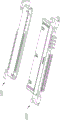
图6为图1所示本实用新型第二连接器的分解图。 FIG. 6 is an exploded view of the second connector of the present invention shown in FIG. 1 .
图7为图6所示另一角度的视图。 FIG. 7 is a view from another angle shown in FIG. 6 .
图8为图1所示本实用新型第二连接器的正视图。 Fig. 8 is a front view of the second connector of the present invention shown in Fig. 1 .
图9为沿图1所示A-A线的剖视图。 Fig. 9 is a sectional view along line A-A shown in Fig. 1 .
图10为沿图1所示B-B线的剖视图。 Fig. 10 is a sectional view along line B-B shown in Fig. 1 .
图11为本实用新型电连接器组合另一实施例的立体图。 FIG. 11 is a perspective view of another embodiment of the electrical connector combination of the present invention.
【具体实施方式】【Detailed ways】
请参图1及图2所示,本实用新型揭示了一种电连接器组合,其包括沿第一方向(即对接方向)相互配接的第一连接器100与第二连接器200,两个连接器分别安装在两块电路板1002、1001上。第一、第二连接器分别包括具有第一方向及第二方向的绝缘本体、沿第二方向排列的导电端子及金属制成的遮蔽壳体。具体细节下面介绍,其中,下文提及的第一、第二的定义,并无先后顺序,仅用以表明不同的元件。
Please refer to Figure 1 and Figure 2, the utility model discloses an electrical connector combination, which includes a
请参图3至图5所示,第一连接器100包括由绝缘材料制成的绝缘本体1、固持于绝缘本体1的端子21、22、组装绝缘本体的定位板3、遮覆于绝缘本体1的遮蔽壳体4及设置于遮蔽壳体4外的金属固定件5。
3 to 5, the
绝缘本体1包括纵长的基部10、自基部10沿第一方向延伸的对接部及自基部10的两端分别沿第二方向(即纵长方向)向外延伸的一对安装部15。对接部包括第一舌板11与第二舌板12、自基部10向前突伸的一对隔板。第一舌板11与第二舌板12自基部10向前延伸且彼此相对平行设置,第一舌板11与第二舌板12间隔一定距离,第一舌板11具有第一对接面111,第二舌板12设有与第一对接面111相对设置的第二对接面121,即第一、第二对接面111、121位于两个舌板的内侧且彼此面对面设置。两隔板分为间隔设置的第一隔板13与第二隔板14,第一隔板13连接第一舌板11的一端与第二舌板12的一端,在本实施方式中,第一隔板13与第一舌板11及第二舌板12一体成型。第二隔板14自基部10向前延伸。第一舌板11、第二舌板12、第一隔板13及第二隔板14均自基部10的前端面101延伸,安装部15自基部10的后端面延伸,安装部15具有面向前方的抵接面151及自抵接面151向后凹陷的浅凹部152,该抵接面151位于前端面101的后方。
The insulating body 1 includes a
端子包括若干第一端子21及若干第二端子22,第一端子21包括第一固持部210、自第一固持部210向前延伸的平板状第一接触部211、自第一固持部210后端向下弯折的延伸部212及平板状的第一焊接部213。第一端子21沿纵长方向设置于绝缘本体1,第一接触部211呈两排设置且分别位于第一对接面111与第二对接面121上,第一对接面111上的第一接触部211与第二对接面111上的第一接触部211在第二方向上形成错位(图5清楚显示),第一焊接部213延伸出第一本体1外且排列于同一排,延伸部212排列为前后两排。第二端子22为针状,其沿第二方向排列于绝缘本体1上,第二端子22的第二接触部221突设于第一隔板13与第二隔板14之间。第二端子22的焊接部延伸出绝缘本体本体1外。
The terminal includes a number of
定位板3包括主体部31及自主体部31的两侧分别向前延伸的扣臂32,主体部31的内表面凸设有间隔排列的隔栏311。定位板3组装于基部10的后部并通过扣臂32扣持于基部10而对应位于第一、第二舌板11、12的后方,位于后排的延伸部212分别位于相邻的隔栏311之间。定位板3的设置不仅可防止第一端子21自绝缘本体1的后方脱离,还可防止延伸部212之间的信号干扰。
The
遮蔽壳体4包括相对设置的第一侧壁41、第二侧壁42,以及分别连接于第一、第二侧壁41、42两端的两端壁43,上述四壁形成对接空间109内,参图5。结合图2,第一侧壁41在其两端邻近端壁43处的对接缘处弯折有向第二侧壁42延伸的第一导引片411,第一导引片垂直于第一方向。第二侧壁42则对应撕裂有弯折延伸入对接空间的第二导引片421。第一导引片411与第二导引片412在第二方向上形成错位,第一导引片411比第二导引片412更靠近对应端壁43。第一导引片411垂直于第一方向延伸,第二导引片412则沿第一方向延伸。遮蔽壳体4遮覆于第一本体1的外侧,并通过自两端壁43分别向后延伸的扣部431扣持对应的安装部15而固定于第一本体1。
The
固定件5包括平板部51及自平板部51两端向下弯折延伸的焊脚52,焊脚52上设有让位孔521。固定件5组装于遮蔽壳体4并被两端壁43上分别设置的弹性夹持部432所夹持,平板部51贴覆于第二侧壁41,焊脚52位于端壁43的外侧,端壁43上延伸的焊脚部430位于让位孔521内。该固定件5可使电连接器100稳固地固定于电路板1001上。
The fixing
遮蔽壳体4组装于绝缘本体本体1后,基部10、第一舌板11、第二舌板12、第一隔板13、第二隔板14及安装部15均位于遮蔽壳体4所围成的对接空间109内,参图5。第一舌板11及第二舌板12形成该第一连接器100的第一对接部102,第一隔板13与第二隔板14围设形成第二对接部103,该第二对接部103在第一隔板13与第二隔板14之间形成对接腔,第二端子22的第二接触部221突设于该对接腔内。第一对接部102与第二对接部103并列设置,该第一隔板13连接第一舌板11及第二舌板12,使得第一对接部102与第二对接部103相连接,从而可增加第一连接器100的强度。第一端子21的第一接触部211分别设置于两舌板相对设置的第一对接面111与第二对接面121,可增加第一端子21之间的间距,从而有利于改善第一端子21间的信号干扰。该遮蔽壳体4套设于绝缘本体1后,第一连接器100的两端于安装部15的前方分别形成导引穴105,第一导引片411与第二导引片412分别凸伸入该导引穴105。
After the shielding
请参图6至图8所示,第二连接器200包括绝缘本体6、固持于绝缘本体6的端子及组装于绝缘本体6的遮蔽壳体8。
Referring to FIGS. 6 to 8 , the
绝缘本体6包括基部61及沿第一方向(即对接方向)延伸的对接部69与一对导引柱64,对接部69设有垂直于第一、第二方向的对接面690,该对导引柱64分别位于对接部69的两侧且沿第二方向较对接面凸出。导引柱64与对接部62连接于一体,如此,每一导引柱64至少具有平行于第一、第二方向的两个相对的侧面645、646及一个外端面647,导引柱在垂直于两个侧面方向上的尺寸大于对接部。该尺寸较大的导引柱64与第一连接器的的导引穴15互相配合,能够在不增加整个连接器尺寸的情况下,较好的起到导引作用。对接部69包括沿第二方向平行排列的第一对接舌板62与第二对接舌板63。第一对接舌板62与第二对接舌板63间隔设置且二者之间形成第一收容部65,邻近第一对接舌板621设置的导引柱64与第一对接舌板62一体成型,第二对接舌板63则未直接连接与对应的导引柱64,第二对接舌板旁侧设有第二收容部66。第一对接舌板62的相对设置的两纵长表面上设有收容槽,第二对接舌板63内凹设有收容孔631。每一导引柱64于相对的两侧面645、646分别设置有第一导引槽641与第二导引槽642,第一导引槽641与第二导引槽642沿第一方向(即对接方向)延伸且贯穿导引柱的自由末端,且第一导引槽641与第二导引槽642在第二方向(即纵长方向)上错位设置。在最佳实施例中,第二导引槽642设置在导引柱64与对接部69交接处。当然,在其他实施例中,上述第一导引槽641可以设置在其他侧面或端面上。综上,导引柱的两个侧面及外端面之其中之一设有第一导引槽641,第一导引槽641沿第一方向贯穿导引柱的自由末端或对接部的对接缘,第一导引槽641呈U型,亦即该第一导引槽641在第一方向上贯穿,但在第二方向上没有贯穿导引槽641的外端面,该U型结构有助第一连接器的第一导引片的准确对准。
The insulating
端子包括第一端子71及第二端子72,第一端子71包括平板状的第一定位部711、自第一定位部711前端延伸的具有弹性的接触臂712及自第一定位部711的后端延伸的第一焊接端713。第二端子72包括柱状的第二定位部721、自第二定位部721的前端延伸的夹持部722及自第二定位部721的后端延伸的第二焊接端723。第一端子71通过第一定位部711固定于第二基部61且排列为两排,接触臂712分别暴露于第一对接舌板62的两纵长表面上设置的收容槽,第一焊接端713延伸出绝缘本体6且排列成两排。第二端子72通过第二定位部721固定于第二基部61,夹持部722收容于第二对接舌板63的收容孔631内,第二焊接端723延伸出绝缘本体6且排列成一排。
The terminals include a
遮蔽壳体8包括两个贴覆在对接部的第一侧壁81与第二侧壁82及连接于第一侧壁81与第二侧壁82的前端两侧的连接臂83。第一侧壁81及第二侧壁82分别贴覆在对接部的两侧。遮蔽壳体还设有向基部61方向弯折的固持脚84a、84b,固持脚沿第一、第二导引槽641、642移动而固定在基部61内。固持脚84a、84b在第二方向上错位设置。连接臂83抵靠在对接面690且邻接导引柱64,对接面在对应连接臂处设有贯穿对接面的孔洞691,该孔洞有助于绝缘本体的成型。导引柱64位于对接面前端的部分呈渐缩的锥形状。遮蔽壳体8向后组装于绝缘本体6,固持脚84a、84b分别沿第一导引槽641及第二导引槽642滑动以导引遮蔽壳体8顺畅地组装,直到固持脚84a、84b扣持于基部61以使遮蔽壳体8定位于绝缘本体6,第一侧壁81及第二侧壁82上设置的扣孔85扣持基部61上的扣块611以进一步加强遮蔽壳体8与绝缘本体6的固定。
The shielding
下面再介绍下第一、第二连接器互相对接的情况。请继续参阅图2、图9及图10所示,第一连接器100与第二连接器200相配接时,第一连接器100的第一导引片411及第二导引部412分别对应收容于第一导引槽641及第二导引槽642并沿第一方向(即对接方向)导引滑动,同时,第一对接舌板62延伸入第一舌板11与第二舌板12之间以使位于第一对接面111及第二对接面112的第一端子21与第一对接舌板62上的第一端子71达成电性连接,即使得第一对接舌板62与第一对接部102达成对接。第二对接舌板63延伸入对接腔104中,并使第二接触部221突伸入对接孔631以夹持于夹持部722,即使得第二对接舌板63与第二对接部103达成对接,第一隔板13及第二隔板14分别对应收容于第一收容部65与第二收容部66。导引柱64则收容于导引穴105中,且导引柱64的自由端部分突伸入浅凹部152。本实用新型电连接器及其组合具有组合接口,有利于改善高频性能,且能保证强度。从图2清楚可见,在第二方向上,第一导引411片的尺寸等于第一导引槽641,第一导引槽内设有第一连接器的第一导引片向第二连接器过度移动的阻挡面6411;从图11清楚可见,第二导引片的尺寸小于第二导引槽。
Next, the situation that the first and second connectors are connected to each other will be introduced. Please continue to refer to Fig. 2, Fig. 9 and Fig. 10, when the
为方便权利要求的界定,将上述第二连接器称为电连接器,第一连接器称为对接连接器。当然,权利要求不仅限于该实施例及名词定义。本实施方式为本实用新型较佳实施方式,当然,本实用新型也可采用其他实时方式,如图11显示的另一实施例,该电连接器组合包括第一连接器100’及第二连接器200’,此处不再一一赘述。 To facilitate the definition of the claims, the above-mentioned second connector is called an electrical connector, and the first connector is called a butt connector. Of course, the claims are not limited to the examples and definitions. This implementation mode is a preferred implementation mode of the utility model, of course, the utility model can also adopt other real-time methods, as shown in another embodiment shown in Figure 11, the electrical connector combination includes a first connector 100' and a second connection device 200', which will not be described in detail here.
Claims (10)
Priority Applications (3)
| Application Number | Priority Date | Filing Date | Title |
|---|---|---|---|
| CN2013201873720U CN203288866U (en) | 2013-04-15 | 2013-04-15 | Electric coupler and combination thereof |
| TW103202824U TWM496878U (en) | 2013-04-15 | 2014-02-19 | Electrical connector and electrical connector assembly |
| US14/252,797 US9300065B2 (en) | 2013-04-15 | 2014-04-15 | Electrical connector assembly having combination interface |
Applications Claiming Priority (1)
| Application Number | Priority Date | Filing Date | Title |
|---|---|---|---|
| CN2013201873720U CN203288866U (en) | 2013-04-15 | 2013-04-15 | Electric coupler and combination thereof |
Publications (1)
| Publication Number | Publication Date |
|---|---|
| CN203288866U true CN203288866U (en) | 2013-11-13 |
Family
ID=49545212
Family Applications (1)
| Application Number | Title | Priority Date | Filing Date |
|---|---|---|---|
| CN2013201873720U Expired - Lifetime CN203288866U (en) | 2013-04-15 | 2013-04-15 | Electric coupler and combination thereof |
Country Status (3)
| Country | Link |
|---|---|
| US (1) | US9300065B2 (en) |
| CN (1) | CN203288866U (en) |
| TW (1) | TWM496878U (en) |
Families Citing this family (3)
| Publication number | Priority date | Publication date | Assignee | Title |
|---|---|---|---|---|
| US10680363B2 (en) * | 2018-05-31 | 2020-06-09 | Te Connectivity Corporation | Card edge connector assembly |
| TWI700868B (en) * | 2019-07-22 | 2020-08-01 | 貿聯國際股份有限公司 | Oblique insertion prevention structure and interface card with oblique insertion prevention structure |
| CN118970538B (en) * | 2024-10-14 | 2025-03-18 | 广东鸿儒技术有限公司 | A dual-purpose, detachable connector structure for new energy vehicles |
Family Cites Families (27)
| Publication number | Priority date | Publication date | Assignee | Title |
|---|---|---|---|---|
| TW515583U (en) * | 2001-12-26 | 2002-12-21 | Hon Hai Prec Ind Co Ltd | Electrical connector |
| US6932646B2 (en) * | 2003-04-04 | 2005-08-23 | North Star Systems Corp. | Electrical connector assembly structure |
| TWM300879U (en) * | 2005-12-26 | 2006-11-11 | Hon Hai Prec Ind Co Ltd | Electrical connector |
| CN2932742Y (en) * | 2006-06-30 | 2007-08-08 | 富士康(昆山)电脑接插件有限公司 | holding device |
| CN2932676Y (en) * | 2006-07-03 | 2007-08-08 | 富士康(昆山)电脑接插件有限公司 | electrical connector |
| US7192297B1 (en) * | 2006-07-05 | 2007-03-20 | Hon Hai Precision Ind. Co., Ltd. | Cable connector assembly with improved shell |
| TWM313353U (en) | 2006-10-02 | 2007-06-01 | Hon Hai Prec Ind Co Ltd | Electrical connector |
| CN100546107C (en) * | 2006-11-28 | 2009-09-30 | 富士康(昆山)电脑接插件有限公司 | Electric connector |
| CN201018052Y (en) * | 2007-01-19 | 2008-02-06 | 富士康(昆山)电脑接插件有限公司 | Electric connector assembly |
| SG145604A1 (en) * | 2007-03-08 | 2008-09-29 | 3M Innovative Properties Co | Connector apparatus |
| CN201069837Y (en) * | 2007-05-16 | 2008-06-04 | 富士康(昆山)电脑接插件有限公司 | Electric connector |
| CN201130785Y (en) * | 2007-08-17 | 2008-10-08 | 富士康(昆山)电脑接插件有限公司 | electrical connector |
| CN201130741Y (en) * | 2007-08-17 | 2008-10-08 | 富士康(昆山)电脑接插件有限公司 | Electric Connector |
| CN201285822Y (en) * | 2008-08-10 | 2009-08-05 | 富士康(昆山)电脑接插件有限公司 | Electric connector |
| CN201303109Y (en) * | 2008-09-17 | 2009-09-02 | 富士康(昆山)电脑接插件有限公司 | Electric connector |
| TW201101595A (en) * | 2009-06-16 | 2011-01-01 | Tyco Holdings Bermuda No 7 Ltd | Electrical connector |
| CN201708279U (en) * | 2009-10-12 | 2011-01-12 | 富士康(昆山)电脑接插件有限公司 | electrical connector |
| CN201576796U (en) * | 2009-11-24 | 2010-09-08 | 富士康(昆山)电脑接插件有限公司 | Electric connector |
| TWM388744U (en) * | 2009-12-11 | 2010-09-11 | Concraft Holding Co Ltd | Electric connector |
| US7963800B1 (en) * | 2010-03-02 | 2011-06-21 | Cheng Uei Precision Industry Co., Ltd. | Electrical connector having improved housing and shell |
| US8011966B1 (en) * | 2010-03-17 | 2011-09-06 | Amphenol East Asia Electronic Technology (Shenzhen) Ltd. | Structure of high speed connector |
| CN201667440U (en) * | 2010-03-18 | 2010-12-08 | 富士康(昆山)电脑接插件有限公司 | electrical connector |
| US7946887B1 (en) * | 2010-04-01 | 2011-05-24 | Hon Hai Precision Ind. Co., Ltd. | Combo electrical connector |
| CN201829767U (en) * | 2010-04-26 | 2011-05-11 | 富士康(昆山)电脑接插件有限公司 | Plug connector and socket connector in butt joint with same |
| US8202127B2 (en) * | 2010-09-28 | 2012-06-19 | Hon Hai Precision Ind. Co., Ltd. | Electrical connectors for storage device |
| US8353726B2 (en) * | 2010-11-03 | 2013-01-15 | Hon Hai Precision Inc. Co., Ltd. | Electrical connector with grounding bars therein to reduce cross talking |
| US8727796B2 (en) * | 2011-08-12 | 2014-05-20 | Fci Americas Technology Llc | Power connector |
-
2013
- 2013-04-15 CN CN2013201873720U patent/CN203288866U/en not_active Expired - Lifetime
-
2014
- 2014-02-19 TW TW103202824U patent/TWM496878U/en not_active IP Right Cessation
- 2014-04-15 US US14/252,797 patent/US9300065B2/en active Active
Also Published As
| Publication number | Publication date |
|---|---|
| TWM496878U (en) | 2015-03-01 |
| US9300065B2 (en) | 2016-03-29 |
| US20140308832A1 (en) | 2014-10-16 |
Similar Documents
| Publication | Publication Date | Title |
|---|---|---|
| TWI741743B (en) | Backplane connector | |
| CN103779711B (en) | Electric connector and combinations thereof | |
| CN206532944U (en) | Electric connector | |
| TWI593199B (en) | Electrical connector | |
| CN106252992B (en) | The first connector and the second connector of docking | |
| CN102237592B (en) | Electric connector | |
| TWI416809B (en) | Connector | |
| CN203859322U (en) | Electrical connector | |
| US20150244111A1 (en) | Electrical connector and electrical connector assembly | |
| US8926367B2 (en) | Electrical connector with detect function | |
| TWI382606B (en) | Electrical connector and making method of the same | |
| CN109390803B (en) | Electrical connector | |
| CN107978888B (en) | Socket Connectors | |
| CN206850102U (en) | Electric connector | |
| TW202123547A (en) | Electrical connector | |
| US10431932B1 (en) | Connector assembly with metal housing for connection between first and second connectors | |
| CN203288866U (en) | Electric coupler and combination thereof | |
| CN211376987U (en) | Electric connector and connector combination | |
| CN109301570B (en) | Electric connector | |
| CN201075488Y (en) | Electric Connector | |
| CN201075495Y (en) | Cable connector assembly | |
| CN104103927B (en) | Electric connector and its component | |
| CN207530138U (en) | Socket connector | |
| CN205452613U (en) | Electric connector | |
| CN114784548A (en) | electrical connector |
Legal Events
| Date | Code | Title | Description |
|---|---|---|---|
| C14 | Grant of patent or utility model | ||
| GR01 | Patent grant | ||
| CX01 | Expiry of patent term |
Granted publication date: 20131113 |
|
| CX01 | Expiry of patent term |