CN203192723U - Undervoltage release device for circuit breaker - Google Patents
Undervoltage release device for circuit breaker Download PDFInfo
- Publication number
- CN203192723U CN203192723U CN 201320146900 CN201320146900U CN203192723U CN 203192723 U CN203192723 U CN 203192723U CN 201320146900 CN201320146900 CN 201320146900 CN 201320146900 U CN201320146900 U CN 201320146900U CN 203192723 U CN203192723 U CN 203192723U
- Authority
- CN
- China
- Prior art keywords
- undervoltage
- point
- closed
- normally
- circuit
- Prior art date
- Legal status (The legal status is an assumption and is not a legal conclusion. Google has not performed a legal analysis and makes no representation as to the accuracy of the status listed.)
- Expired - Fee Related
Links
- XEEYBQQBJWHFJM-UHFFFAOYSA-N Iron Chemical group [Fe] XEEYBQQBJWHFJM-UHFFFAOYSA-N 0.000 claims description 9
- 239000003990 capacitor Substances 0.000 claims description 8
- 230000002159 abnormal effect Effects 0.000 claims 1
- 230000005611 electricity Effects 0.000 description 8
- 230000006837 decompression Effects 0.000 description 4
- 230000015572 biosynthetic process Effects 0.000 description 2
- 238000010586 diagram Methods 0.000 description 1
- 230000009466 transformation Effects 0.000 description 1
Images

Landscapes
- Breakers (AREA)
Abstract
The utility model relates to an under-voltage trip gear for breaker and belongs to the technical field of electrical equipment. The trip gear comprises an under-voltage release loop, a closing loop and an auxiliary switch. The under-voltage release loop comprises a first bridge type rectifier, a second bridge type rectifier and a release mechanism with under-voltage coil; an under-voltage electromagnet with a microswitch is connected between the anode and the cathode of the second bridge type rectifier; the microswitch has a first normally-closed point and a first normally-open point; an under-voltage coil and a capacitance are in parallel connection between the anode and the cathode of the first bridge type rectifier; the under-voltage coil is also in series connection with the first normally-closed point and a second normally-open point of the auxiliary switch; the closing loop comprises a third bridge type rectifier; and a first branch and a second branch are in parallel connection between the anode and the cathode of the third bridge type rectifier. The utility model has advantages of simple structure, convenience for assembling and good safety performance.
Description
Technical field
The utility model relates to a kind of circuit breaker undervoltage tripping device, is particularly useful for 6kV-35kv vacuum circuit-breaker decompression or undervoltage tripping protection are belonged to the power supply unit technical field.
Background technology
All kinds of power consumption equipments have different rated voltages and the scope range of the fluctuation of voltage of permission, and under voltage may cause production efficiency low, influences normal life, even burn-down of electric motor (time is when longer), cause accidents such as large-area power-cuts.
Be the damage that makes load appliance below the circuit breaker or electric equipment avoid under voltage, in using electricity system protection when the certain voltage drop of supply voltage generation in the protected circuit, requiring circuit breaker to disconnect cuts off the electricity supply, namely require circuit breaker to have following function: when supply voltage descends (even slowly descending) in 70% to 35% scope of device for under-voltage releasing equipment rated operational voltage, circuit breaker palpus separating brake; Equal 35% o'clock of release rated operational voltage at supply voltage, circuit breaker can not close a floodgate; When supply voltage is equal to or greater than the rated operational voltage of 85% under-voltage release, under hot condition, should be able to guarantee that circuit breaker is reliably closed.
The utility model content
The purpose of this utility model is: the problem at above-mentioned prior art exists proposes a kind of security performance circuit breaker undervoltage tripping device good, simple in structure, that be convenient to assemble.
In order to reach above purpose, the technical solution of the utility model is as follows:
A kind of circuit breaker undervoltage tripping device comprises undervoltage tripping loop, closing circuit and auxiliary switch; It is characterized in that described undervoltage tripping loop comprises first, second bridge rectifier in parallel with the circuit breaker power supply, and the tripping mechanism with under-voltage coil; Be electrically connected with the under-voltage electromagnet with sensitive switch between the both positive and negative polarity of described second bridge rectifier, described sensitive switch has the first normally closed point and first and often makes war; Described under-voltage coil and electric capacity are parallel between the both positive and negative polarity of first bridge rectifier, and described under-voltage coil is also connected with second normal battle that the first normally closed point, the auxiliary switch of sensitive switch have;
Described closing circuit comprises the 3rd bridge rectifier with circuit breaker electric subject string connection, be parallel with first branch road and second branch road between the both positive and negative polarity of described the 3rd bridge rectifier, first of the second normally closed point that described first route auxiliary switch has, sensitive switch often made war, reached the closing coil series connection and constitute, and the 3rd normal battle that described second route auxiliary switch has and first resistance are connected and constituted;
Described auxiliary switch has second normal the battle and the 3rd normal disconnection and the second normally closed closed gate-dividing state of making war, and second normal the battle and the 3rd "on" position that normal battle is closed and the second normally closed point disconnects; Described sensitive switch has under-voltage electromagnet and gets that the first normally closed point disconnects and the first normal closed channel status of making war when electric, and the dissengaged positions of the first normally closed closed and first normal disconnection of making war during under-voltage electromagnet dead electricity; Attonity state when described tripping mechanism has under-voltage coil losing electricity, and under-voltage coil gets and promotes the trip status that the dropout semiaxis makes the auxiliary switch separating brake when electric.
After adopting this structure, can cut off closing circuit in the undervoltage tripping loop during under-voltage or decompression, and make the auxiliary switch separating brake, make circuit breaker have higher safety performance.
The utility model further perfect technical scheme is as follows:
Preferably, described undervoltage tripping loop also comprises second resistance of connecting with the shunt circuit of electric capacity and under-voltage coil, the piezo-resistance in parallel with electric capacity, and the 3rd resistance of connecting with under-voltage electromagnet.
Preferably, described tripping mechanism comprises the shell that is wound with under-voltage coil, is provided with moving iron core in the described shell, and an end of described moving iron core links to each other with shell through elastic component.
Preferably, described closing circuit also comprises the anti-trip relay of connecting with first resistance, described anti-trip relay has jumper switch, and described jumper switch has the 3rd normally closed point that is series in first branch road, and made war for the in parallel the 4th normal battle with auxiliary switch the 3rd is normal; Described jumper switch has the normal condition that anti-trip relay is just often connected first branch road, and anti-trip relay is connected the anti-jump state of second branch road when unusual.
The utility model is simple in structure, be convenient to assembling, security performance is good.
Description of drawings
Below in conjunction with accompanying drawing the utility model is further described.
Fig. 1 is the electrical schematic diagram of the utility model embodiment.
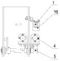
Fig. 2 is the structural representation of Fig. 1 embodiment.
Fig. 3 is the structural representation of Fig. 1 embodiment tripping mechanism.
Embodiment
Embodiment
The circuit breaker of present embodiment undervoltage tripping device as shown in Figure 1 to Figure 3, comprises undervoltage tripping loop, closing circuit and auxiliary switch QF;
The undervoltage tripping loop comprises first, second bridge rectifier V1, the V2 in parallel with the circuit breaker power supply, and tripping mechanism 4, and tripping mechanism 4 has under-voltage coil Y4; Be electrically connected with the under-voltage electromagnet Y6 with sensitive switch 1 between the both positive and negative polarity of the second bridge rectifier V2, sensitive switch 1 have first normally closed some S31 and first normal battle S32; Under-voltage coil Y4 and capacitor C are parallel between the both positive and negative polarity of the first bridge rectifier V1, under-voltage coil Y4 also with second of first normally closed some S31, the auxiliary switch QF of sensitive switch 1 often make war (61,62) connect;
Closing circuit comprises the 3rd bridge rectifier V3 with circuit breaker electric subject string connection, be parallel with first branch road and second branch road between the both positive and negative polarity of the 3rd bridge rectifier V3, the second normally closed point (13,14) of first route auxiliary switch QF, sensitive switch 1 first normal battle S32, and closing coil HQ series connection constitute, the 3rd of second route auxiliary switch QF often made war (11,12) and first resistance R, 0 series connection formation;
Auxiliary switch QF has second (61,62) and the 3rd gate-dividing state that (11,12) disconnect and the second normally closed point (13,14) is closed of often making war of often making war, and second (61,62) and the 3rd often the make war "on" position of (11,12) closure and the disconnection of the second normally closed point (13,14) of often making war;
Attonity state when tripping mechanism 4 has under-voltage coil Y4 dead electricity, and under-voltage coil Y4 gets and promotes the trip status that dropout semiaxis 5 makes auxiliary switch QF separating brake when electric.
In this structure, can cut off closing circuit in the undervoltage tripping loop during under-voltage or decompression, and make the auxiliary switch separating brake, make circuit breaker have higher safety performance.
Particularly, the undervoltage tripping loop also comprises second resistance R 1 of connecting with the shunt circuit of capacitor C and under-voltage coil Y4, the piezo-resistance R3 in parallel with capacitor C, the 3rd resistance R 2 of connecting with under-voltage electromagnet Y6.
Closing circuit also comprises the anti-trip relay K0 that connects with first resistance R 0, anti-trip relay K0 has jumper switch K0, and jumper switch K0 has the 3rd normally closed point that is series in first branch road, and often makes war (11,12) the 4th normal battle in parallel with auxiliary switch QF the 3rd; Jumper switch K0 has the normal condition that anti-trip relay K0 just often connects first branch road, and anti-trip relay K0 connects the anti-jump state of second branch road when unusual.
During use, this device can an independent control loop, both can directly draw power supply from voltage transformer, also can draw power supply by the secondary power distribution cabinet.
When circuit breaker is not switched on, undervoltage tripping loop no current, under-voltage electromagnet Y6 dead electricity, sensitive switch 1 is in the closed and first normal dissengaged positions that battle, S32 disconnected of first normally closed some S31, and first branch road of closing circuit disconnects, and circuit breaker can not close a floodgate.
Behind the breaker electrifying, when circuit breaker power supply voltage just often, in the undervoltage tripping loop under-voltage electromagnet Y6 get electric, sensitive switch 1 be in that first normally closed some S31 disconnects and first normal battle the S32 closure channel status, circuit breaker can normally close a floodgate, and capacitor C begins charging simultaneously.When circuit breaker power supply voltage descends when making the under-voltage or decompression in undervoltage tripping loop, under-voltage electromagnet Y6 dead electricity, sensitive switch 1 is in the closed and first normal dissengaged positions that battle, S32 disconnected of first normally closed some S31, capacitor C begins discharge that under-voltage coil Y4 is got is electric after first normally closed some S31 closure, and the moving iron core 2-2 that drives tripping mechanism 4 promotes dropout semiaxis 5 makes auxiliary switch QF separating brake; After first normal S32 disconnection battle, circuit breaker can not close a floodgate.
In addition to the implementation, the utility model can also have other execution modes.All employings are equal to the technical scheme of replacement or equivalent transformation formation, all drop on the protection range of the utility model requirement.
Claims (4)
Priority Applications (1)
| Application Number | Priority Date | Filing Date | Title |
|---|---|---|---|
| CN 201320146900 CN203192723U (en) | 2013-03-27 | 2013-03-27 | Undervoltage release device for circuit breaker |
Applications Claiming Priority (1)
| Application Number | Priority Date | Filing Date | Title |
|---|---|---|---|
| CN 201320146900 CN203192723U (en) | 2013-03-27 | 2013-03-27 | Undervoltage release device for circuit breaker |
Publications (1)
| Publication Number | Publication Date |
|---|---|
| CN203192723U true CN203192723U (en) | 2013-09-11 |
Family
ID=49109561
Family Applications (1)
| Application Number | Title | Priority Date | Filing Date |
|---|---|---|---|
| CN 201320146900 Expired - Fee Related CN203192723U (en) | 2013-03-27 | 2013-03-27 | Undervoltage release device for circuit breaker |
Country Status (1)
| Country | Link |
|---|---|
| CN (1) | CN203192723U (en) |
Cited By (3)
| Publication number | Priority date | Publication date | Assignee | Title |
|---|---|---|---|---|
| CN104833605A (en) * | 2015-05-20 | 2015-08-12 | 华北电力科学研究院有限责任公司 | Test equipment and method for burnout time of large granular fuel in fluidized bed |
| CN107843807A (en) * | 2016-09-20 | 2018-03-27 | 丰郅(上海)新能源科技有限公司 | A kind of moment in Voltage Drop can turn off the monitoring system of power network in time |
| CN113205981A (en) * | 2020-01-30 | 2021-08-03 | Abb瑞士股份有限公司 | Voltage measuring device |
-
2013
- 2013-03-27 CN CN 201320146900 patent/CN203192723U/en not_active Expired - Fee Related
Cited By (4)
| Publication number | Priority date | Publication date | Assignee | Title |
|---|---|---|---|---|
| CN104833605A (en) * | 2015-05-20 | 2015-08-12 | 华北电力科学研究院有限责任公司 | Test equipment and method for burnout time of large granular fuel in fluidized bed |
| CN107843807A (en) * | 2016-09-20 | 2018-03-27 | 丰郅(上海)新能源科技有限公司 | A kind of moment in Voltage Drop can turn off the monitoring system of power network in time |
| CN107843807B (en) * | 2016-09-20 | 2021-07-30 | 丰郅(上海)新能源科技有限公司 | Monitoring system capable of timely turning off power grid at voltage drop moment |
| CN113205981A (en) * | 2020-01-30 | 2021-08-03 | Abb瑞士股份有限公司 | Voltage measuring device |
Similar Documents
| Publication | Publication Date | Title |
|---|---|---|
| CN202512194U (en) | Sound and light alarm of circuit break | |
| CN203192723U (en) | Undervoltage release device for circuit breaker | |
| CN102693884B (en) | Special molded case circuit breaker for prepayment electric energy meter | |
| CN101888084A (en) | Open phase protector of motor | |
| CN102779612A (en) | Pre-magnetizing device for main power supply transformer of electric power circuit | |
| CN205070179U (en) | Electric blocking device of electric power low -voltage switchgear | |
| CN103384059A (en) | Vacuum circuit breaker energy storage motor protection circuit | |
| CN203774211U (en) | Automatic closing control circuit of universal circuit breaker | |
| CN202231403U (en) | Closing protection device of permanent magnet operating mechanism | |
| CN202384744U (en) | Full-stop protection device for cooler of forced oil-air cooling power transformer | |
| CN107689313A (en) | A kind of low-voltage circuit breaker | |
| CN207184025U (en) | Breaker emergency trip control circuit after dc source all disappears | |
| CN202585275U (en) | Novel secondary control circuit of permanent magnet structure | |
| CN106410741B (en) | A kind of omnipotent breaker from power transmission device | |
| CN204928360U (en) | A prevent shaking electric installation for series capacitance formula ac contactor | |
| CN202616164U (en) | Permanent magnet under-voltage release | |
| CN104616937B (en) | An arc extinguishing protection device for photovoltaic combiner box | |
| CN209981144U (en) | Emergency brake-separating delay re-actuating device of permanent magnet circuit breaker | |
| CN205177692U (en) | Novel permanent magnetism vacuum circuit breaker based on use electric protection | |
| CN201509070U (en) | Cable-fixed power-free micro-protector for motor | |
| CN202711902U (en) | Pre-magnetizing device for power supply main transformer of power line | |
| CN206148923U (en) | SPD backup protection ware | |
| CN107046272B (en) | Circuit breaker emergency trip control circuit and control method after all DC power disappears | |
| CN104992887A (en) | Under-voltage tripping device for permanent magnetic actuator circuit breakers | |
| CN104362578B (en) | Can reclosing RCCB |
Legal Events
| Date | Code | Title | Description |
|---|---|---|---|
| C14 | Grant of patent or utility model | ||
| GR01 | Patent grant | ||
| CF01 | Termination of patent right due to non-payment of annual fee | ||
| CF01 | Termination of patent right due to non-payment of annual fee |
Granted publication date: 20130911 Termination date: 20190327 |