CN202886456U - Capacitor voltage transformer fault monitoring instrument - Google Patents
Capacitor voltage transformer fault monitoring instrument Download PDFInfo
- Publication number
- CN202886456U CN202886456U CN 201220474893 CN201220474893U CN202886456U CN 202886456 U CN202886456 U CN 202886456U CN 201220474893 CN201220474893 CN 201220474893 CN 201220474893 U CN201220474893 U CN 201220474893U CN 202886456 U CN202886456 U CN 202886456U
- Authority
- CN
- China
- Prior art keywords
- voltage
- phase
- voltage transformer
- monitoring instrument
- amplitude
- Prior art date
- Legal status (The legal status is an assumption and is not a legal conclusion. Google has not performed a legal analysis and makes no representation as to the accuracy of the status listed.)
- Expired - Fee Related
Links
Images


Landscapes
- Testing Of Short-Circuits, Discontinuities, Leakage, Or Incorrect Line Connections (AREA)
Abstract
本实用新型公开了一种电容式电压互感器故障监测仪表,该仪表能够采集三相电容式电压互感器的三相二次电压,并通过对所述三相二次电压的处理计算,得到需要了解的参数信息,最后根据所述参数判断电容式电压互感器是否存在异常和故障。本实用新型实施例公开的电容式电压互感器故障监测仪在应用时直接连接于电力设备上,不需要改变原有的电力设备结构,且故障判断依据的参数直接由电容式电压互感器输出电压计算而来,参数稳定可靠,整体降低了电力系统的运行风险,提高了系统可靠性。
The utility model discloses a capacitive voltage transformer fault monitoring instrument, which can collect the three-phase secondary voltage of the three-phase capacitive voltage transformer, and obtain the required voltage by processing and calculating the three-phase secondary voltage. After knowing the parameter information, finally judge whether there is abnormality or fault in the capacitive voltage transformer according to the parameter. The capacitive voltage transformer fault monitor disclosed in the embodiment of the utility model is directly connected to the power equipment during application, without changing the original power equipment structure, and the parameters based on the fault judgment are directly output by the capacitive voltage transformer Based on the calculation, the parameters are stable and reliable, which reduces the operation risk of the power system as a whole and improves the system reliability.
Description
技术领域 technical field
本实用新型涉及电容式电压互感器领域,更具体的说,是涉及一种电容式电压互感器故障监测仪表。The utility model relates to the field of capacitive voltage transformers, in particular to a fault monitoring instrument for capacitive voltage transformers.
背景技术 Background technique
电容式电压互感器是一个带电容分压器和铁心的变压器,主要由电容分压器、一次线圈、二次线圈、铁心和绝缘组成。图1为电容式电压互感器在电网中的安装连接示意图,如图1所示,电容式电压互感器在变电站内通常采用三相对称安装的方式布置,其一次线圈和二次线圈上不同的绕组匝数,可以将高电压按一次绕组匝数与二次绕组匝数的比例转换成低电压。因此,电容式电压互感器是由电容分压器和中间电压电磁单元组成的具有独特结构的电气设备,兼具电压互感器和电力线路载波耦合装置两种设备的功能,广泛用于110KV及以上电压等级的变电站内。Capacitive voltage transformer is a transformer with capacitive voltage divider and iron core, mainly composed of capacitive voltage divider, primary coil, secondary coil, iron core and insulation. Figure 1 is a schematic diagram of the installation and connection of the capacitor voltage transformer in the power grid. As shown in Figure 1, the capacitor voltage transformer is usually arranged in a three-phase symmetrical installation in the substation, and the primary coil and the secondary coil are different. The number of winding turns can convert the high voltage into a low voltage according to the ratio of the number of turns of the primary winding to the number of turns of the secondary winding. Therefore, the capacitive voltage transformer is an electrical device with a unique structure composed of a capacitive voltage divider and an intermediate voltage electromagnetic unit. It has the functions of a voltage transformer and a power line carrier coupling device. It is widely used in 110KV and above In the substation of the voltage level.
一般来说,电容式电压互感器的正常工作是保障电网参数测量工作的重要前提。因此,对电容式电压互感器故障的监测工作也尤为重要。在现有技术中,电容式电压互感器的监测工作主要包括泄漏电流、本体介损和本体电容量的监测。但是,上述对电容式电压互感器泄漏电流、本体介损和本体电容量的监测,都需要将被监测的信号从电力设备的末屏中引出,进而对引出的信号进行分析,判断出电压互感器是否存在故障。然而要实现将被监测信号从末屏中引出的这个过程,就必须改变电力设备的末屏结构。Generally speaking, the normal operation of capacitive voltage transformers is an important prerequisite for ensuring the measurement of power grid parameters. Therefore, it is particularly important to monitor the faults of capacitive voltage transformers. In the prior art, the monitoring work of the capacitive voltage transformer mainly includes the monitoring of the leakage current, the dielectric loss of the body and the capacitance of the body. However, the above-mentioned monitoring of the leakage current of the capacitive voltage transformer, the dielectric loss of the body, and the capacitance of the body all need to extract the monitored signal from the end screen of the power equipment, and then analyze the extracted signal to determine the voltage mutual inductance. device is faulty. However, in order to realize the process of deriving the monitored signal from the end screen, it is necessary to change the structure of the end screen of the power equipment.
综上所述可以看出,现有技术中监测电容式电压互感器的方法需要改变电力设备结构,且本体介损和本体电容量的在线监测本身容易受到天气和温度的影响,从而使得运行风险增大,可靠性降低。To sum up, it can be seen that the method of monitoring capacitive voltage transformers in the prior art needs to change the structure of power equipment, and the on-line monitoring of body dielectric loss and body capacitance itself is easily affected by weather and temperature, which makes the operation risk increase, the reliability decreases.
实用新型内容Utility model content
有鉴于此,本实用新型提供了一种电容式电压互感器故障监测仪表,以克服现有技术中由于监测电压互感器故障需要改变设备结构,且被监测参数受环境影响而导致的系统运行风险高,可靠性低的问题。In view of this, the utility model provides a capacitive voltage transformer fault monitoring instrument to overcome the system operation risk caused by the need to change the equipment structure due to monitoring the voltage transformer fault in the prior art, and the monitored parameters are affected by the environment High and low reliability issues.
为实现上述目的,本实用新型提供如下技术方案:In order to achieve the above object, the utility model provides the following technical solutions:
一种电容式电压互感器故障监测仪表,包括:A capacitive voltage transformer fault monitoring instrument, comprising:
采集三相电容式电压互感器的每一相的二次电压的数据采集器;A data collector for collecting the secondary voltage of each phase of the three-phase capacitive voltage transformer;
与所述数据采集器连接,处理所述每一相的二次电压得到三相开口三角电压、电压不平衡度和电压互感器幅值中的任意一个或多个参数,判断所述三相开口三角电压、电压不平衡度和电压互感器幅值中的任一个或多个是否超出预设标准范围,并在判断结果为是时,发出相应的越限警报的处理器。Connect with the data collector, process the secondary voltage of each phase to obtain any one or more parameters of the three-phase open triangle voltage, voltage unbalance and voltage transformer amplitude, and judge the three-phase open Whether any one or more of the triangular voltage, voltage unbalance degree and voltage transformer amplitude exceeds the preset standard range, and if the judgment result is yes, a processor that sends out a corresponding limit alarm.
可选的,所述处理器包括:Optionally, the processor includes:
计算所述三相电容式电压互感器三相开口处的两根电源线上的电压值的矢量差值,并将所述矢量差值作为三相开口三角电压的第一单片机;Calculate the vector difference of the voltage values on the two power lines at the three-phase opening of the three-phase capacitive voltage transformer, and use the vector difference as the first single-chip microcomputer of the three-phase opening triangle voltage;
与所述第一单片机连接,判断所述三相开口三角电压的幅值是否超出预设的三相开口三角电压范围的第一比较器;A first comparator that is connected to the first single-chip microcomputer and judges whether the amplitude of the three-phase open-triangular voltage exceeds a preset three-phase open-triangular voltage range;
与所述第一比较器连接,在所述第一比较器的判断结果为是的情况下,发出三相开口电压越限警报的第一报警器。It is connected with the first comparator, and in the case that the judgment result of the first comparator is yes, the first alarm device sends out a three-phase open voltage over-limit alarm.
可选的,所述处理器包括:Optionally, the processor includes:
计算任意两相二次电压的幅值绝对值差值,并将所述差值除以所述任意两相中的任意一相的二次电压幅值,得到电压不平衡度的第二单片机;calculating the difference in the absolute value of the amplitude of the secondary voltage of any two phases, and dividing the difference by the secondary voltage amplitude of any one of the two phases to obtain the second single-chip microcomputer of the voltage unbalance;
与所述第二单片机连接,判断所述电压不平衡度是否超出预设的电压不平衡度范围的第二比较器;A second comparator connected to the second single-chip microcomputer to determine whether the voltage unbalance exceeds a preset range of voltage unbalance;
与所述第二比较器连接,在所述第二比较器的判断结果为是的情况下,发出电压不平衡度越限警报的第二报警器。It is connected with the second comparator, and if the judgment result of the second comparator is yes, a second alarm device that issues a voltage unbalance degree over-limit alarm.
可选的,所述处理器包括:Optionally, the processor includes:
判断任意一相的二次电压幅值是否超出预设的电压互感器幅值范围的第三比较器;A third comparator for judging whether the secondary voltage amplitude of any phase exceeds the preset voltage transformer amplitude range;
与所述第三比较器连接,在所述第三比较器的判断结果为是的情况下,发出电压互感器幅值越限警报的第三报警器。It is connected with the third comparator, and if the judgment result of the third comparator is yes, it is a third alarm device that issues a voltage transformer amplitude over-limit alarm.
可选的,还包括:Optionally, also include:
与所述处理器相连,存储有越限警报信号与故障类别对应关系表的存储器。Connected with the processor, there is a memory storing a table of correspondences between alarm signals exceeding limits and fault categories.
可选的,还包括:Optionally, also include:
与所述处理器相连,依据所述越限警报信号与故障类别对应关系表中的对应关系,根据出现的越限警报信号查找出与所述越限警报信号对应的故障类别,并显示所述故障类别的显示器。Connected to the processor, according to the corresponding relationship between the over-limit alarm signal and the fault category correspondence table, find out the fault category corresponding to the over-limit alarm signal according to the occurrence of the over-limit alarm signal, and display the Display of fault categories.
可选的,所述显示器为在所述处理器的判断结果为否的情况下,输出参数正常指示信息的显示器。Optionally, the display is a display that outputs parameter normal indication information when the judgment result of the processor is negative.
可选的,所述数据采集器为四通道数据采集器。Optionally, the data collector is a four-channel data collector.
可选的,所述报警器为LED灯和蜂鸣器中的至少一种。Optionally, the alarm is at least one of an LED light and a buzzer.
经由上述的技术方案可知,与现有技术相比,本实用新型实施例公开了一种电容式电压互感器故障监测仪表,该仪表能够采集三相电容式电压互感器的三相二次电压,并通过对所述三相二次电压的处理计算,得到需要了解的参数信息,最后根据所述参数判断电容式电压互感器是否存在异常和故障。本实用新型实施例公开的电容式电压互感器故障监测仪在应用时直接连接于电力设备上,不需要改变原有的电力设备结构,且故障判断依据的参数直接由电容式电压互感器输出电压计算而来,参数稳定可靠,整体降低了电力系统的运行风险,提高了系统可靠性。It can be known from the above technical solutions that, compared with the prior art, the embodiment of the utility model discloses a capacitive voltage transformer fault monitoring instrument, which can collect the three-phase secondary voltage of the three-phase capacitive voltage transformer, And by processing and calculating the three-phase secondary voltage, obtain the parameter information that needs to be known, and finally judge whether there is abnormality or failure in the capacitive voltage transformer according to the parameters. The capacitive voltage transformer fault monitor disclosed in the embodiment of the utility model is directly connected to the power equipment during application, without changing the original power equipment structure, and the parameters based on the fault judgment are directly output by the capacitive voltage transformer Based on the calculation, the parameters are stable and reliable, which reduces the operation risk of the power system as a whole and improves the system reliability.
附图说明 Description of drawings
为了更清楚地说明本实用新型实施例或现有技术中的技术方案,下面将对实施例或现有技术描述中所需要使用的附图作简单地介绍,显而易见地,下面描述中的附图仅仅是本实用新型的实施例,对于本领域普通技术人员来讲,在不付出创造性劳动的前提下,还可以根据提供的附图获得其他的附图。In order to more clearly illustrate the technical solutions in the embodiments of the present invention or the prior art, the following will briefly introduce the accompanying drawings that need to be used in the description of the embodiments or the prior art. Obviously, the accompanying drawings in the following description It is only an embodiment of the utility model, and those skilled in the art can also obtain other drawings according to the provided drawings without creative work.
图1为电容式电压互感器在电网中的安装连接示意图;Figure 1 is a schematic diagram of the installation and connection of a capacitive voltage transformer in a grid;
图2为本实用新型实施例公开的电容式电压互感器故障监测仪表第一结构示意图;Fig. 2 is a schematic diagram of the first structure of the capacitive voltage transformer fault monitoring instrument disclosed in the embodiment of the present invention;
图3为本实用新型实施例公开的电容式电压互感器故障监测仪表的接线示意图;Fig. 3 is the schematic wiring diagram of the capacitive voltage transformer fault monitoring instrument disclosed by the embodiment of the present invention;
图4为本实用新型实施例公开的处理器第一结构示意图;Fig. 4 is a schematic diagram of the first structure of the processor disclosed in the embodiment of the present invention;
图5为图4所示实施例中计算三相开口三角电压并报警的流程图;Fig. 5 is the flowchart of calculating three-phase open triangle voltage and reporting to the police in the embodiment shown in Fig. 4;
图6为本实用新型实施例公开的处理器第二结构示意图;Fig. 6 is a schematic diagram of the second structure of the processor disclosed in the embodiment of the present invention;
图7为图6所示实施例中计算电压不平衡度并报警的流程图;Fig. 7 is the flow chart of calculating voltage unbalance degree and reporting to the police in the embodiment shown in Fig. 6;
图8为本实用新型实施例公开的处理器第三结构示意图;Fig. 8 is a schematic diagram of the third structure of the processor disclosed in the embodiment of the present invention;
图9为图8所示实施例中计算电压互感器幅值并报警的流程图;Fig. 9 is the flowchart of calculating voltage transformer amplitude and reporting to the police in the embodiment shown in Fig. 8;
图10为本实用新型实施例公开的电容式电压互感器故障监测仪表第二结构示意图。Fig. 10 is a schematic diagram of the second structure of the capacitive voltage transformer fault monitoring instrument disclosed in the embodiment of the present invention.
具体实施方式 Detailed ways
下面将结合本实用新型实施例中的附图,对本实用新型实施例中的技术方案进行清楚、完整地描述,显然,所描述的实施例仅仅是本实用新型一部分实施例,而不是全部的实施例。基于本实用新型中的实施例,本领域普通技术人员在没有做出创造性劳动前提下所获得的所有其他实施例,都属于本实用新型保护的范围。The technical solutions in the embodiments of the present invention will be clearly and completely described below in conjunction with the accompanying drawings in the embodiments of the present invention. Obviously, the described embodiments are only part of the embodiments of the present invention, not all of them. example. Based on the embodiments of the present utility model, all other embodiments obtained by persons of ordinary skill in the art without making creative efforts belong to the scope of protection of the present utility model.
实施例一Embodiment one
如图1所示,本实施中与三相母线连接的电容式电压互感器采用三相对称安装的方式。As shown in Figure 1, the capacitive voltage transformer connected to the three-phase busbar in this implementation adopts a three-phase symmetrical installation method.
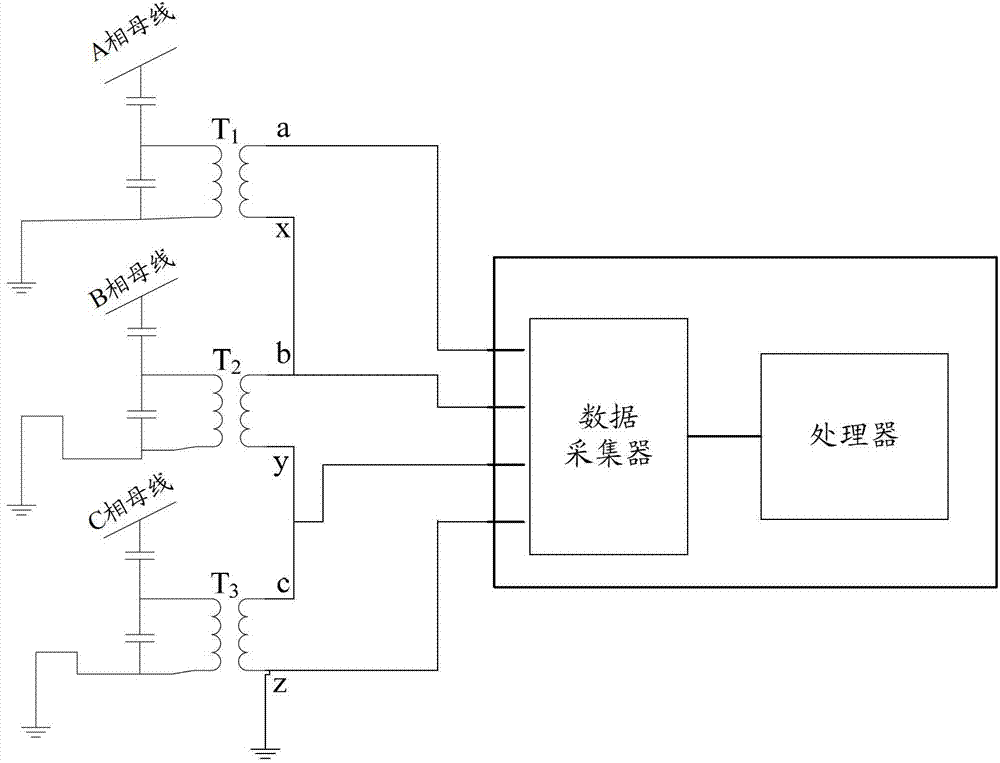
图2为本实用新型实施例公开的电容式电压互感器故障监测仪表结构示意图,图3为本实用新型实施例公开的电容式电压互感器故障监测仪表的接线示意图,参见图2和图3所示,所述电容式电压互感器故障监测仪表20可以包括:Fig. 2 is a schematic structural diagram of a capacitive voltage transformer fault monitoring instrument disclosed in an embodiment of the utility model, and Fig. 3 is a schematic wiring diagram of a capacitive voltage transformer fault monitoring instrument disclosed in an embodiment of the utility model, see Fig. 2 and Fig. 3 As shown, the capacitive voltage transformer
采集三相电容式电压互感器的每一相的二次电压的数据采集器201。A
参见图3所示,本实施例中,三相电容式电压互感器采用开口三角形法连接,A相电容式电压互感器T1二次侧的两个管脚为a和x,B相电容式电压互感器T2二次侧的两个管脚为b和y,C相电容式电压互感器T3二次侧的两个管脚为c和z,共有6个管脚;将x管脚和b管脚相连,并将y管脚和c管脚相连,最终得到4个管脚,因此,本实施例中的数据采集器可以为四通道的数据采集器,分别连接上述4个管脚,将a管脚输出电压记为U1,x-b管脚输出电压记为U2,c管脚输出电压记为U3,z管脚输出电压记为U4,则A相二次电压值为U1和U2的矢量差值,B相二次电压值为U2和U3的矢量差值,C相二次电压值为U3和U4的矢量差值。Referring to Figure 3, in this embodiment, the three-phase capacitive voltage transformers are connected using the open triangle method, the two pins on the secondary side of the A-phase capacitive voltage transformer T1 are a and x, and the B-phase capacitive voltage transformer The two pins on the secondary side of the transformer T2 are b and y, and the two pins on the secondary side of the C-phase capacitive voltage transformer T3 are c and z, with a total of 6 pins; the x pin and the b tube Pins are connected, and the y pins are connected with the c pins to finally obtain 4 pins. Therefore, the data collector in this embodiment can be a four-channel data collector, which is connected to the above 4 pins respectively, and a The output voltage of the pin is recorded as U1, the output voltage of the x-b pin is recorded as U2, the output voltage of the c pin is recorded as U3, and the output voltage of the z pin is recorded as U4, then the secondary voltage value of the A phase is the vector difference between U1 and U2 , the B-phase secondary voltage value is the vector difference between U2 and U3, and the C-phase secondary voltage value is the vector difference between U3 and U4.
所述电容式电压互感器故障监测仪除了数据采集器201外,还包括与所述数据采集器连接,处理所述每一相的二次电压得到三相开口三角电压、电压不平衡度和电压互感器幅值中任一个或多个参数,判断所述三相开口三角电压、电压不平衡度和电压互感器幅值中的任一个或多个是否超出标准范围,并在判断结果为是时,发出相应的越限警报的处理器202。In addition to the
所述处理器202能够根据所述数据采集器201四个通道采集到的U1、U2、U3和U4,计算出三相电容式电压互感器的三相开口三角电压、电压不平衡度和电压互感器幅值,并判断其是否超出预设标准范围;下面将结合所述处理器202所包含的结构依次介绍三相电容式电压互感器的三相开口三角电压、电压不平衡度和电压互感器幅值的计算方法。The
图4为本实用新型实施例公开的处理器第一结构示意图,图5为图4所示实施例中计算三相开口三角电压并报警的流程图,参见图4和图5所示,所述处理器202可以包括:Fig. 4 is a schematic diagram of the first structure of the processor disclosed in the embodiment of the present invention, and Fig. 5 is a flow chart of calculating the three-phase open triangle voltage and giving an alarm in the embodiment shown in Fig. 4, referring to Fig. 4 and Fig. 5, the described
计算所述三相电容式电压互感器三相开口处的两根电源线上的电压值的矢量差值,并将所述矢量差值作为三相开口三角电压的第一单片机401。The first single-chip microcomputer 401 that calculates the vector difference of the voltage values on the two power lines at the three-phase opening of the three-phase capacitive voltage transformer, and uses the vector difference as the triangular voltage of the three-phase opening.
本实施例中,三相开口三角电压为三相电压和,三相电压和的计算公式为U0=U1-U2+U2-U3+U3-U4,即U0=U1-U4=U14;因此,三相开口三角电压的值等于三相电容式电压互感器三相开口处的两根电源线上的电压值的矢量差值。In this embodiment, the three-phase open triangle voltage is the sum of the three-phase voltages, and the calculation formula for the sum of the three-phase voltages is U0=U1-U2+U2-U3+U3-U4, that is, U0=U1-U4=U14; therefore, three The value of the delta voltage at the phase opening is equal to the vector difference of the voltage values on the two power lines at the three-phase opening of the three-phase capacitive voltage transformer.
与所述第一单片机连接,判断所述三相开口三角电压的幅值是否超过预设的三相开口三角电压范围的第一比较器402。The first comparator 402 is connected with the first single-chip microcomputer and judges whether the amplitude of the three-phase open-triangular voltage exceeds a preset three-phase open-triangular voltage range.
其中,所述预设的三相开口三角电压范围可以为运行工作人员根据以往经验设置的;正常情况下,三相开口三角电压的范围为1.5-3V。Wherein, the preset three-phase open-delta voltage range can be set by operating personnel based on previous experience; under normal circumstances, the three-phase open-delta voltage range is 1.5-3V.
与所述第一比较器连接,在所述第一比较器的判断结果为是的情况下,发出三相开口电压越限警报的第一报警器403。It is connected with the first comparator, and if the judgment result of the first comparator is yes, the first alarm device 403 that issues a three-phase open voltage over-limit alarm.
在所述第一单片机401计算得到的三相开口三角电压U0超出了其正常范围,说明三相电容式电压互感器存在故障,例如内部绝缘故障,发出三相开口三角电压越限警报信息。The three-phase open-delta voltage U0 calculated by the first single-chip microcomputer 401 exceeds its normal range, indicating that there is a fault in the three-phase capacitive voltage transformer, such as an internal insulation fault, and a three-phase open-delta voltage over-limit alarm message is issued.
需要说明的是,本实用新型实施例公开处理器的结构并不局限于上述结构,在实际应用中,所述第一单片机和所述第一比较器可以是合成于一体的一个具体结构,例如同时具有计算和比较功能的一个单片机,当然,所述第一单片机和所述第一比较器也可以是上述相互独立的两个结构。在不脱离本实用新型整体设计思想的基础上的处理结构,都应属于本实用新型的保护范围。It should be noted that the structure of the processor disclosed in the embodiment of the present utility model is not limited to the above-mentioned structure. In practical applications, the first single-chip microcomputer and the first comparator can be a specific structure integrated into one body, for example A single-chip microcomputer having calculation and comparison functions at the same time, of course, the first single-chip microcomputer and the first comparator can also be the above two independent structures. The processing structure on the basis of not departing from the overall design idea of the utility model should belong to the protection scope of the utility model.
图6为本实用新型实施例公开的处理器第二结构示意图,图7为图6所示实施例中计算电压不平衡度并报警的流程图,参见图6和图7所示,所述处理器202可以包括:Fig. 6 is a schematic diagram of the second structure of the processor disclosed in the embodiment of the present invention, and Fig. 7 is a flow chart of calculating voltage unbalance degree and alarming in the embodiment shown in Fig. 6 , referring to Fig. 6 and Fig. 7 , the
计算任意两相二次电压的幅值绝对值差值,并将所述差值除以所述任意两相中的任意一相的二次电压幅值,得到电压不平衡度的第二单片机601;Calculate the difference in the absolute value of the magnitude of the secondary voltage of any two phases, and divide the difference by the magnitude of the secondary voltage of any one of the two phases to obtain the second single-chip microcomputer 601 of the voltage unbalance ;
其中,任意两相可以是A、B相,也可以是B、C相和A、C相,其计算方法相似,在此以A、B相为例来介绍其计算方法。所述第二单片机601获取U1、U2和U3,首先计算出U1和U2的矢量差U12,再计算出U2和U3的矢量差U23,最后计算得到U12和U23的电压幅值绝对值的差值,再将计算得到的所述差值除以U12,得到A相电压不平衡度;将计算得到的所述差值除以U23,得到B相电压不平衡度。Among them, any two phases can be phases A and B, or phases B and C and phases A and C, and the calculation methods are similar. Here, phases A and B are used as examples to introduce the calculation methods. The second single-chip microcomputer 601 obtains U1, U2 and U3, first calculates the vector difference U12 of U1 and U2, then calculates the vector difference U23 of U2 and U3, and finally calculates the difference between the absolute value of the voltage amplitude of U12 and U23 , and then divide the calculated difference by U12 to obtain the A-phase voltage unbalance; divide the calculated difference by U23 to obtain the B-phase voltage unbalance.
与所述第二单片机连接,判断所述电压不平衡度是否超出预设的电压不平衡度范围的第二比较器602。A second comparator 602 that is connected to the second single-chip microcomputer and judges whether the voltage unbalance degree exceeds a preset voltage unbalance degree range.
其中,所述预设的电压不平衡度范围可以为运行工作人员根据以往经验设置的;正常情况下,电压不平衡度的范围为3%—5%。Wherein, the preset range of the voltage unbalance degree can be set by the operating staff based on previous experience; under normal circumstances, the range of the voltage unbalance degree is 3%-5%.
与所述第二比较器连接,在所述第二比较器的判断结果为是的情况下,发出电压不平衡度越限警报的第二报警器603。It is connected with the second comparator, and if the judgment result of the second comparator is yes, a second alarm device 603 that issues a voltage unbalance degree over-limit alarm.
在所述第二单片机601计算得到的电压不平衡度超出了其正常范围,说明三相电容式电压互感器存在故障,发出电压不平衡度越限警报信息。当然,如果所述幅值绝对值差值除以U12得到的值超过了5%,则发出A相电压不平衡度越限警报信息;如果所述幅值绝对值差值除以U23得到的值超过了5%,则发出B相电压不平衡度越限警报信息。The voltage unbalance degree calculated by the second single-chip microcomputer 601 exceeds its normal range, indicating that there is a fault in the three-phase capacitive voltage transformer, and a voltage unbalance degree exceeding a limit alarm message is issued. Of course, if the value obtained by dividing the absolute value of the amplitude by U12 exceeds 5%, an alarm message will be issued for the phase A voltage unbalance; if the value obtained by dividing the absolute value of the amplitude by U23 If it exceeds 5%, an alarm message for exceeding the limit of the B-phase voltage imbalance will be issued.
需要说明的是,本实用新型实施例公开处理器的结构并不局限于上述结构,在实际应用中,所述第二单片机和所述第二比较器可以是合成于一体的一个具体结构,例如同时具有计算和比较功能的一个单片机,当然,所述第二单片机和所述第二比较器也可以是上述相互独立的两个结构。在不脱离本实用新型整体设计思想的基础上的处理结构,都应属于本实用新型的保护范围。It should be noted that the structure of the processor disclosed in the embodiment of the present utility model is not limited to the above-mentioned structure. In practical applications, the second single-chip microcomputer and the second comparator can be a specific structure integrated into one body, for example A single-chip microcomputer having calculation and comparison functions at the same time, of course, the second single-chip microcomputer and the second comparator can also be the above two independent structures. The processing structure on the basis of not departing from the overall design idea of the utility model should belong to the protection scope of the utility model.
图8为本实用新型实施例公开的处理器第三结构示意图,图9为图8所示实施例中计算电压互感器幅值并报警的流程图,参见图8和图9所示,所述处理器202可以包括:Fig. 8 is a schematic diagram of the third structure of the processor disclosed in the embodiment of the present invention, and Fig. 9 is a flow chart of calculating the voltage transformer amplitude and alarming in the embodiment shown in Fig. 8, referring to Fig. 8 and Fig. 9, the
判断任意一相的二次电压幅值是否超出预设的电压互感器幅值范围的第三比较器801。A
需要判断哪一相的幅值是否超范围时,就选取对应的二次电压输出信号,例如,判断B相二次电压幅值是否超标时,计算U2和U3的矢量差值U23,将U23的幅值与预设的电压互感器幅值进行比较。When it is necessary to judge whether the amplitude of which phase exceeds the range, select the corresponding secondary voltage output signal. For example, when judging whether the amplitude of the secondary voltage of phase B exceeds the standard, calculate the vector difference U23 between U2 and U3, and convert the U23 The magnitude is compared with the preset voltage transformer magnitude.
与所述第三比较器连接,在所述第三比较器的判断结果为是的情况下,发出电压互感器幅值越限警报的第三报警器802。It is connected with the third comparator, and if the judgment result of the third comparator is yes, a
在U23电容式电压互感器的二次电压幅值超出了其正常范围,说明B相电容式电压互感器存在故障,例如内部绝缘故障,发出B相电容式电压互感器幅值越限警报信息。The secondary voltage amplitude of the U23 capacitive voltage transformer exceeds its normal range, indicating that there is a fault in the B-phase capacitive voltage transformer, such as an internal insulation fault, and an alarm message is issued for the amplitude of the B-phase capacitive voltage transformer.
需要说明的是,上述第一报警器、第二报警器和第三报警器的具体实现可以是LED灯,也可以是蜂鸣器,也可以是LED灯和蜂鸣器的结合;可以将不同参数的报警信号设置成不同颜色的LED灯和/或不同频率的声音。It should be noted that the specific implementation of the first alarm, the second alarm and the third alarm can be LED lights, buzzers, or a combination of LED lights and buzzers; different The alarm signals of the parameters are set as LED lights of different colors and/or sounds of different frequencies.
本实施例中,所述电容式电压互感器故障监测仪表能够采集三相电容式电压互感器的三相二次电压,并通过对所述三相二次电压的处理计算,得到需要了解的参数信息,最后根据所述参数判断电容式电压互感器是否存在异常和故障。电容式电压互感器故障监测仪在应用时直接连接于电力设备上,不需要改变原有的电力设备结构,且故障判断依据的参数直接由电容式电压互感器输出电压计算而来,参数稳定可靠,整体降低了电力系统的运行风险,提高了系统可靠性。In this embodiment, the capacitive voltage transformer fault monitoring instrument can collect the three-phase secondary voltage of the three-phase capacitive voltage transformer, and obtain the parameters that need to be understood by processing and calculating the three-phase secondary voltage information, and finally determine whether there is abnormality or fault in the capacitive voltage transformer according to the parameters. The capacitive voltage transformer fault monitor is directly connected to the power equipment during application, without changing the original power equipment structure, and the parameters based on the fault judgment are directly calculated from the output voltage of the capacitive voltage transformer, and the parameters are stable and reliable , the overall operation risk of the power system is reduced, and the system reliability is improved.
实施例二Embodiment two
图10为本实用新型实施例公开的电容式电压互感器故障监测仪表第二结构示意图,参见图10所示,所述电容式电压互感器故障监测仪表100可以包括:Fig. 10 is a schematic diagram of the second structure of the capacitive voltage transformer fault monitoring instrument disclosed in the embodiment of the present invention. Referring to Fig. 10, the capacitive voltage transformer
采集三相电容式电压互感器的每一相的二次电压的数据采集器201。A
与所述数据采集器连接,处理所述每一相的二次电压得到三相开口三角电压、电压不平衡度和电压互感器幅值中的任意一个或多个参数,判断所述三相开口三角电压、电压不平衡度和电压互感器幅值中的任一个或多个是否超出预设标准范围,并在判断结果为是时,发出相应的越限警报的处理器202。Connect with the data collector, process the secondary voltage of each phase to obtain any one or more parameters of the three-phase open triangle voltage, voltage unbalance and voltage transformer amplitude, and judge the three-phase open Whether any one or more of the triangular voltage, voltage unbalance degree and voltage transformer amplitude exceeds the preset standard range, and if the judgment result is yes, the
与所述处理器202连接,存储有越限警报信号与故障类别对应关系表的存储器203。Connected with the
其中,一种报警信号可能对应多个可能的故障,例如,在出现三相开口三角电压越限警报信号时,可能的故障有电容式电压互感器内部绝缘故障和漏电故障。Wherein, one alarm signal may correspond to multiple possible faults. For example, when a three-phase open-triangular voltage over-limit alarm signal occurs, the possible faults include internal insulation fault and leakage fault of the capacitor voltage transformer.
与所述处理器202连接,依据所述越限警报信号与故障类别对应关系表中的对应关系,根据出现的越限警报信号查找出与所述越限警报信号对应的故障类别,并显示所述故障类别的显示器204。Connected to the
当出现的越限警报信号对应多个可能的故障时,运维工作人员需要根据实际情况依次检查可能出现的故障,直到找到真正的故障所在。When the over-limit alarm signal corresponds to multiple possible faults, the operation and maintenance staff need to check the possible faults in turn according to the actual situation until the real fault is found.
所述显示器还可以用于在所述处理器202判断结果为否的情况下,输出参数正常指示信息的显示器。The display can also be used to output parameter normal indication information when the judgment result of the
可以直接通过显示屏输出参数正常字样,同时显示计算得到的三相开口三角电压、电压不平衡度和电压互感器幅值中任意一个或多个的数值。It can directly output the normal word of the parameter through the display screen, and at the same time display any one or more values of the calculated three-phase open triangle voltage, voltage unbalance degree and voltage transformer amplitude.
本实施例中,电容式电压互感器故障监测仪表根据采集到的三相电容式电压互感器的三相二次电压,计算得到需要了解的参数信息,最后根据所述参数判断电容式电压互感器是否存在异常和故障。该电容式电压互感器故障监测仪表在应用时直接连接于电力设备上,不需要改变原有的电力设备结构,且故障判断依据的参数直接由电容式电压互感器输出电压计算而来,参数稳定可靠,整体降低了电力系统的运行风险,提高了系统可靠性。同时该电容式电压互感器故障监测仪表能够预测可能的故障类型,并通过显示设备将信息传达给用户,便于用户方便快速的定位故障并排除故障。In this embodiment, the capacitive voltage transformer fault monitoring instrument calculates the parameter information that needs to be understood according to the collected three-phase secondary voltage of the three-phase capacitive voltage transformer, and finally judges the capacitive voltage transformer according to the parameters Whether there are abnormalities and malfunctions. The capacitive voltage transformer fault monitoring instrument is directly connected to the power equipment during application, without changing the original power equipment structure, and the parameters based on the fault judgment are directly calculated from the output voltage of the capacitive voltage transformer, and the parameters are stable Reliable, the overall operation risk of the power system is reduced, and the system reliability is improved. At the same time, the capacitive voltage transformer fault monitoring instrument can predict possible fault types, and communicate the information to the user through the display device, which is convenient for the user to locate and troubleshoot the fault conveniently and quickly.
本说明书中各个实施例采用递进的方式描述,每个实施例重点说明的都是与其他实施例的不同之处,各个实施例之间相同相似部分互相参见即可。Each embodiment in this specification is described in a progressive manner, each embodiment focuses on the difference from other embodiments, and the same and similar parts of each embodiment can be referred to each other.
还需要说明的是,在本文中,诸如第一和第二等之类的关系术语仅仅用来将一个实体或者操作与另一个实体或操作区分开来,而不一定要求或者暗示这些实体或操作之间存在任何这种实际的关系或者顺序。而且,术语“包括”、“包含”或者其任何其他变体意在涵盖非排他性的包含,从而使得包括一系列要素的物品或者设备不仅包括那些要素,而且还包括没有明确列出的其他要素,或者是还包括为这种物品或者设备所固有的要素。在没有更多限制的情况下,由语句“包括一个……”限定的要素,并不排除在包括所述要素的物品或者设备中还存在另外的相同要素。It should also be noted that in this article, relational terms such as first and second etc. are only used to distinguish one entity or operation from another entity or operation, and do not necessarily require or imply that these entities or operations Any such actual relationship or order exists between. Moreover, the term "comprises", "comprises" or any other variation thereof is intended to cover a non-exclusive inclusion such that an article or device comprising a set of elements includes not only those elements but also other elements not expressly listed, Or also include elements inherent in the article or device. Without further limitations, an element defined by the phrase "comprising a" does not exclude the presence of additional identical elements in the article or device comprising said element.
对所公开的实施例的上述说明,使本领域专业技术人员能够实现或使用本实用新型。对这些实施例的多种修改对本领域的专业技术人员来说将是显而易见的,本文中所定义的一般原理可以在不脱离本实用新型的精神或范围的情况下,在其它实施例中实现。因此,本实用新型将不会被限制于本文所示的这些实施例,而是要符合与本文所公开的原理和新颖特点相一致的最宽的范围。The above description of the disclosed embodiments enables those skilled in the art to realize or use the utility model. Various modifications to these embodiments will be readily apparent to those skilled in the art, and the general principles defined herein may be implemented in other embodiments without departing from the spirit or scope of the invention. Therefore, the present invention will not be limited to these embodiments shown herein, but will conform to the widest scope consistent with the principles and novel features disclosed herein.
Claims (9)
Priority Applications (1)
| Application Number | Priority Date | Filing Date | Title |
|---|---|---|---|
| CN 201220474893 CN202886456U (en) | 2012-09-17 | 2012-09-17 | Capacitor voltage transformer fault monitoring instrument |
Applications Claiming Priority (1)
| Application Number | Priority Date | Filing Date | Title |
|---|---|---|---|
| CN 201220474893 CN202886456U (en) | 2012-09-17 | 2012-09-17 | Capacitor voltage transformer fault monitoring instrument |
Publications (1)
| Publication Number | Publication Date |
|---|---|
| CN202886456U true CN202886456U (en) | 2013-04-17 |
Family
ID=48077868
Family Applications (1)
| Application Number | Title | Priority Date | Filing Date |
|---|---|---|---|
| CN 201220474893 Expired - Fee Related CN202886456U (en) | 2012-09-17 | 2012-09-17 | Capacitor voltage transformer fault monitoring instrument |
Country Status (1)
| Country | Link |
|---|---|
| CN (1) | CN202886456U (en) |
Cited By (6)
| Publication number | Priority date | Publication date | Assignee | Title |
|---|---|---|---|---|
| CN102879630A (en) * | 2012-09-17 | 2013-01-16 | 浙江省电力公司电力科学研究院 | Capacitive voltage transformer failure monitoring instrument |
| CN103823126A (en) * | 2014-03-04 | 2014-05-28 | 中国神华能源股份有限公司 | Method and system for monitoring three-phase current unbalance |
| CN104034977A (en) * | 2014-05-29 | 2014-09-10 | 国家电网公司 | Capacitive voltage transformer electrified detector |
| CN105182268A (en) * | 2014-05-29 | 2015-12-23 | 国网山西省电力公司电力科学研究院 | Method and device for monitoring operating state of capacitor voltage transformer |
| CN112540337A (en) * | 2020-12-30 | 2021-03-23 | 广东电网有限责任公司电力科学研究院 | Transformer substation outgoing line capacitive voltage transformer monitoring method, device and equipment |
| CN117554881A (en) * | 2023-12-01 | 2024-02-13 | 南方电网调峰调频发电有限公司检修试验分公司 | Online monitoring method, device and computer equipment for capacitive voltage transformer |
-
2012
- 2012-09-17 CN CN 201220474893 patent/CN202886456U/en not_active Expired - Fee Related
Cited By (7)
| Publication number | Priority date | Publication date | Assignee | Title |
|---|---|---|---|---|
| CN102879630A (en) * | 2012-09-17 | 2013-01-16 | 浙江省电力公司电力科学研究院 | Capacitive voltage transformer failure monitoring instrument |
| CN103823126A (en) * | 2014-03-04 | 2014-05-28 | 中国神华能源股份有限公司 | Method and system for monitoring three-phase current unbalance |
| CN104034977A (en) * | 2014-05-29 | 2014-09-10 | 国家电网公司 | Capacitive voltage transformer electrified detector |
| CN105182268A (en) * | 2014-05-29 | 2015-12-23 | 国网山西省电力公司电力科学研究院 | Method and device for monitoring operating state of capacitor voltage transformer |
| CN104034977B (en) * | 2014-05-29 | 2016-09-07 | 国家电网公司 | Capacitance type potential transformer live detection instrument |
| CN112540337A (en) * | 2020-12-30 | 2021-03-23 | 广东电网有限责任公司电力科学研究院 | Transformer substation outgoing line capacitive voltage transformer monitoring method, device and equipment |
| CN117554881A (en) * | 2023-12-01 | 2024-02-13 | 南方电网调峰调频发电有限公司检修试验分公司 | Online monitoring method, device and computer equipment for capacitive voltage transformer |
Similar Documents
| Publication | Publication Date | Title |
|---|---|---|
| CN102879630A (en) | Capacitive voltage transformer failure monitoring instrument | |
| CN104730410B (en) | A kind of distribution line disconnection monitoring method and device based on voltage x current vector | |
| CN103605015B (en) | High-precision electric parameter measurement dry-type reactor on-Line Monitor Device and method | |
| CN202886456U (en) | Capacitor voltage transformer fault monitoring instrument | |
| CN103454517B (en) | Capacitance type potential transformer on-line monitoring method | |
| CN102901908B (en) | Cable operation information monitoring system and implement method thereof | |
| CN104142421B (en) | Substation Equipment Insulation Online Monitoring System and Its Working Method | |
| CN103293443A (en) | Overhead wire grounding fault locating method for power distribution network | |
| CN111521919A (en) | Low-voltage transformer area zero line live fault diagnosis device and diagnosis and positioning method | |
| CN108037423A (en) | A kind of high-voltage cable insulating on-Line Monitor Device and method based on double differential CT methods | |
| CN108879654B (en) | A remote diagnosis method for abnormal equipment based on telemetry | |
| CN205861815U (en) | The detecting system of Simple Low Voltage power distribution network leakage current | |
| CN102944810B (en) | Test device for secondary circuit zero line site of voltage transformer | |
| CN108258662A (en) | A kind of multiterminal flexible direct current distribution line transient protection method and device | |
| CN116593926A (en) | Portable information system power comprehensive performance testing method and platform | |
| CN106603274A (en) | Power distribution network fault locating method based on multidimensional communication data | |
| CN101446619B (en) | Alarm for detecting faults of overhead lines of distribution network | |
| CN103513095A (en) | Data acquisition device applied to power distribution line fault indicator detection | |
| CN105486917A (en) | Method for detecting energy-efficient power transmission line loss and faults | |
| CN103616616A (en) | Fault detection method for large-scale grounding grid | |
| CN104764981A (en) | Distribution network line fault section locating method based on standardization drift rate | |
| CN112485556A (en) | CVT fault detection method and system based on transformer substation monitoring system and storage medium | |
| CN104865496A (en) | Distribution network line fault segment positioning method based on differential offset | |
| CN215219111U (en) | An online real-time monitoring and alarm device for multi-point grounding of voltage transformers | |
| CN104062555B (en) | Identification method of characteristic harmonics of high-resistance grounding faults in distribution lines |
Legal Events
| Date | Code | Title | Description |
|---|---|---|---|
| C14 | Grant of patent or utility model | ||
| GR01 | Patent grant | ||
| CF01 | Termination of patent right due to non-payment of annual fee | ||
| CF01 | Termination of patent right due to non-payment of annual fee |
Granted publication date: 20130417 Termination date: 20200917 |