CN202686016U - Child safety seat for car - Google Patents
Child safety seat for car Download PDFInfo
- Publication number
- CN202686016U CN202686016U CN 201220134722 CN201220134722U CN202686016U CN 202686016 U CN202686016 U CN 202686016U CN 201220134722 CN201220134722 CN 201220134722 CN 201220134722 U CN201220134722 U CN 201220134722U CN 202686016 U CN202686016 U CN 202686016U
- Authority
- CN
- China
- Prior art keywords
- seat
- child safety
- protrusion
- base
- plate
- Prior art date
- Legal status (The legal status is an assumption and is not a legal conclusion. Google has not performed a legal analysis and makes no representation as to the accuracy of the status listed.)
- Expired - Fee Related
Links
Images






Landscapes
- Chair Legs, Seat Parts, And Backrests (AREA)
Abstract
Description
技术领域 technical field
本实用新型涉及一种车用儿童安全座椅。 The utility model relates to a child safety seat for vehicles.
背景技术 Background technique
车用儿童安全座椅是专为儿童安全乘坐汽车而设计的一种乘坐装置,在汽车发生碰撞或突然减速的情况下,可以减少对儿童的冲击力和限制儿童的身体移动来减少对他们的危害。 A child safety seat for a car is a riding device specially designed for children to safely ride in a car. In the event of a car collision or sudden deceleration, it can reduce the impact on children and limit their body movement to reduce the impact on them. harm.
在运输成本持续高涨的今天,运输成本已经成为企业不容忽视的因素之一,因此如何降低运输成本,提高产品竞争率,也是企业一直研究的课题。 Today, as transportation costs continue to rise, transportation costs have become one of the factors that enterprises cannot ignore. Therefore, how to reduce transportation costs and improve product competitiveness is also a topic that enterprises have been studying.
目前,市场上出现了众多运输时可将椅背折叠于底座上,从而降低运输空间(也即可以降低运输成本)的车用儿童安全座椅,但是上述的车用儿童安全座椅的折叠机构均较为复杂,操作不方便。 At present, there are many car child safety seats that can be folded on the base during transportation in the market, thereby reducing the transportation space (that is, reducing transportation costs), but the folding mechanism of the above-mentioned car child safety seat All relatively complicated, inconvenient to operate.
发明内容 Contents of the invention
本实用新型的目的是提供一种结构简单、椅背与底座折叠方便的车用儿童安全座椅。 The purpose of the utility model is to provide a vehicle child safety seat with simple structure and convenient folding of the seat back and the base.
为了解决上述技术问题,本实用新型通过下述技术方案得以解决:一种车用儿童安全座椅,包括底座,所述底座上活动连接有椅背,其特征在于,所述底座上开设有第一槽,所述椅背上设置有可相对椅背滑移的第一滑动件,所述椅背上还设置有第一弹性组件,所述第一弹性组件的一端被固定,另一端顶靠在所述第一滑动件上。 In order to solve the above technical problems, the utility model is solved by the following technical solutions: a child safety seat for vehicles, including a base, the base is movably connected with a seat back, and the feature is that the base is provided with a second A slot, the chair back is provided with a first sliding member that can slide relative to the chair back, and the chair back is also provided with a first elastic component, one end of the first elastic component is fixed, and the other end is against the on the first slider.
上述技术方案中,所述第一滑动件的下端具有一个弧形面。 In the above technical solution, the lower end of the first sliding member has an arcuate surface.
上述技术方案中,所述第一滑动件上端设置有环形凸起,所述的第一弹性组件套设在所述第一环形凸起上。 In the above technical solution, the upper end of the first sliding member is provided with an annular protrusion, and the first elastic component is sleeved on the first annular protrusion.
上述技术方案中,所述椅背的背部设置有第一板,所述第一板拼合有第二板,所述第一滑动件穿设在第一板和第二板之间。 In the above technical solution, the back of the chair back is provided with a first plate, the first plate is combined with a second plate, and the first sliding member is inserted between the first plate and the second plate.
上述技术方案中,所述第一板上端设置有容纳部,所述容纳部上开设有第二槽,并且所述容纳部相应于第二槽的侧壁上具有弹性片,所述弹性片具有第一凸起,一头枕上设置连接板,所述连接板穿设在第二槽内,所述连接板上设置有第二凸起。 In the above technical solution, a receiving portion is provided on the top of the first plate, and a second groove is opened on the receiving portion, and an elastic sheet is provided on the side wall of the receiving portion corresponding to the second groove, and the elastic sheet has The first protrusion is provided with a connecting plate on the headrest, the connecting plate is passed through the second groove, and the second protrusion is arranged on the connecting plate.
上述技术方案中,所述第一凸起的上端具有一个锥形面。 In the above technical solution, the upper end of the first protrusion has a tapered surface.
上述技术方案中,所述弹性片上还设置有便于手握持的凸片。 In the above technical solution, the elastic piece is also provided with a protruding piece which is convenient for holding by hand.
有益效果:本实用新型与现有技术相比,具有如下有益效果: 本实用新型运输时椅背与底座可以折叠,因此可以降低运输空间,运输成本较低,另外椅背与底座之间的折叠机构结构简单,折叠方便。 Beneficial effects: Compared with the prior art, the utility model has the following beneficial effects: The chair back and the base can be folded during transportation of the utility model, so the transportation space can be reduced, and the transportation cost is low. In addition, the folding between the chair back and the base The mechanism structure is simple and the folding is convenient. the
附图说明 Description of drawings
图1为本实用新型的立体分解结构示意图。 Fig. 1 is a three-dimensional exploded structure diagram of the utility model.
图2为本实用新型的立体结构示意图。 Fig. 2 is a schematic diagram of the three-dimensional structure of the utility model.
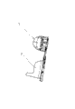
图3为本实用新型折叠后的结构示意图。 Fig. 3 is a structural schematic diagram of the folded utility model.
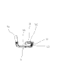
图4为本实用新型中椅背与底座配合的结构示意图,其中椅背处于正常使用状态,第一滑动件卡设在第一槽内。 Fig. 4 is a structural schematic view of the cooperation between the seat back and the base in the present invention, wherein the seat back is in a normal use state, and the first sliding member is clamped in the first groove.
图5为本实用新型中椅背与底座配合的结构示意图,其中第一滑动件被提升,位于第一槽的上方。 Fig. 5 is a structural schematic view of the cooperation between the chair back and the base in the present invention, wherein the first sliding member is lifted and located above the first slot.
图6为本实用新型中椅背与底座配合的结构示意图,其中椅背处于折叠状态。 Fig. 6 is a structural diagram of the cooperation between the chair back and the base in the utility model, wherein the chair back is in a folded state.
图7为本实用新型中椅背与底座配合的结构示意图,椅背处于部分打开状态,且第一滑动件贴靠在底座上。 Fig. 7 is a schematic diagram of the structure of the cooperation between the seat back and the base in the present invention, the seat back is in a partially opened state, and the first sliding member is attached to the base.
图8为本实用新型中椅背与底座配合的结构示意图,椅背处于部分打开状态,且第一滑动件贴靠在底座上。 Fig. 8 is a structural schematic diagram of the cooperation between the chair back and the base in the present invention, the chair back is in a partially opened state, and the first sliding member leans against the base.
图9为头枕的结构示意图,其中护板处于正常使用状态。 Fig. 9 is a structural schematic diagram of the headrest, where the guard plate is in a normal use state.
图10为头枕的结构示意图,其中护板处于正常使用状态,并且第二滑动件位于第三槽外。 Fig. 10 is a structural schematic diagram of the headrest, where the guard plate is in a normal use state, and the second sliding member is located outside the third groove.
图11为头枕的结构示意图,其中一个护板处于折叠状态。 Fig. 11 is a structural schematic diagram of the headrest, one of the guard plates is in a folded state.
图12为头枕的结构示意图,其中二个护板均处于折叠状态。 Fig. 12 is a structural schematic diagram of the headrest, in which the two guard plates are in a folded state.
图13为头枕的结构示意图,其中一个护板处于部分打开状态。 Fig. 13 is a structural schematic diagram of the headrest, one of the shields is in a partially opened state.
图14为椅背与头枕的配合结构示意图,此时第二凸起位于第一凸起上方。 Fig. 14 is a schematic diagram of the cooperation structure of the seat back and the headrest, at this time, the second protrusion is located above the first protrusion.
图15为椅背与头枕的配合结构示意图,此时第二凸起顶靠第一凸起。 Fig. 15 is a schematic diagram of the cooperation structure of the seat back and the headrest, at this time, the second protrusion is against the first protrusion.
图16为椅背与头枕的配合结构示意图,其中头枕处于正常状态。 Fig. 16 is a schematic diagram of the cooperation structure of the seat back and the headrest, wherein the headrest is in a normal state.
图17为椅背与头枕的配合结构示意图,此时第二凸起位于第一凸起下方。 Fig. 17 is a schematic diagram of the cooperation structure of the seat back and the headrest, at this time, the second protrusion is located below the first protrusion.
图18为椅背与头枕的配合结构示意图,其中头枕与椅背处于分离状态。 Fig. 18 is a schematic diagram of the cooperation structure of the seat back and the headrest, wherein the headrest and the seat back are in a separated state.
具体实施方式 Detailed ways
下面结合附图与具体实施方式对本实用新型作进一步详细描述:本实用新型没有特别声明,图4中的左侧即为本实用新型的前端,图4中的右侧即为本实用新型的后端,图4中的上端即为本实用新型的上端,图4中的下端即为本实用新型的下端。 The utility model is further described in detail below in conjunction with the accompanying drawings and specific embodiments: the utility model has no special statement, the left side in Fig. 4 is the front end of the utility model, and the right side in Fig. 4 is the rear of the utility model End, the upper end in Fig. 4 is the upper end of the utility model, and the lower end in Fig. 4 is the lower end of the utility model.
参见图1~图18, 一种车用儿童安全座椅,包括底座1,所述底座1通过铰链2铰接有椅背3,所述铰链2位于椅背3外侧的一端设置有外螺纹,该外螺纹上拧设有旋钮4。需要旋转椅背3时,松开旋钮4,即可使椅背3以铰链2为旋转轴线与底座1相对转动。
Referring to Figures 1 to 18, a child safety seat for a vehicle includes a
所述底座1上开设有第一槽10,所述椅背3的背部设置有第一板17,并且所述第一板17的上端具有一个容纳部21,所述第一板17拼合有第二板19,第一板17和第二板19之间穿设有第一滑动件7。所述第一滑动件7上端设置有第一环形凸起70,一个第一弹性组件9套设在所述第一环形凸起70上。未受力时,所述第一弹性组件9的上端顶靠在所述容纳部21的底部,所述第一弹性组件9的下端顶靠在第一滑动件7的上端。优选的,所述的第一弹性组件9为弹簧。
The
优选的,所述第一滑动件7的下端具有一个弧形面72。设置有弧形面72可以使第一滑动件7顺畅的滑过底座1,并使第一滑动件7卡入第一槽10中。
Preferably, the lower end of the first sliding
所述第一板17上端的容纳部21上开设有第二槽210,所述容纳部21相应于第二槽210的侧壁上具有弹性片211,所述弹性片211具有第一凸起212,所述弹性片211上还设置有便于手握持的凸片213。
The
一个头枕5的下端设置有连接板6,所述连接板6穿设在第二槽210内,所述连接板6上设置有第二凸起60。所述第一凸起212的上端具有一个锥形面2120。锥形面2120的作用是便于第一凸起212滑过第二凸起60。
The lower end of a
上文所述的头枕5包括本体50,所述本体50两侧设置有护板51,所述护板51与本体50之间设置有一个可使护板51侧壁折叠于本体50侧壁的折叠机构。
The
所述折叠机构包括设置在所述本体50与护板51之间的铰接机构,以及设置在护板51上的第三槽52,所述本体50上设置有可相对于本体50滑移的第二滑动件11,所述第二滑动件11的端部具有一个弧形面110。
The folding mechanism includes a hinge mechanism arranged between the
所述本体50上设置有第二环形凸起500,一个第二弹性组件13套设在所述第二环形凸起500上。所述第二滑动件11的一端顶靠在所述第二弹性组件13上。优选的,所述第二弹性组件13为弹簧。
The
将头枕5安装到椅背3时,将连接板6穿入至第二槽210内,连接板6上设置的第二凸起60接触第一凸起212,并在第一凸起212的锥形面2120的作用下使弹性片211向椅背3的背部撑开,并最终使第二凸起60滑过第一凸起212。从而使头枕5安装于椅背3上。
When the
需要使头枕5与椅背3分离时,往上提升头枕5,当第二凸起60接近第一凸起212时(由于第一凸起212的阻挡作用,第二凸起60无法滑过第一凸起212,这样不仅能使产品更安全,还能有效的防止误操作,即一不小心将头枕5拔离出椅背3,影响产品使用。),扳动凸片213,从而使弹性片211向椅背3的背部撑开,使第一凸起212不再阻挡第二凸起60,从而使头枕5的连接板6滑移出容纳部21,从而实现头枕5与椅背3的分离。
When it is necessary to separate the
当需要运输时,首先使头枕5从椅背处拆下,然后将椅背3折叠于底座1,操作方法如下:提升第一滑动件7,使第一滑动件7的下端离开第一槽10(见图5),然后使椅背3以铰链2为旋转轴线与底座1呈逆时针相对转动,并最终折叠至图3所示状态。之后将头枕5上的护板51侧壁折叠于本体50侧壁上,操作方法如下:拉动第二滑动件11,使第二滑动件11的端部离开第三槽52(见图10),然后将护板51侧壁折叠于本体50侧壁上(见图11和图12)。之后将折叠好后的头枕5塞在已折叠的椅背和底座之间。
When it needs to be transported, first remove the
当需要使用时,首先打开椅背3,操作方法如下,用力提升椅背3,使椅背3以铰链2为旋转轴线与底座1呈顺时针相对转动,第一滑动件7的弧形面滑过底座1,并在第一弹性组件9作用下卡入第一槽10中。从而实现椅背3处于正常使用状态。然后打开头枕5,操作方法如下,转动护板51,使第二滑动件11的弧形面110滑过本体50,并在第二弹性组件13的作用下卡入第三槽52中,从而使头枕5处于正常使用状态。
When it needs to be used, first open the seat back 3, the operation method is as follows, forcefully lift the seat back 3, so that the seat back 3 rotates clockwise with the hinge 2 as the axis of rotation and the
Claims (7)
Priority Applications (1)
| Application Number | Priority Date | Filing Date | Title |
|---|---|---|---|
| CN 201220134722 CN202686016U (en) | 2012-04-01 | 2012-04-01 | Child safety seat for car |
Applications Claiming Priority (1)
| Application Number | Priority Date | Filing Date | Title |
|---|---|---|---|
| CN 201220134722 CN202686016U (en) | 2012-04-01 | 2012-04-01 | Child safety seat for car |
Publications (1)
| Publication Number | Publication Date |
|---|---|
| CN202686016U true CN202686016U (en) | 2013-01-23 |
Family
ID=47541677
Family Applications (1)
| Application Number | Title | Priority Date | Filing Date |
|---|---|---|---|
| CN 201220134722 Expired - Fee Related CN202686016U (en) | 2012-04-01 | 2012-04-01 | Child safety seat for car |
Country Status (1)
| Country | Link |
|---|---|
| CN (1) | CN202686016U (en) |
Cited By (5)
| Publication number | Priority date | Publication date | Assignee | Title |
|---|---|---|---|---|
| CN104210392A (en) * | 2014-09-19 | 2014-12-17 | 杭州大器婴童用品有限公司 | Child safety seat |
| CN106985937A (en) * | 2017-04-27 | 2017-07-28 | 江门申强塑料机械有限公司 | A kind of child safety seat |
| WO2017148310A1 (en) * | 2016-03-04 | 2017-09-08 | 李述章 | Portable foldable child safety seat |
| WO2017173711A1 (en) * | 2016-04-07 | 2017-10-12 | 上海沃雨电子科技有限公司 | Foldable manual child safety seat |
| CN113787944A (en) * | 2021-10-29 | 2021-12-14 | 宁波宝贝第一母婴用品有限公司 | Child safety seat |
-
2012
- 2012-04-01 CN CN 201220134722 patent/CN202686016U/en not_active Expired - Fee Related
Cited By (6)
| Publication number | Priority date | Publication date | Assignee | Title |
|---|---|---|---|---|
| CN104210392A (en) * | 2014-09-19 | 2014-12-17 | 杭州大器婴童用品有限公司 | Child safety seat |
| WO2017148310A1 (en) * | 2016-03-04 | 2017-09-08 | 李述章 | Portable foldable child safety seat |
| WO2017173711A1 (en) * | 2016-04-07 | 2017-10-12 | 上海沃雨电子科技有限公司 | Foldable manual child safety seat |
| CN106985937A (en) * | 2017-04-27 | 2017-07-28 | 江门申强塑料机械有限公司 | A kind of child safety seat |
| CN113787944A (en) * | 2021-10-29 | 2021-12-14 | 宁波宝贝第一母婴用品有限公司 | Child safety seat |
| CN113787944B (en) * | 2021-10-29 | 2023-01-24 | 宁波宝贝第一母婴用品有限公司 | Child safety seat |
Similar Documents
| Publication | Publication Date | Title |
|---|---|---|
| CN202686016U (en) | Child safety seat for car | |
| CN101508255B (en) | Armrest devices and child seats with armrest devices | |
| EP3495196B1 (en) | Child car safety seat | |
| CN201665233U (en) | Buckling mechanism of baby safety seat | |
| CN202098305U (en) | Automobile chair for children | |
| CN116080495A (en) | Automobile safety seat | |
| CN107128220A (en) | Automobile seat for child | |
| CN202743145U (en) | Car front seat storage box device | |
| CN104002737B (en) | Automobile armrest box | |
| CN202573879U (en) | Child safety seat headrest for vehicle | |
| CN218750441U (en) | Automobile seat cushion and automobile | |
| CN202863190U (en) | Integrated automobile child safety seat | |
| CN202588542U (en) | Lock catch for restraint system | |
| CN202966019U (en) | Automotive child safety seat having adjustable back angle | |
| CN203110963U (en) | Substrate for safe upholder of children with locking mechanism | |
| CN111873869B (en) | Child car safety seat | |
| WO2014101260A1 (en) | Multifunctional safety device for automobile seat and automobile safety seat | |
| CN203698005U (en) | Automotive child safety seat | |
| CN202782762U (en) | Vehicle-mounted seat | |
| CN202357913U (en) | Kid targeted cart seat main body applied safe overturning mechanism | |
| KR101035513B1 (en) | Car Seats | |
| CN201953151U (en) | Inside door-handle for vehicle | |
| CN202063037U (en) | Child safety seat for vehicle | |
| CN202686024U (en) | Automotive child safety seat | |
| CN202448798U (en) | Children heightened seat cushion for vehicle |
Legal Events
| Date | Code | Title | Description |
|---|---|---|---|
| C14 | Grant of patent or utility model | ||
| GR01 | Patent grant | ||
| CF01 | Termination of patent right due to non-payment of annual fee | ||
| CF01 | Termination of patent right due to non-payment of annual fee |
Granted publication date: 20130123 Termination date: 20210401 |