CN202052290U - Improved racket frame structure - Google Patents
Improved racket frame structure Download PDFInfo
- Publication number
- CN202052290U CN202052290U CN201120133323XU CN201120133323U CN202052290U CN 202052290 U CN202052290 U CN 202052290U CN 201120133323X U CN201120133323X U CN 201120133323XU CN 201120133323 U CN201120133323 U CN 201120133323U CN 202052290 U CN202052290 U CN 202052290U
- Authority
- CN
- China
- Prior art keywords
- ribs
- frame
- head frame
- reinforcing ribs
- racket
- Prior art date
- Legal status (The legal status is an assumption and is not a legal conclusion. Google has not performed a legal analysis and makes no representation as to the accuracy of the status listed.)
- Expired - Fee Related
Links
- 239000000945 filler Substances 0.000 claims abstract description 20
- 239000000463 material Substances 0.000 claims abstract description 5
- OKTJSMMVPCPJKN-UHFFFAOYSA-N Carbon Chemical compound [C] OKTJSMMVPCPJKN-UHFFFAOYSA-N 0.000 claims 1
- 229910052799 carbon Inorganic materials 0.000 claims 1
- 239000000835 fiber Substances 0.000 claims 1
- 230000003014 reinforcing effect Effects 0.000 abstract description 90
- 229920000049 Carbon (fiber) Polymers 0.000 abstract description 19
- 239000004917 carbon fiber Substances 0.000 abstract description 19
- VNWKTOKETHGBQD-UHFFFAOYSA-N methane Chemical compound C VNWKTOKETHGBQD-UHFFFAOYSA-N 0.000 abstract description 19
- 238000000034 method Methods 0.000 abstract description 7
- 230000008569 process Effects 0.000 abstract description 2
- 238000010276 construction Methods 0.000 abstract 1
- 230000002349 favourable effect Effects 0.000 abstract 1
- 238000010586 diagram Methods 0.000 description 6
- 230000002787 reinforcement Effects 0.000 description 4
- 230000006835 compression Effects 0.000 description 3
- 238000007906 compression Methods 0.000 description 3
- 238000000465 moulding Methods 0.000 description 3
- 230000007812 deficiency Effects 0.000 description 2
- 238000005516 engineering process Methods 0.000 description 2
- 238000010438 heat treatment Methods 0.000 description 2
- 238000004519 manufacturing process Methods 0.000 description 2
- 238000012986 modification Methods 0.000 description 2
- 230000004048 modification Effects 0.000 description 2
- 230000009286 beneficial effect Effects 0.000 description 1
- 238000013329 compounding Methods 0.000 description 1
- 230000000694 effects Effects 0.000 description 1
- 230000004044 response Effects 0.000 description 1
Images


Classifications
-
- A—HUMAN NECESSITIES
- A63—SPORTS; GAMES; AMUSEMENTS
- A63B—APPARATUS FOR PHYSICAL TRAINING, GYMNASTICS, SWIMMING, CLIMBING, OR FENCING; BALL GAMES; TRAINING EQUIPMENT
- A63B49/00—Stringed rackets, e.g. for tennis
- A63B49/02—Frames
- A63B49/10—Frames made of non-metallic materials, other than wood
- A63B49/11—Frames made of non-metallic materials, other than wood with inflatable tubes, e.g. inflatable during fabrication
-
- A—HUMAN NECESSITIES
- A63—SPORTS; GAMES; AMUSEMENTS
- A63B—APPARATUS FOR PHYSICAL TRAINING, GYMNASTICS, SWIMMING, CLIMBING, OR FENCING; BALL GAMES; TRAINING EQUIPMENT
- A63B53/00—Golf clubs
- A63B53/10—Non-metallic shafts
-
- A—HUMAN NECESSITIES
- A63—SPORTS; GAMES; AMUSEMENTS
- A63B—APPARATUS FOR PHYSICAL TRAINING, GYMNASTICS, SWIMMING, CLIMBING, OR FENCING; BALL GAMES; TRAINING EQUIPMENT
- A63B49/00—Stringed rackets, e.g. for tennis
- A63B49/02—Frames
- A63B49/03—Frames characterised by throat sections, i.e. sections or elements between the head and the shaft
- A63B2049/0325—Frames characterised by throat sections, i.e. sections or elements between the head and the shaft with two legs having mutually different constructions
-
- A—HUMAN NECESSITIES
- A63—SPORTS; GAMES; AMUSEMENTS
- A63B—APPARATUS FOR PHYSICAL TRAINING, GYMNASTICS, SWIMMING, CLIMBING, OR FENCING; BALL GAMES; TRAINING EQUIPMENT
- A63B2209/00—Characteristics of used materials
- A63B2209/02—Characteristics of used materials with reinforcing fibres, e.g. carbon, polyamide fibres
Landscapes
- Health & Medical Sciences (AREA)
- General Health & Medical Sciences (AREA)
- Physical Education & Sports Medicine (AREA)
- Chemical & Material Sciences (AREA)
- Engineering & Computer Science (AREA)
- Materials Engineering (AREA)
- Casting Or Compression Moulding Of Plastics Or The Like (AREA)
- Laminated Bodies (AREA)
Abstract
Description
技术领域 technical field
本实用新型涉及体育运动器材之球拍领域技术,尤其是指一种由碳纤维材料制成的网球拍框架的改进结构。 The utility model relates to the technology in the field of sports equipment rackets, in particular to an improved structure of a tennis racket frame made of carbon fiber materials. the
背景技术 Background technique
众所周知,如图1所示,人们所熟知的网球拍主要由头框10、三角喉部20和手柄30三部分组成。在网球拍领域,碳纤维质网球拍以有较轻的重量占了主流市场,然而由于碳纤维球拍的抗冲击性和强度差,球拍受到撞击时易损坏,易产生变形,造成球拍的使用寿命不长。
As everyone knows, as shown in FIG. 1 , the well-known tennis racket is mainly composed of three parts: a
针对于此,市面上有出现一些于碳纤球拍框架空心管内设置加强肋以改善球拍的强度,这种球拍加工时,由两个碳纤维管堆叠复合而成,二个对称的相邻管壁固化形成加强肋,由于传统的碳纤球拍框架是以吹气的方式使空心管膨胀贴紧模具,为了让气体可以均匀地分布在球拍框架的各个部位,整个球拍的头框、三角喉部之截面上所形成的加强肋均方向相同、数量相等,其中由于手柄是由三角喉部左右两碳纤管延伸复合而成且二者之间的空心管是相通的,因此,手柄截面之加强肋是三角喉部两碳纤管的加强肋之和。 In response to this, there are some carbon fiber racket frame hollow tubes on the market that are provided with reinforcing ribs to improve the strength of the racket. When this racket is processed, it is composed of two carbon fiber tubes stacked and composited, and two symmetrical adjacent tube walls are solidified to form Reinforcing ribs, because the traditional carbon fiber racket frame is blown to make the hollow tube expand and stick to the mold, in order to allow the gas to be evenly distributed in all parts of the racket frame, the head frame of the entire racket and the section of the triangular throat The reinforcing ribs formed have the same direction and the same number. Since the handle is formed by extending and compounding two carbon fiber tubes on the left and right sides of the triangular throat and the hollow tubes between the two are connected, the reinforcing ribs of the handle section are the triangular throat The sum of the ribs of the two carbon fiber tubes. the
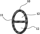
如图2、图3和图4所示,其显示了现有产品的一种结构,其头框10和三角喉部20之截面的加强肋11、12的方向与击球平面垂直,其数量均为一条,该加强肋11、12将头框和三角喉部之截面一分为二个左右并列的空心腔12、22,其中,手柄30之截面的加强肋31之方向如同上述的头框10和三角喉部20,而加强肋31的数量为三条,将手柄30之截面一分为四个左右紧密并列的空心腔32,各空心腔内没有膨胀填充物。
As shown in Fig. 2, Fig. 3 and Fig. 4, it has shown a kind of structure of existing product, and the direction of reinforcing
再看图5、图6和图7所示,其显示了现有产品的另一种结构,其加强肋11、21、31的方向与击球平面平行,其中头框10和三角喉部20之截面的加强肋11、12为一条,将头框10和三角喉部20之截面一分为二个上下对称的空心腔12、22,而手柄30之截面的加强肋31为三条,将手柄30之截面一分为四个上下紧密堆叠的空心腔32。
See Fig. 5, Fig. 6 and shown in Fig. 7 again, it has shown another kind of structure of existing product, and the direction of its reinforcing
此两种结构虽具有改善球拍之抗冲击、抗压性能的效果,但由于其加工工艺的限制,整个球拍框架的头框和三角喉部之截面上所形成的加强肋必须方向相同、数量相等,同时手柄之截面的加强肋也随之而被确定,也就意味着只要确定了头框、三角喉部或手柄三个部件中的其中一个部件之截面上加强肋的方向和数量,其它部件之截面的加强肋的方向和数量就随之确定。然而,球拍使用者根据个人习惯有时喜欢头框截面之加强肋的设置方向是平行于击球平面,而三角喉部截面之加强肋的方向是垂直于击球平面,并且要求头框截面之加强肋的数量与三角喉部截面之加强肋的数量不同,这种结构对于上述现有技术是无法做到的,如此,就无法根据客户的需求任意的改变加强肋的方向和数量,不利于市场竞争。 Although these two structures have the effect of improving the impact resistance and compression resistance of the racket, due to the limitation of their processing technology, the reinforcing ribs formed on the cross section of the head frame and triangular throat of the entire racket frame must have the same direction and equal number At the same time, the reinforcement ribs of the section of the handle are also determined, which means that as long as the direction and number of reinforcement ribs on the section of one of the three parts of the head frame, triangular throat or handle are determined, the other parts The direction and number of ribs in the cross-section are then determined. However, according to personal habits, racket users sometimes prefer that the direction of the reinforcing ribs of the head frame section is parallel to the hitting plane, while the direction of the reinforcing ribs of the triangular throat section is perpendicular to the hitting plane, and requires reinforcement of the head frame section. The number of ribs is different from the number of reinforcing ribs in the triangular throat section. This structure cannot be achieved for the above-mentioned prior art. In this way, the direction and number of reinforcing ribs cannot be changed arbitrarily according to the needs of customers, which is not conducive to the market. compete. the
因此,如何使一种球拍可以根据不同需求而分别在头框、三角喉部和手柄设置至少在方向或者数量不同的加强肋,是从事此行业的技术人员所亟待研究改善的方向所在。 Therefore, how to provide a racket with reinforcing ribs that are at least different in direction or number on the head frame, triangular throat and handle according to different requirements is the direction that technicians engaged in this industry need to study and improve urgently. the
实用新型内容 Utility model content
本实用新型针对现有技术存在之缺失,其主要目的是提供一种改进的网球拍框架结构,其头框所设的加强肋与三角喉部的加强肋在数量或方向不同,从而满足不同使用者对球拍不同部位之强度、重量和抗振性能的要求,解决了现有技术之不足。 The utility model aims at the deficiencies of the prior art, and its main purpose is to provide an improved tennis racket frame structure. The reinforcing ribs on the head frame and the reinforcing ribs on the triangular throat are different in number or direction, so as to satisfy different uses. The requirements of the player on the strength, weight and anti-vibration performance of different parts of the racket solve the deficiencies in the prior art. the
为实现上述目的,本实用新型采用如下之技术方案: In order to achieve the above object, the utility model adopts the following technical solutions:
一种改进的网球拍框架结构,包括有由碳纤材料制成的头框、三角喉部和手柄,所述头框和三角喉部里面设有加强肋,该头框或三角喉部中至少两个局部位置的加强肋在方向或者数量不同,各加强肋分隔形成的空心腔内都置有膨胀填充物。 An improved tennis racket frame structure, including a head frame made of carbon fiber material, a triangular throat and a handle, the head frame and the triangular throat are provided with reinforcing ribs, and at least two of the head frame or the triangular throat are The reinforcing ribs at each local position are different in direction or quantity, and the hollow cavities formed by each reinforcing rib are filled with expansion fillers.
作为一种优选方案,所述三角喉部中的加强肋与头框中的加强肋数量相等,方向不同。 As a preferred solution, the number of reinforcing ribs in the triangular throat and the reinforcing ribs in the head frame are equal but in different directions. the
作为一种优选方案,所述头框的加强肋有两条,均平行于击球平面设置,该两条加强肋将头框分为上中下三个空心腔;所述三角喉部的加强肋有两条,均垂直于击球平面设置,该两条加强肋将三角喉部分为左中右三个空心腔。 As a preferred solution, there are two reinforcing ribs of the head frame, both of which are arranged parallel to the hitting plane, and the two reinforcing ribs divide the head frame into three hollow cavities, upper, middle and lower; There are two ribs, both of which are arranged perpendicular to the hitting plane. The two reinforcing ribs divide the triangular throat into three hollow cavities, left, middle and right. the
作为一种优选方案,所述三角喉部中的加强肋与头框中的加强肋数量不等,方向相同。 As a preferred solution, the number of reinforcing ribs in the triangular throat and the reinforcing ribs in the head frame are different, and the directions are the same. the
作为一种优选方案,所述头框的加强肋有一条,该加强肋平行于击球平面设置,将头框分为上下对称的两个空心腔;所述三角喉部的加强肋有三条,均平行于击球平面设置,该三条加强肋将三角喉部分为由下至上顺序排列的三个空心腔。 As a preferred solution, there is one reinforcing rib of the head frame, which is arranged parallel to the hitting plane, and divides the head frame into two symmetrical hollow cavities; the triangular throat has three reinforcing ribs, They are all arranged parallel to the hitting plane, and the three reinforcing ribs divide the triangular throat into three hollow cavities arranged in sequence from bottom to top. the
作为一种优选方案,所述三角喉部中的加强肋与头框中的加强肋数量不等,方向不同。 As a preferred solution, the number of reinforcing ribs in the triangular throat and the reinforcing ribs in the head frame are different, and the directions are different. the
作为一种优选方案,所述头框的加强肋有三条,该加强肋垂直于击球平面设置,将头框分为由左到右顺序排列的四个空心腔;所述三角喉部的加强肋有一条,该加强肋平行于击球平面设置,将三角喉部分为上下对称的两个空心腔。 As a preferred solution, there are three reinforcing ribs of the head frame, which are arranged perpendicular to the hitting plane, and divide the head frame into four hollow cavities sequentially arranged from left to right; the reinforcing ribs of the triangular throat There is one rib, the reinforcing rib is arranged parallel to the hitting plane, and divides the triangular throat into two symmetrical hollow cavities up and down. the
作为一种优选方案,所述头框上部的加强肋和头框下部的加强肋至少在方向或者数量上不同。 As a preferred solution, the reinforcing ribs on the upper part of the head frame and the reinforcing ribs on the lower part of the head frame are different at least in direction or quantity. the
作为一种优选方案,所述头框上部的加强肋有一条,该加强肋垂直于击球平面设置,将头框上部分为左右对称的两个空心腔;所述头框下部的加强肋有两条,该加强肋平行于击球平面设置,将头框下部分为由下至上顺序排列的三个空心腔。 As a preferred solution, there is one reinforcing rib on the upper part of the head frame, which is arranged perpendicular to the hitting plane, and divides the upper part of the head frame into two symmetrical hollow cavities; the reinforcing rib on the lower part of the head frame has Two reinforcement ribs are arranged parallel to the hitting plane, dividing the lower part of the head frame into three hollow cavities arranged in sequence from bottom to top. the
作为一种优选方案,所述头框上部的加强肋、头框中部的加强肋和头框下部的加强肋至少在方向或者数量上不同。 As a preferred solution, the reinforcing ribs on the upper part of the head frame, the reinforcing ribs on the middle part of the head frame and the reinforcing ribs on the lower part of the head frame are different at least in direction or quantity. the
本实用新型与现有技术相比具有明显的优点和有益效果,其主要系使该头框或三角喉部中至少两个局部位置的加强肋在方向或者数量不同,并于各加强肋分隔出的空心腔都置有肿胀填充物。籍此,一方面可以根据客户对球拍硬度、重量、抗压性和抗振性等的不同需求而对球拍不同部分的结构做量身定制,使球拍框架的性能达到最大化,大大增加产品的吸引性,非常有利于现代社会激烈的市场竞争。另外,球拍框架内部的空心腔中置入有膨胀填充物,在加热固化成型时,直接利用膨胀填充物受热膨胀时的膨胀张力来作为空心管的内压力,使空心管可紧贴于模具的内壁面上,达到不同方向、不同数量加强肋的成型目的。此种做法完全有别于传统之充入压缩空气作为其内压力的做法,而且可根本性避免漏气和局部受压不平衡的问题,具有较佳的制作效率和品质良率。 Compared with the prior art, the utility model has obvious advantages and beneficial effects. It mainly makes the reinforcing ribs in at least two local positions in the head frame or the triangular throat different in direction or quantity, and separates them from each reinforcing rib. All hollow cavities are filled with tumescent fillers. In this way, on the one hand, the structure of different parts of the racket can be customized according to the different needs of customers for the hardness, weight, compression resistance and vibration resistance of the racket, so as to maximize the performance of the racket frame and greatly increase the product's Attractiveness is very conducive to the fierce market competition in modern society. In addition, an expansion filler is placed in the hollow cavity inside the racket frame. When heating and curing molding, the expansion tension of the expansion filler when heated and expanded is used as the internal pressure of the hollow tube, so that the hollow tube can be closely attached to the mold. On the inner wall surface, the forming purpose of different directions and different numbers of reinforcing ribs can be achieved. This method is completely different from the traditional method of filling compressed air as the internal pressure, and can fundamentally avoid the problems of air leakage and local pressure imbalance, and has better production efficiency and quality yield. the
为更清楚地阐述本实用新型的结构特征和功效,下面结合附图与具体实施例来对本实用新型进行详细说明。 In order to illustrate the structural features and functions of the utility model more clearly, the utility model will be described in detail below in conjunction with the accompanying drawings and specific embodiments. the
附图说明 Description of drawings
图1是现有技术中常见之网球拍的正视图; Fig. 1 is the front view of common tennis racket in the prior art;
图2是图1中M-M位置之截面的其中一种结构示意图; Fig. 2 is one of the structural schematic diagrams of the section of the M-M position in Fig. 1;
图3是图1中N-N位置之截面的其中一种结构示意图; Fig. 3 is one of the structural schematic diagrams of the section of the N-N position in Fig. 1;
图4是图1中P-P位置之截面的其中一种结构示意图; Fig. 4 is one of the structural schematic diagrams of the section of the P-P position in Fig. 1;
图5 是图1中M-M位置之截面的另一种结构示意图; Fig. 5 is another kind of structural representation of the section of M-M position in Fig. 1;
图6是图3中N-N位置之截面的另一种结构示意图; Fig. 6 is another kind of structural representation of the section of N-N position in Fig. 3;
图7是图3中P-P位置之截面的另一种结构示意图; Fig. 7 is another kind of structural representation of the section of P-P position among Fig. 3;
图8是本实用新型实施例之球拍框架整体结构示意图; Fig. 8 is a schematic diagram of the overall structure of the racket frame of the embodiment of the present invention;
图9是本实用新型之第一种实施例于图8中A-A处之截面示意图; Fig. 9 is a schematic cross-sectional view of the first embodiment of the present invention at A-A in Fig. 8;
图10是本实用新型之第一种实施例于图8中B-B处之截面示意图; Fig. 10 is a schematic cross-sectional view of the first embodiment of the present utility model at the B-B place in Fig. 8;
图11是本实用新型之第一种实施例于图8中C-C处之截面示意图; Fig. 11 is a schematic cross-sectional view at C-C in Fig. 8 of the first embodiment of the present utility model;
图12是本实用新型之第二种实施例于图8中A-A处之截面示意图; Fig. 12 is a schematic cross-sectional view of the second embodiment of the present invention at A-A in Fig. 8;
图13是本实用新型之第二种实施例于图8中B-B处之截面示意图; Fig. 13 is a schematic cross-sectional view of the second embodiment of the present invention at B-B in Fig. 8;
图14是本实用新型之第二种实施例于图8中C-C处之截面示意图; Fig. 14 is a schematic cross-sectional view of the second embodiment of the present invention at C-C in Fig. 8;
图15是本实用新型之第三种实施例于图8中A-A处之截面示意图; Fig. 15 is a schematic cross-sectional view of a third embodiment of the present invention at A-A in Fig. 8;
图16是本实用新型之第三种实施例于图8中B-B处之截面示意图; Fig. 16 is a schematic cross-sectional view of a third embodiment of the present invention at B-B in Fig. 8;
图17是本实用新型之第三种实施例于图8中C-C处之截面示意图; Fig. 17 is a schematic cross-sectional view of a third embodiment of the present invention at C-C in Fig. 8;
图18是本实用新型第四种实施例之球拍框架整体结构示意图; Fig. 18 is a schematic diagram of the overall structure of the racket frame of the fourth embodiment of the present invention;
图19是本实用新型之第四种实施例于图18中T-T处之截面示意图; Fig. 19 is a schematic cross-sectional view of a fourth embodiment of the present invention at T-T in Fig. 18;
图20是本实用新型之第四种实施例于图18中K-K处之截面示意图; Fig. 20 is a schematic cross-sectional view of a fourth embodiment of the present invention at K-K in Fig. 18;
图21是本实用新型第五种实施例之球拍框架整体结构示意图; Fig. 21 is a schematic diagram of the overall structure of the racket frame of the fifth embodiment of the present invention;
图22是本实用新型之第五种实施例于图21中G-G处之截面示意图; Fig. 22 is a schematic cross-sectional view of the fifth embodiment of the present invention at G-G in Fig. 21;
图23是本实用新型之第五种实施例于图21中H-H处之截面示意图; Fig. 23 is a schematic cross-sectional view of the fifth embodiment of the present invention at the H-H place in Fig. 21;
图24是本实用新型之第五种实施例于图21中I-I处之截面示意图。 Fig. 24 is a schematic cross-sectional view at I-I in Fig. 21 of the fifth embodiment of the present invention.
附图标识说明: Explanation of the accompanying drawings:
100、拍框基体 10、头框
100.
20、三角喉部 30、手柄
20.
40、膨胀填充物 11、21、31、加强肋
40.
12、22、32、空心腔。 12, 22, 32, hollow cavity.
具体实施方式:Detailed ways:
首先,请参照图8至图11所示,其显示出了本实用新型之球拍框架第一种实施例的具体结构,该球拍框架100由碳纤材料制成,其包括有头框10、三角喉部20和手柄30。
First, please refer to Figures 8 to 11, which show the specific structure of the first embodiment of the racket frame of the present invention, the
具体而言,所述头框10弯成大致封闭的椭圆状,头框10周边开设一组线孔,网线纵横穿设在线孔中构成击球平面,头框10下端与三角喉部20的上端连接,而三角喉部20的下端与所述手柄30相接。
Specifically, the
承上,请配合图9和图10所示,所述头框10、三角喉部20和手柄里面设置有加强肋11、21、31,其中,头框和三角喉部中的加强肋11、21方向不同、数量相等。本实施例中,头框10里面所设的加强肋11有两条,均平行于击球平面设置,但头框中的加强肋不限于两条,亦可以少于两条或多于两条。该头框中的两条加强肋11将头框分为上中下分布的三个空心腔12,并于每个空心腔12中设有膨胀填充物40。三角喉部20的加强肋21也有两条,均垂直于击球平面设置,但三角喉部20之加强肋21也不限于两条,亦可以多于两条或少于两条。该三角喉部中的两条加强肋21将三角喉部20分为左中右分布的三个空心腔22,同样于各个空心腔22中也设有膨胀填充物40。手柄30里面所设的加强肋有两条,均平行于击球平面设置,该手柄中的两条加强肋将手柄隔开为上中下三个空心腔,各个空心腔中32也置有膨胀填充物40。
As shown in Figure 9 and Figure 10, the
图9到图11的球拍框架结构加工成型的过程中,先由三条置入膨胀填充物40的碳纤空心管堆叠在一起用于组合成头框10的内部结构,再另外用三条置入膨胀填充物40的碳纤空心管组合成三角喉部20的内部结构,而手柄也是以用三条置入膨胀填充物40的碳纤管堆在一起的方式组合而成,最后以一块碳纤布将头框10、三角喉部20和手柄30的碳纤空心管包覆在内,置入球拍模具中加热,此时碳纤空心管内的膨胀填充物40受热膨胀,从内部形成内压力将碳纤空心管胀起紧贴于模具的内壁面上定型,各相邻的碳纤空心管的相邻管壁固化形成加强肋11、21、31。
During the processing and molding process of the racket frame structure shown in Figures 9 to 11, three carbon fiber hollow tubes inserted into the
请参照图8以及图12至图14所示,其显示出了本实用新型之球拍框架第二种实施例的具体结构,本实施例与第一实施例基本相同,其不同之处在于所述的头框10、三角喉部20之截面内设有的加强肋11、21方向相同、数量不等。本实施例中,头框10里面的加强肋11有一条,其平行于击球平面设置,该头框中的加强肋11将头框10分为上下对称的两个空心腔12。三角喉部20之加强肋21有三条,均平行于击球平面设置,该三条加强肋21将三角喉部20之外管分为由下至上顺序排列的四个空心腔22。手柄30的加强肋31有两条,一条平行于击球平面设置,另一条垂直于击球平面设置,该两条垂直相交在一起的加强肋32使手柄30之隔开四个空心腔,四个空腔腔形如一田字形。
Please refer to Figure 8 and Figure 12 to Figure 14, which shows the specific structure of the second embodiment of the racket frame of the present invention, this embodiment is basically the same as the first embodiment, the difference lies in the
请参照图8以及图15至图17所示,其显示出了本实用新型之球拍框架第三种实施例的具体结构,本实施例与第一实施例基本相同,其不同之处在于所述的头框10、三角喉部20之截面内设有的加强肋11、21方向不同、数量不等。本实施例中头框10的加强肋11有三条,均垂直于击球平机设置,该加强肋11将头框10分为由左至右顺序排列的四个空心腔12。三角喉部20的加强肋21有一条,其平行于击球平面设置,该加强肋21将三角喉部20分为上下对称的两个空心腔22。手柄30之加强肋31有三条,均垂直于击球平面设置,该加强肋31将手柄30分为由左至右顺序排列的四个空心腔32。
Please refer to Figure 8 and Figures 15 to 17, which show the specific structure of the third embodiment of the racket frame of the present invention, this embodiment is basically the same as the first embodiment, the difference lies in the
请参照图18至图20所示,其显示出了本实用新型之球拍框架第四种实施例的具体结构,本实施例与第一实施例基本相同,其不同之处在于所述头框上部的加强肋和头框下部的加强肋至少在方向或者数量上不同。在本实施例中,头框上部的加强肋有一条,该加强肋垂直于击球平面设置,将头框上部分为左右对称的两个空心腔;所述头框下部的加强肋有两条,该加强肋平行于击球平面设置,将头框下部分为由下至上顺序排列的三个空心腔。 Please refer to Fig. 18 to Fig. 20, which shows the specific structure of the fourth embodiment of the racket frame of the present invention, this embodiment is basically the same as the first embodiment, the difference lies in the upper part of the head frame The reinforcing ribs of the head frame and the reinforcing ribs of the lower part of the head frame are at least different in direction or quantity. In this embodiment, there is one reinforcing rib on the upper part of the head frame, which is arranged perpendicular to the hitting plane, and the upper part of the head frame is divided into two symmetrical hollow cavities; the reinforcing rib on the lower part of the head frame has two , the reinforcing rib is arranged parallel to the hitting plane, and the lower part of the head frame is divided into three hollow cavities arranged in sequence from bottom to top. the
请参照图21至图24所示,其显示出了本实用新型之球拍框架第五种实施例的具体结构,本实施例与第一实施例基本相同,其不同之处在于所述头框上部的加强肋、头框中部的加强肋和头框下部的加强肋至少在方向或者数量上不同。在本实施例中,头框上部的加强肋有一条,该加强肋平行于击球平面设置,将头框上部分为上下对称的两个空心腔;所述头框中部的加强肋有三条,分别垂直于击球平面设置,将头框中部分为从左到右顺序排列的四个空心腔;所述头框下部的加强肋有两条,该加强肋平行于击球平面设置,将头框下部分为由下至上顺序排列的三个空心腔。 Please refer to Figure 21 to Figure 24, which shows the specific structure of the fifth embodiment of the racket frame of the present invention, this embodiment is basically the same as the first embodiment, the difference lies in the upper part of the head frame The reinforcing ribs in the head frame, the reinforcing ribs in the middle of the head frame and the reinforcing ribs in the lower part of the head frame are at least different in direction or number. In this embodiment, there is one reinforcing rib on the upper part of the head frame, which is arranged parallel to the hitting plane, and divides the upper part of the head frame into two symmetrical hollow cavities; there are three reinforcing ribs on the middle part of the head frame, Set perpendicular to the hitting plane respectively, divide the middle part of the head frame into four hollow cavities arranged in sequence from left to right; there are two reinforcing ribs at the bottom of the head frame, the reinforcing ribs are arranged parallel to the hitting plane, and the head The lower part of the frame is three hollow cavities arranged sequentially from bottom to top. the
综合而言,本实用新型的设计重点在于,其主要系于球拍框架的头框、三角喉部和手柄中设置有加强肋,其中该头框或三角喉部中至少两个局部位置的加强肋在方向或者数量不同,并于各加强肋所分隔出的空心腔内置有膨胀填充物。籍此,一方面可以根据客户对球拍硬度、重量、抗压性和抗振性等的不同需求而对球拍不同部分的结构做量身定制,使球拍框架的性能达到最大化,大大增加产品的吸引性,非常有利于现代社会激烈的市场竞争。另外,球拍框架内部的空心腔中置入有膨胀填充物,在加热固化成型时,直接利用膨胀填充物受热膨胀时的膨胀张力来作为空心管的内压力,使空心管可紧贴于模具的内壁面上,达到不同方向、不同数量加强肋的成型目的。此种做法完全有别于传统之充入压缩空气作为其内压力的做法,而且可根本性避免漏气和局部受压不平衡的问题,具有较佳的制作效率和品质良率。 In general, the key point of the design of this utility model is that it is mainly tied to the fact that the head frame, triangular throat and handle of the racket frame are provided with reinforcing ribs, wherein the reinforcing ribs at least two local positions in the head frame or triangular throat The directions or numbers are different, and expansion fillers are built in the hollow cavities separated by the reinforcing ribs. In this way, on the one hand, the structure of different parts of the racket can be customized according to the different needs of customers for the hardness, weight, compression resistance and vibration resistance of the racket, so as to maximize the performance of the racket frame and greatly increase the product's Attractiveness is very conducive to the fierce market competition in modern society. In addition, an expansion filler is placed in the hollow cavity inside the racket frame. When heating and curing molding, the expansion tension of the expansion filler when heated and expanded is used as the internal pressure of the hollow tube, so that the hollow tube can be closely attached to the mold. On the inner wall surface, the forming purpose of different directions and different numbers of reinforcing ribs can be achieved. This method is completely different from the traditional method of filling compressed air as the internal pressure, and can fundamentally avoid the problems of air leakage and local pressure imbalance, and has better production efficiency and quality yield. the
以上所述,仅是本实用新型的较佳实施例而已,并非对本实用新型的技术范围作任何限制,故凡是依据本实用新型的技术实质对以上实施例所作的任何细微修改、等同变化与修饰,均仍属于本实用新型技术方案的范围内。 The above are only preferred embodiments of the present utility model, and do not limit the technical scope of the present utility model, so any minor modifications, equivalent changes and modifications made to the above embodiments according to the technical essence of the present utility model , all still belong to the scope of the technical solution of the utility model. the
Claims (10)
Priority Applications (3)
| Application Number | Priority Date | Filing Date | Title |
|---|---|---|---|
| CN201120133323XU CN202052290U (en) | 2011-04-29 | 2011-04-29 | Improved racket frame structure |
| US14/114,730 US20140239531A1 (en) | 2009-06-18 | 2012-04-27 | Composite member and method of making |
| PCT/US2012/035686 WO2012149490A1 (en) | 2011-04-29 | 2012-04-27 | Improved composite member and method of making |
Applications Claiming Priority (1)
| Application Number | Priority Date | Filing Date | Title |
|---|---|---|---|
| CN201120133323XU CN202052290U (en) | 2011-04-29 | 2011-04-29 | Improved racket frame structure |
Publications (1)
| Publication Number | Publication Date |
|---|---|
| CN202052290U true CN202052290U (en) | 2011-11-30 |
Family
ID=45012277
Family Applications (1)
| Application Number | Title | Priority Date | Filing Date |
|---|---|---|---|
| CN201120133323XU Expired - Fee Related CN202052290U (en) | 2009-06-18 | 2011-04-29 | Improved racket frame structure |
Country Status (2)
| Country | Link |
|---|---|
| CN (1) | CN202052290U (en) |
| WO (1) | WO2012149490A1 (en) |
Cited By (2)
| Publication number | Priority date | Publication date | Assignee | Title |
|---|---|---|---|---|
| CN103182166A (en) * | 2011-12-28 | 2013-07-03 | 住胶体育用品株式会社 | Racket frame |
| CN107344005A (en) * | 2016-05-06 | 2017-11-14 | 黑德技术有限公司 | Ball match racket with magnesium bridge portion |
Families Citing this family (2)
| Publication number | Priority date | Publication date | Assignee | Title |
|---|---|---|---|---|
| IT201900002717A1 (en) | 2019-02-26 | 2020-08-26 | Giorgia Daniel | "MOLDING METHOD" |
| CN115634433A (en) * | 2022-10-19 | 2023-01-24 | 厦门市碳谷复材科技有限公司 | Manufacturing process of silica gel forming racket handle and racket |
Family Cites Families (7)
| Publication number | Priority date | Publication date | Assignee | Title |
|---|---|---|---|---|
| US4108934A (en) * | 1976-03-23 | 1978-08-22 | The Dow Chemical Company | Molding expandable thermoplastic resins |
| US4212461A (en) * | 1978-07-10 | 1980-07-15 | Fansteel Inc. | Composite high strength to weight structure having shell and weight controlled core |
| US4950532A (en) * | 1986-10-30 | 1990-08-21 | Azdel, Inc. | Process for producing glass fiber reinforced thermoplastic compression molded materials and said molded materials |
| US5135227A (en) * | 1990-08-30 | 1992-08-04 | The Yokohama Rubber Co., Ltd. | Wood-type metal golf club head and process for producing the same |
| JPH0939011A (en) * | 1995-07-27 | 1997-02-10 | Sumitomo Chem Co Ltd | Die for forming skin-bonded porous fiber-reinforced thermoplastic resin molding and method for manufacturing skin-bonded porous fiber-reinforced thermoplastic resin molding using the same |
| EP2330144B8 (en) * | 2003-11-19 | 2018-07-25 | Matsumoto Yushi-Seiyaku Co., Ltd. | Thermally expanded microsphere, process for producing the same, thermally expandiable microsphere and use thereof |
| JP3970865B2 (en) * | 2003-11-27 | 2007-09-05 | Sriスポーツ株式会社 | Racket frame |
-
2011
- 2011-04-29 CN CN201120133323XU patent/CN202052290U/en not_active Expired - Fee Related
-
2012
- 2012-04-27 WO PCT/US2012/035686 patent/WO2012149490A1/en not_active Ceased
Cited By (3)
| Publication number | Priority date | Publication date | Assignee | Title |
|---|---|---|---|---|
| CN103182166A (en) * | 2011-12-28 | 2013-07-03 | 住胶体育用品株式会社 | Racket frame |
| CN103182166B (en) * | 2011-12-28 | 2015-10-28 | 邓禄普体育用品株式会社 | Racket frame |
| CN107344005A (en) * | 2016-05-06 | 2017-11-14 | 黑德技术有限公司 | Ball match racket with magnesium bridge portion |
Also Published As
| Publication number | Publication date |
|---|---|
| WO2012149490A1 (en) | 2012-11-01 |
Similar Documents
| Publication | Publication Date | Title |
|---|---|---|
| CN202052290U (en) | Improved racket frame structure | |
| CN101085403B (en) | Method for manufacturing a sports racket and sports racket obtained therefrom | |
| US20140239531A1 (en) | Composite member and method of making | |
| US9044657B2 (en) | Hockey stick blade | |
| CN105283229B (en) | racket and grommet | |
| TW202247871A (en) | Golf club heads comprising a thermoplastic composite material and the polymeric front body comprised therein | |
| US8038551B2 (en) | Method for manufacturing a racquet frame for sports racquet and a racquet frame thereof | |
| CN103285564A (en) | Tennis racket and method for manufacturing the same | |
| JP2017520335A (en) | Badminton shuttlecock and manufacturing method thereof | |
| US20140031150A1 (en) | Racquet configured with fewer cross strings than main strings | |
| CA2562899A1 (en) | Hockey stick having a single, hollow primary tube | |
| CN103961849B (en) | Racket frame | |
| CN201337793Y (en) | Combined hockey stick | |
| CN100457220C (en) | Racquet for ball games and manufacturing method thereof | |
| CN105080094A (en) | Composite shock-absorbing baseball bat and its manufacturing process | |
| TW201424807A (en) | Composite bat manufacturing method | |
| JP2020151058A (en) | racket | |
| JP2014073252A (en) | Shuttlecock and artificial feather for the same | |
| CN222765631U (en) | Middle tube of badminton racket | |
| CN207667074U (en) | The middle pipe and racket of racket | |
| JP5349183B2 (en) | Racket frame | |
| CN2768850Y (en) | One-piece hockey stick body structure | |
| CN212141381U (en) | One-piece racket | |
| CN2643942Y (en) | Racquet with hollow cavity and solid cavity in section | |
| CN222918062U (en) | A high-elastic shock-resistant badminton middle tube |
Legal Events
| Date | Code | Title | Description |
|---|---|---|---|
| C14 | Grant of patent or utility model | ||
| GR01 | Patent grant | ||
| CF01 | Termination of patent right due to non-payment of annual fee | ||
| CF01 | Termination of patent right due to non-payment of annual fee |
Granted publication date: 20111130 Termination date: 20170429 |